EP0549007B1 - Verfahren zur Einstellung der Zielspannung UZF nach einem Durchschlag in einem elektrostatischen Abscheider - Google Patents
Verfahren zur Einstellung der Zielspannung UZF nach einem Durchschlag in einem elektrostatischen Abscheider Download PDFInfo
- Publication number
- EP0549007B1 EP0549007B1 EP92203453A EP92203453A EP0549007B1 EP 0549007 B1 EP0549007 B1 EP 0549007B1 EP 92203453 A EP92203453 A EP 92203453A EP 92203453 A EP92203453 A EP 92203453A EP 0549007 B1 EP0549007 B1 EP 0549007B1
- Authority
- EP
- European Patent Office
- Prior art keywords
- voltage
- filter
- target voltage
- function
- increased
- Prior art date
- Legal status (The legal status is an assumption and is not a legal conclusion. Google has not performed a legal analysis and makes no representation as to the accuracy of the status listed.)
- Expired - Lifetime
Links
Images
Classifications
-
- B—PERFORMING OPERATIONS; TRANSPORTING
- B03—SEPARATION OF SOLID MATERIALS USING LIQUIDS OR USING PNEUMATIC TABLES OR JIGS; MAGNETIC OR ELECTROSTATIC SEPARATION OF SOLID MATERIALS FROM SOLID MATERIALS OR FLUIDS; SEPARATION BY HIGH-VOLTAGE ELECTRIC FIELDS
- B03C—MAGNETIC OR ELECTROSTATIC SEPARATION OF SOLID MATERIALS FROM SOLID MATERIALS OR FLUIDS; SEPARATION BY HIGH-VOLTAGE ELECTRIC FIELDS
- B03C3/00—Separating dispersed particles from gases or vapour, e.g. air, by electrostatic effect
- B03C3/34—Constructional details or accessories or operation thereof
- B03C3/66—Applications of electricity supply techniques
- B03C3/68—Control systems therefor
Definitions
- the invention relates to a method for setting the target voltage UZ F after a breakdown in an electrostatic precipitator.
- German patent application P 41 11 673.9 describes a method for determining the optimum number of breakdowns per time unit Ds n in an electrostatic precipitator, in which the voltage im is established in successive steps by the selection of a certain number of breakdowns per time unit Ds i
- the electrostatic precipitator is set in such a way that the area under the voltage curve is maximized, the voltage curve being understood as the function of the time t in the electrostatic precipitator.
- EP-PS 0 039 817 describes a method for regulating the voltage of an electrostatic filter used in the system with a computer, in which parameter values used for regulation are taken into account depending on the process in such a way that the filter voltage is reduced by a predetermined value in the event of a breakdown and then is increased with a predetermined temporal voltage gradient until the breakdown occurs again.
- the voltage gradient over time is to be understood as the slope of the voltage curve, which describes the voltage which arises as a function of time t.
- a number of parameter values are set for each of the parameters voltage drop, voltage gradient and mains current when the filter is started up Semiconductor memory entered and the parameter values of each parameter used for regulation activated depending on the process.
- the invention has for its object to provide a method for setting the target voltage UZ F after a breakdown in an electrostatic precipitator, in which a relatively quick adaptation to fluctuating parameters of the exhaust gas, such as temperature or concentration of the pollutants, is possible, under Pollutants dust, HF, SO2, SO3, HCl or the non-metals such as Pb, Cd, Hg or As present in the exhaust gas in gaseous or sublimed form.
- the filter voltage U F 1 is to be understood as the voltage in the electrostatic separator which arises in the first step 1.
- the filter voltage U F 2 is related to the second step 2 in a corresponding manner.
- the target voltage UZ F is usually 80 to 99% of the breakdown voltage of the immediately preceding breakdown.
- the ignition angle ⁇ i j is to be understood as the time of ignition between two zero crossings of the sinusoidal network frequency.
- the term 'control' is a process in a system in which one or more variables as input variables influence variables other than output variables due to the peculiarities of the system.
- the control is characterized by the open sequence of effects via the individual transmission link or the control chain.
- the regulation is a process in which one variable, the controlled variable, is continuously recorded and compared with another variable, the reference variable, and is influenced depending on the result of this comparison in the sense of an adjustment to the reference variable.
- the resulting course of action takes place in a closed loop, the control loop.
- the terms 'control' and 'regulation' are defined in the German standard DIN 19226 of May 1968.
- the target voltage UZ F can be set relatively quickly using the method according to the invention, the fluctuations in the exhaust gas with regard to the temperature and concentration of the pollutants being taken into account.
- a preferred embodiment of the invention is that a PI controller is used for regulation.
- a PI controller is used for regulation.
- a permanent control difference is avoided and the settling time is minimized, so that the method for setting the target voltage UZ F after a breakdown in an electrostatic precipitator is particularly advantageously adapted to the fluctuations in the exhaust gas with regard to the temperature and concentration of the pollutants can.
- an adaptive PI controller is used as the PI controller. This has the advantage that the individual parameters of the PI control device can also be adapted to the fluctuations in the exhaust gas with regard to the temperature and concentration of the pollutants.
- the PI control device is to be understood as the PI control device, which is defined on page 22 of the German standard DIN 19226 of May 1968.
- the network frequency in the Federal Republic of Germany is 50 Hz. This results in an oscillation period T of the network frequency of 0.02 sec.
- the deionization time of the exhaust gas after a breakdown is usually 0.01 to 0.1 sec. During this time, the voltage drops of the electrostatic precipitator at a lower limit, the residual voltage U R. The filter voltage is then increased again. If the exhaust gas to be cleaned contains dust with a high specific resistance and if a dry-working electrostatic precipitator is used, then when the spray current flows through the dust layer deposited on the precipitation electrodes, electrical discharges occur, which generate positive and negative ions.
- variable S (j-1) is the first derivative of the maximum values Ui F (j-1) of the filter voltage as a function of the ignition angle in step (j-1). If the parameter K P j of the PI control device is replaced by K P, new j in step j , this functional relationship is taken into account on the one hand, and the additional breakdowns caused by the back-spraying process on the other hand, so that the settling time of the control also corresponds to the fluctuations in exhaust gas can be adjusted.
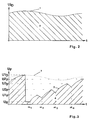
- Fig. 2 shows the breakdown voltage Uj D as a function of time t.
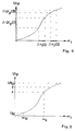
- Fig. 4 and 5 show the maximum values Ui F of the filter voltage of an arbitrary step j as a function of the ignition angle ⁇ i .
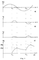
- the functional relationship of the primary voltage U P , the primary current I P , the filter current I F and the filter voltage U F and the time t is shown schematically in FIGS. 1a to d shown.
- the primary voltage U P is to be understood as the voltage that is supplied by the power grid.
- the primary current I P is to be understood as the current which can be drawn from the power grid on the basis of the primary voltage U P.
- the filter current I F is to be understood as the current arising in the electrostatic precipitator used as an electrostatic precipitator.
- the filter current I F is also increased from the ignition angle ⁇ 1 and drops to 0 A at the first zero crossing of the primary voltage U P.
- the filter current I F is adjusted by means of a rectifier, which becomes clear in that the filter current I F is increased again after the ignition angle ⁇ 2, the graph of the function shown running above the abscissa. As a rule, the filter current I F is gradually increased. As shown in Fig.
- the filter voltage U F which arises during operation increases with the ignition angle ⁇ 1 from 0 to the first maximum value U 1 F , which is achieved with half the oscillation period T of the mains frequency. Then the voltage drops until the ignition angle ⁇ 2 is reached. The filter voltage U F is then again increased until after the entire oscillation period T the second maximum value U2 F is reached. The filter voltage U F also increases gradually in accordance with the filter current I F.
- the breakdown voltage Uj D is shown as a function of time t with the hatched area (2) under the breakdown voltage curve (1).
- the breakdown voltage curve (1) corresponds to the fluctuations of the exhaust gas with regard to temperature or concentration of the pollutants.
- FIG. 3 shows the filter voltage U F as a function of time t with the voltage curve (3) for the transition from the first step 1 to the second step 2 of the method for setting the target voltage UZ F with the hatched area (4) below the voltage curve ( 3) is shown schematically, the information 1 for the first step 1 and 2 for the second step 2 being omitted for reasons of clarity.
- the breakdown voltage curve (1) is also shown dotted. If the filter voltage U F reaches the value of the breakdown voltage U1 D , the filter voltage U F suddenly drops to a residual voltage U R. After deionization of the exhaust gas, the voltage is gradually increased according to the voltage curve (3) and the specification of the ignition angle ⁇ 1 to ⁇ 4.
- the target voltage UZ F which is less than the breakdown voltage U1 D , is already reached.
- step j shows the functional relationship between the maximum values Ui F and the ignition angle ⁇ i for any step j of the method for setting the target voltage UZ F shown schematically.
- the differences between two ignition angles ⁇ i (I) and ⁇ i (II), which are the same in magnitude, result in voltage increases ⁇ Ui F (I) and ⁇ Ui F (II), respectively, which result from Amount forth are different.
- the adaptation to the target voltage UZ F must therefore take place more slowly than is necessary in the area of the difference between two firing angles ⁇ i (II), within which the slope of the curve shown is lower.
- step j this can be achieved by replacing the characteristic variable K P of the PI control device in step j with K P , which takes into account the change in the slope with the variable S (j-1).
- the procedure for setting the target voltage UZ F after a breakdown in an electrostatic precipitator is as follows:
- a first step 1 the filter voltage U F 1 is gradually increased by specifying a plurality of ignition angles ⁇ i 1, as shown in FIG. 1 d.
- the difference between two selected ignition angles can be 10 °, for example.
- the respective maximum values U1 F 1, U2 F 1 etc., designated U1 F and U2 F in FIG. 1d, are stored.
- the function Ui F 1 f ( ⁇ i 1) determined for the first step 1. It is advantageous here to connect the maximum values Ui F 1 either by straight lines or to specify a calculated function in the form of a compensation curve, as is shown in FIGS. 4 and 5 is shown. A functional dependency is obtained, which is shown in FIGS.
- FIG. 4 and 5 is shown.
- the filter voltage U F 1 is increased in the first step 1 to the first breakdown voltage U1 D , as is shown in FIG. 3 is shown.
- the filter voltage U F suddenly drops to a residual voltage U R.
- the target voltage UZ F 2 for the second step 2 which is marked in Fig. 3 with UZ F can be given.
- FIG. 5 shows the functional relationship between the maximum values Ui F and the ignition angle ⁇ i for the first step 1, the 1, which characterizes the first step, being omitted for reasons of clarity.
- the ignition angles ⁇ i 2 are specified for the second step 2. This is done in the following way:
- the voltage x which can also be seen in the graph of this function, corresponds to 70 to 85% of the target voltage UZ F 2.
- the voltage x can be assigned an ignition angle ⁇ x .
- the filter voltage U F 2 is increased in a second step by a control until the voltage x is reached, the number of the required ignition angles ⁇ i 2, which is identical to the number of individual stages of the second step 2, being predetermined based on experience, and the Amounts of the individual ignition angles ⁇ i 2 can be selected in the range between ⁇ R and ⁇ x , where ⁇ R is the ignition angle that can be assigned to the residual voltage U R.
- the range between the voltages U R and x is divided according to the selected number of required ignition angles ⁇ i 2 and the associated ignition angles ⁇ i 2 are taken from the graph.
- the difference between the selected ignition angles ⁇ i 2 is generally more than 10 °, so that the hatched area (4) under the voltage curve (3) in the second step 2 according to FIGS. 2 and 3 is larger than in the first step 1 and thus approximates the hatched area (2) under the breakdown voltage curve (1) according to FIG. 2 can be, which results in an improvement in the degree of separation of the electrostatic precipitator. If the voltage x is reached, the filter voltage U F 2 is further increased in a second step 2 by regulation.
- the method for setting the target voltage UZ F is completed after two steps, so that the target voltage UZ F 2 corresponds to the target voltage UZ F.
- the breakdown voltage curve (1) which is shown in FIG. 2 drops during the second step 2, so that the amount of the breakdown voltage U2 D of the second step 2 is less than the voltage y, that of the target voltage UZ F 2 corresponds.
- the target voltage UZ F 2 in the second step 2 since there will be another breakdown prematurely.
- at least one further step must be implemented.
- a corresponding fourth step 4 must be carried out.
- the number of steps is increased until the Target voltage UZ F j can be realized, which then corresponds to the target voltage UZ F.
- the firing angles in the range between ⁇ R and ⁇ x are generally selected at greater intervals than is the case in first step 1 in order to increase the area (4) under the voltage curve (3), which is shown in Fig 3 is to be maximized and the fluctuations in the exhaust gas are largely taken into account.
Landscapes
- Engineering & Computer Science (AREA)
- Automation & Control Theory (AREA)
- Electrostatic Separation (AREA)
Applications Claiming Priority (2)
| Application Number | Priority Date | Filing Date | Title |
|---|---|---|---|
| DE4142501 | 1991-12-21 | ||
| DE4142501A DE4142501C1 (enExample) | 1991-12-21 | 1991-12-21 |
Publications (2)
| Publication Number | Publication Date |
|---|---|
| EP0549007A1 EP0549007A1 (de) | 1993-06-30 |
| EP0549007B1 true EP0549007B1 (de) | 1995-11-08 |
Family
ID=6447832
Family Applications (1)
| Application Number | Title | Priority Date | Filing Date |
|---|---|---|---|
| EP92203453A Expired - Lifetime EP0549007B1 (de) | 1991-12-21 | 1992-11-11 | Verfahren zur Einstellung der Zielspannung UZF nach einem Durchschlag in einem elektrostatischen Abscheider |
Country Status (3)
| Country | Link |
|---|---|
| EP (1) | EP0549007B1 (enExample) |
| AT (1) | ATE129933T1 (enExample) |
| DE (2) | DE4142501C1 (enExample) |
Families Citing this family (1)
| Publication number | Priority date | Publication date | Assignee | Title |
|---|---|---|---|---|
| SE500810E (sv) * | 1993-01-29 | 2003-04-29 | Flaekt Ab | Sätt att vid ¦verslag reglera str¦mtillf¦rseln till en elektrostatisk stoftavskiljare |
Family Cites Families (3)
| Publication number | Priority date | Publication date | Assignee | Title |
|---|---|---|---|---|
| DE3017685A1 (de) * | 1980-05-08 | 1981-11-12 | Metallgesellschaft Ag, 6000 Frankfurt | Verfahren zum regeln der spannung eines in einer anlage eingesetzten elektrofilters |
| DE3910123C1 (en) * | 1989-03-29 | 1990-05-23 | Walther & Cie Ag, 5000 Koeln, De | Method for optimising the energy consumption when operating an electrostatic precipitator |
| DE4111673C1 (enExample) * | 1991-04-10 | 1992-07-02 | Metallgesellschaft Ag, 6000 Frankfurt, De |
-
1991
- 1991-12-21 DE DE4142501A patent/DE4142501C1/de not_active Expired - Lifetime
-
1992
- 1992-11-11 DE DE59204259T patent/DE59204259D1/de not_active Expired - Lifetime
- 1992-11-11 AT AT92203453T patent/ATE129933T1/de not_active IP Right Cessation
- 1992-11-11 EP EP92203453A patent/EP0549007B1/de not_active Expired - Lifetime
Also Published As
| Publication number | Publication date |
|---|---|
| EP0549007A1 (de) | 1993-06-30 |
| DE4142501C1 (enExample) | 1992-12-10 |
| ATE129933T1 (de) | 1995-11-15 |
| DE59204259D1 (de) | 1995-12-14 |
Similar Documents
| Publication | Publication Date | Title |
|---|---|---|
| EP1324831B1 (de) | Verfahren zum betrieb eines elektrofilters | |
| DE4490375C2 (de) | Verfahren zum Steuern der Stromversorgung eines elektrostatischen Abscheiders | |
| EP0031056B1 (de) | Verfahren zum Ermitteln der Filterstromgrenze eines Elektrofilters | |
| DE3327443A1 (de) | Energiesteuerung fuer elektrostatische staubabscheider | |
| EP0030657B1 (de) | Verfahren zum selbsttätigen Führen der Spannung eines Elektrofilters an der Durchschlagsgrenze und Vorrichtung zur Durchführung des Verfahrens | |
| EP0132659A1 (de) | Regeleinrichtung für ein Elektrofilter | |
| DE3249184T1 (de) | Verfahren und einrichtung fuer eine elektrostatische staubausfaellung | |
| EP0549007B1 (de) | Verfahren zur Einstellung der Zielspannung UZF nach einem Durchschlag in einem elektrostatischen Abscheider | |
| DE3048979C2 (de) | Verfahren zum Betrieb eines Elektroabscheiders für die Gasentstaubung und Vorrichtung dazu | |
| EP0038505B1 (de) | Verfahren zum selbsttätigen Führen der Spannung eines Elektro-Filters an der Durchschlagsgrenze | |
| DE3001595A1 (de) | Verfahren zum optimieren der klopfungshaeufigkeit einer elektrofilteranlage | |
| DE2724815C2 (de) | Schaltung zur Steuerung und Stabilisierung der Drehzahl eines Universalmotors | |
| DE69215107T2 (de) | Steuersystem für drossel mit veränderbarer induktivität | |
| DE69109159T2 (de) | Prozessregelungsvorrichtung. | |
| DE3910123C1 (en) | Method for optimising the energy consumption when operating an electrostatic precipitator | |
| DE4220658C1 (enExample) | ||
| DE69330976T2 (de) | Regelungsmethode zur Erreichung eines Sollwertes | |
| DE4140228C2 (de) | Verfahren zur Entstaubung von Rauchgasen | |
| EP0030321B1 (de) | Verfahren und Vorrichtung zum Optimieren einer Elektrofilteranlage | |
| DE1457073A1 (de) | Steuervorrichtung fuer Elektroabscheider | |
| DE3522568A1 (de) | Verfahren zum betrieb eines elektrofilters | |
| DE3001778A1 (de) | Verfahren und einrichtung zur wegregelung eines positionsantriebes | |
| EP0508509B1 (de) | Verfahren zur Bestimmung der optimalen Anzahl von Durchschlägen pro Zeiteinheit Dsn in einem elektrostatischen Abscheider | |
| EP0108928A2 (de) | Verfahren zum Regeln eines Kraftwerkblockes | |
| EP0734774B1 (de) | Verfahren zum Betrieb eines elektrostatischen Abscheiders |
Legal Events
| Date | Code | Title | Description |
|---|---|---|---|
| PUAI | Public reference made under article 153(3) epc to a published international application that has entered the european phase |
Free format text: ORIGINAL CODE: 0009012 |
|
| 17P | Request for examination filed |
Effective date: 19930205 |
|
| AK | Designated contracting states |
Kind code of ref document: A1 Designated state(s): AT CH DE FR GB LI SE |
|
| 17Q | First examination report despatched |
Effective date: 19940902 |
|
| GRAA | (expected) grant |
Free format text: ORIGINAL CODE: 0009210 |
|
| AK | Designated contracting states |
Kind code of ref document: B1 Designated state(s): AT CH DE FR GB LI SE |
|
| REF | Corresponds to: |
Ref document number: 129933 Country of ref document: AT Date of ref document: 19951115 Kind code of ref document: T |
|
| REF | Corresponds to: |
Ref document number: 59204259 Country of ref document: DE Date of ref document: 19951214 |
|
| ET | Fr: translation filed | ||
| GBT | Gb: translation of ep patent filed (gb section 77(6)(a)/1977) |
Effective date: 19960217 |
|
| PLBE | No opposition filed within time limit |
Free format text: ORIGINAL CODE: 0009261 |
|
| 26N | No opposition filed | ||
| PGFP | Annual fee paid to national office [announced via postgrant information from national office to epo] |
Ref country code: GB Payment date: 19971013 Year of fee payment: 6 |
|
| PGFP | Annual fee paid to national office [announced via postgrant information from national office to epo] |
Ref country code: CH Payment date: 19971023 Year of fee payment: 6 Ref country code: AT Payment date: 19971023 Year of fee payment: 6 |
|
| PGFP | Annual fee paid to national office [announced via postgrant information from national office to epo] |
Ref country code: SE Payment date: 19971024 Year of fee payment: 6 |
|
| PGFP | Annual fee paid to national office [announced via postgrant information from national office to epo] |
Ref country code: FR Payment date: 19971113 Year of fee payment: 6 |
|
| PGFP | Annual fee paid to national office [announced via postgrant information from national office to epo] |
Ref country code: DE Payment date: 19971115 Year of fee payment: 6 |
|
| PG25 | Lapsed in a contracting state [announced via postgrant information from national office to epo] |
Ref country code: DE Free format text: LAPSE BECAUSE OF THE APPLICANT RENOUNCES Effective date: 19980423 |
|
| PG25 | Lapsed in a contracting state [announced via postgrant information from national office to epo] |
Ref country code: GB Free format text: LAPSE BECAUSE OF NON-PAYMENT OF DUE FEES Effective date: 19981111 Ref country code: AT Free format text: LAPSE BECAUSE OF NON-PAYMENT OF DUE FEES Effective date: 19981111 |
|
| PG25 | Lapsed in a contracting state [announced via postgrant information from national office to epo] |
Ref country code: SE Free format text: LAPSE BECAUSE OF NON-PAYMENT OF DUE FEES Effective date: 19981112 |
|
| PG25 | Lapsed in a contracting state [announced via postgrant information from national office to epo] |
Ref country code: LI Free format text: LAPSE BECAUSE OF NON-PAYMENT OF DUE FEES Effective date: 19981130 Ref country code: CH Free format text: LAPSE BECAUSE OF NON-PAYMENT OF DUE FEES Effective date: 19981130 |
|
| GBPC | Gb: european patent ceased through non-payment of renewal fee |
Effective date: 19981111 |
|
| REG | Reference to a national code |
Ref country code: CH Ref legal event code: PL |
|
| PG25 | Lapsed in a contracting state [announced via postgrant information from national office to epo] |
Ref country code: FR Free format text: LAPSE BECAUSE OF NON-PAYMENT OF DUE FEES Effective date: 19990730 |
|
| EUG | Se: european patent has lapsed |
Ref document number: 92203453.3 |
|
| REG | Reference to a national code |
Ref country code: FR Ref legal event code: ST |