EP0547377A2 - Stand for X-ray machine - Google Patents
Stand for X-ray machine Download PDFInfo
- Publication number
- EP0547377A2 EP0547377A2 EP92119430A EP92119430A EP0547377A2 EP 0547377 A2 EP0547377 A2 EP 0547377A2 EP 92119430 A EP92119430 A EP 92119430A EP 92119430 A EP92119430 A EP 92119430A EP 0547377 A2 EP0547377 A2 EP 0547377A2
- Authority
- EP
- European Patent Office
- Prior art keywords
- arms
- arm
- fastening device
- ray
- column
- Prior art date
- Legal status (The legal status is an assumption and is not a legal conclusion. Google has not performed a legal analysis and makes no representation as to the accuracy of the status listed.)
- Withdrawn
Links
Images


Classifications
-
- A—HUMAN NECESSITIES
- A61—MEDICAL OR VETERINARY SCIENCE; HYGIENE
- A61B—DIAGNOSIS; SURGERY; IDENTIFICATION
- A61B6/00—Apparatus for radiation diagnosis, e.g. combined with radiation therapy equipment
-
- G—PHYSICS
- G01—MEASURING; TESTING
- G01T—MEASUREMENT OF NUCLEAR OR X-RADIATION
- G01T1/00—Measuring X-radiation, gamma radiation, corpuscular radiation, or cosmic radiation
- G01T1/16—Measuring radiation intensity
- G01T1/161—Applications in the field of nuclear medicine, e.g. in vivo counting
- G01T1/164—Scintigraphy
- G01T1/166—Scintigraphy involving relative movement between detector and subject
Definitions
- the present invention relates to a stand for an X-ray apparatus containing an X-ray tube and an X-ray cassette according to the preamble of patent claim 1.
- a one-piece cross member is fixedly attached to the vertically displaceable and rotatable in a vertical plane fastening device which extends coaxially with one arm on each side of the fastening device.
- the X-ray tube is attached to one arm and the X-ray cassette to the other arm.
- the X-ray tube and the X-ray cassette are arranged on their arms so as to be displaceable in the longitudinal direction of the crossmember, the displacement being able to be done manually or by motor as well as individually or coupled.
- the known tripods have the disadvantage that there must be a free space in the direction of the vertically mounted column in every direction, i.e. both horizontally and vertically, which is due to the total length of the crossmember for the X-ray tube and the X-ray cassette attached to the column is determined.
- This condition makes it difficult to set up the X-ray apparatus when space is limited and, because of the large length of the crossmember, also makes it difficult to handle the positioning conditions in the usual, very different imaging methods.
- the stand according to the invention has the feature stated in the characterizing part of patent claim 1.
- the length of the crossmember is determined by the required distance between the X-ray tube and the X-ray cassette, but not by a longer length of a crossmember taking into account all the adjustment requirements of the X-ray tube and the X-ray cassette, the invention achieves a compact design with a reduced space requirement. Furthermore, since there is no fixed-length cross member, handling the tripod when setting up the desired holder is made considerably easier. In addition, the stand according to the invention allows for further exposures or examinations on the back or front of the patient, in that the X-ray cassette is positioned either under or over a patient couch.
- the two telescopically displaceable arms can be mechanically coupled to one another via a drive device, such that the arms can simultaneously be displaced in opposite directions. This simplifies the adjustment of the x-ray tube and the x-ray cassette with respect to the patient to be examined.
- the drive device can have an assigned drive element for each arm, the transmission ratio between the one drive element and the assigned arm being different from the translation ratio between the other drive element and the assigned arm. It is thereby achieved that the torque of the arm carrying the x-ray tube and of the arm carrying the x-ray cassette in the pivot point located on the column are at least approximately the same size, so that at every set distance between the x-ray tube and the x-ray cassette and in every position of the rotatable cross member there is at least approximately equilibrium with respect to the pivot point.
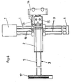
- the present tripod comprises a vertical column 1, a fastening device 2 connected to the column 1 and a cross member 3, generally designated 3, in which two arms 4 and 5 projecting telescopically on both sides of the fastening device are mounted.
- the column 1, the fastening device 2 and the arms 4, 5 essentially consist of box-shaped profile pieces, as will be explained in more detail below with reference to FIG. 5.
- the column 1 is provided at its lower end with a base 6 (FIG. 1) and at its upper end with a drive unit 7 (FIGS. 1, 2).
- the drive unit 7 is used for the controlled movement of two endless chains 8 located in the longitudinal grooves of the column 1.
- the base 6 there is a not shown Deflection device for the chains 8.
- the drive unit 7 is provided with a plate 9 which allows the column 1 shown in FIG. 2 to be fastened in a vertical position to a wall 10.
- the base 6 can also be fastened to the wall 10 in a manner not shown.
- a rotating unit 11 is attached to the two parallel chains 8. 5 carries the fastening device 2 in such a way that the latter can be pivoted relative to the column 1 in a manner known per se by up to 360 ° in a plane parallel to the longitudinal direction of the column 1.
- the two telescopically displaceable arms 4 and 5 are guided parallel to one another vertically at the same height and horizontally next to one another.
- an X-ray tube 14 At the outer end of the arm 4, an X-ray tube 14, a light sighting device 15 and an operating part 16 provided with pushbuttons for the tripod are fastened via a bracket arm 13 which can be swiveled through 360 °.
- an X-ray cassette 17 (also called “bucky”) is attached so that it can be rotated through 360 °.
- FIG. 2 also shows a patient couch 18 under which the x-ray cassette 17 can be positioned.
- the longitudinal extension of the carrier 3 only occupies the required distance of the X-ray tube 14 from the X-ray cassette 17, that is to say that none over the X-ray tube 14 and the X-ray cassette in the longitudinal direction protruding, disturbing sections of the carrier 3 are present.
- the absence of such protruding support sections also allows examinations to be carried out without problems on the top of a patient located on the patient couch 18.
- Each arm 4, 5 can be moved individually and manually in the fastening device 2 by an appropriate distance of the X-ray tube 14 from the X-ray cassette or the X-ray tube 14 and the X-ray cassette 17 from the axis of rotation 29 of the To achieve fastening device 2. This is possible without any effort due to the smooth, but play-free mounting of the arms 4, 5, which will be explained in detail below, in the fastening device without great effort.
- the individual adjustment of the two arm lengths would be relatively time-consuming and would have to be carried out using longitudinal scales, it is advantageous to mechanically couple the longitudinal movements of the two arms 4, 5 with one another.
- a related embodiment is shown schematically in FIGS. 3 and 4.
- the two arms 4 and 5 are each mounted on four pairs of rollers 19 and 20 arranged inside the fastening device 2.
- Two endless chains 21 and 22 are arranged between the two arms 4, 5 and are guided in the end regions of the fastening device 2 via chain wheels 23, 24 and 25, 26, respectively.
- the arm 4 is firmly connected to the chain 21 via a driver 27 and the arm 5 to the chain 22 via a driver 28.
- at least one of the sprocket pairs 23, 24 or 25, 26 arranged on the same axis is designed to be non-rotatable, so that when the one chain is moved, the other chain is also moved.
- the left-hand sprockets 24, 26 are firmly mounted on their shaft and screwed together, while the right-hand sprockets 23, 25 are freely running on their shaft. Since one arm 4 is connected via the driver 27 to the upper run of the associated chain 21, the other arm 5 via the driver 28, on the other hand, to the lower run of the associated chain 22, the coupled movement of the two arms 4, 5 takes place in opposite directions.
- the coupled setting of the two arms 4, 5 can be done purely manually by pushing in or pulling out one of the two arms.
- Another, likewise manual setting option can consist in providing the shaft carrying the pair of chain wheels 23, 25 or 24, 26 on the outside of the fastening device 2 with a rotary wheel or rotary handle.
- a distance locking device 30 which is effective on the chain 21 is provided according to FIG. 4 and is actuated or released, for example, by pressing a button can. Furthermore, it is advantageous to provide the one pair of chain wheels 23, 25 or 24, 26 with a chain tensioner 31 indicated in FIG. 3.
- the column 1 consists of a hollow box section, along which the rotating unit 11 designed as a carriage can be displaced, see also FIGS. 1 and 2.
- the rotating unit 11 has a base plate 34, on which two guide pieces 35 are screwed. Each guide piece 35 contains rollers 36 which run on the shafts 33.
- a ring 37 is also screwed, which is provided with an external toothing 38.
- the base plate 34 carries an outer ring 39 of a tapered bearing
- the inner ring 41 provided with rollers 40 is fixedly attached to a bolt 42 which is pressed into a flange ring 43.
- the flange ring 43 is attached to the rear wall of the fastening device 2, which also has a box-shaped profile.
- the fastening device 2 can therefore be rotated through 360 ° relative to the base plate 34 of the rotary unit 11.
- a locking device 44 is attached to the fastening device 2 according to FIG. 2, which can engage in the external toothing 38 of the ring 37.
- a chain drive is arranged inside the column 1 for driving the rotating unit 11, that is to say for moving it along the column 1 and thus for correspondingly moving the fastening device 2.
- This includes from the two parallel chains 8 which run at the two ends of the column 1 via deflection sprockets 46 indicated in FIG. 5.
- deflection sprockets 46 indicated in FIG. 5.
- the front runs of the two chains 8 are positioned in grooves 49 in the front wall of the column 1 and are thus open to the outside, as is already shown in FIG. 1.
- a driver piece 50 is attached, which has a U-shaped profile.
- the driver piece 50 is connected to the base plate 34 and via an axial deep groove ball bearing 51 to the fastening device 2, 52 being a counter ring.
- a large vertical stroke of the fastening device 2 and thus of the cross member 3 can be achieved with respect to the length of the column 1, for example a vertical stroke of 165 cm with a column length of 185 cm.
- the advantage of the telescopically displaceable arms 4 and 5 can thus be fully exploited.
- rollers 19 and 20 are arranged. From Fig. 5 it can be seen that the box-shaped arms 4 and 5 are provided on their top and bottom with clamping rails 53, into which ground shafts 54 are pressed, which run in the rollers 19 and 20, respectively.
- the rollers 19 and 20 are mounted with central and preferably eccentric bolts 55 in order to be able to adjust the arms 4 and 5 to be free of play. For this purpose, the rollers 19 and 20 can also be adjusted laterally.
- 5 also shows two chain wheels 24, 26 of the total of four chain wheels 23 to 26 of FIGS. 3 and 4 together with the chains 21 and 22 guided through them. 5, the drivers 27 and 28 for the arm 4 and 5 are shown. 3 and 4, the arm 4 carrying the x-ray tube 14 is connected to the chain 21 running over the smaller sprocket 24, while the arm 5 carrying the x-ray cassette is connected to the chain 22 running over the larger sprocket 26 connected is.
- the profile pieces of the column 1, the fastening device 2 and the arms 4, 5 are made of light metal, advantageously of aluminum, there is a very low total weight of the present tripod of, for example, 120 kg without the X-ray tube 14 and the light sighting device 15.
- this can be done Divide the present system into modules, which can be transported separately and, due to the short maximum length of about 2 m, in a normal station wagon or in a passenger lift, and assembled, assembled and connected in a short time at the installation site.
- the operation of the present tripod with X-ray tube and X-ray cassette is very simple, since all tripod functions on the operating part 16 (FIGS. 1, 2) can be operated with one hand.
- the light sighting device 15, with which a central beam is centered on the center of the X-ray cassette 17, the pivoting of the fastening device 2 or the carrier 3 of the arms 4, 5 and the distance locking device 30 are easy to use and can be controlled electronically.
- the present stand can also be used as an auxiliary device for EKG, therapy devices, etc., since it is possible to move the patient couch 18 (FIG. 2) under the end of the arm 5, which normally carries the X-ray cassette 17.
- the cross member 3, the X-ray cassette 17 and the X-ray apparatus 14 can be designed or arranged in mirror symmetry, so that (with reference to FIG. 1) the arm 4 with the X-ray tube 14 to the left of the column 1 and the arm 5 with the X-ray cassette 17 to the right of column 1.
- the column 1 can be moved closer to a wall to the left in a small space, whereas the embodiment according to FIG. 1 (because of the smaller pivoting radius of the arm 4 can be moved closer to a wall on the right).
Abstract
Description
Die vorliegende Erfindung bezieht sich auf ein Stativ für einen eine Röntgenröhre und eine Röntgenkassettte enthaltenden Röntgenapparat gemäss dem Oberbegriff des Patentanspruchs 1.The present invention relates to a stand for an X-ray apparatus containing an X-ray tube and an X-ray cassette according to the preamble of
Bei bekannten, im Handel erhältlichen und in diesbezüglichen Publikationen dargestellten und beschriebenen Stativen ist an der an der Säule vertikal verschiebbaren und in einer Vertikalebene drehbaren Befestigungsvorrichtung ein einteiliger Querträger fest angebracht, welcher sich mit je einem Arm koaxial auf beide Seiten der Befestigungsvorrichtung erstreckt. Auf dem einen Arm wird die Röntgenröhre und auf dem anderen Arm die Röntgenkassette angebracht. Um in der erforderlichen Weise den gegenseitigen Abstand von Röntgenröhre und Röntgenkassette verändern zu können, sind die Röntgenröhre und die Röntgenkassette auf ihren Armen in Längsrichtung des Querträgers verschiebbar angeordnet, wobei die Verschiebung manuell oder motorisch sowie individuell oder gekuppelt erfolgen kann.In known, commercially available tripods shown and described in related publications, a one-piece cross member is fixedly attached to the vertically displaceable and rotatable in a vertical plane fastening device which extends coaxially with one arm on each side of the fastening device. The X-ray tube is attached to one arm and the X-ray cassette to the other arm. In order to be able to change the mutual distance between the X-ray tube and the X-ray cassette in the required manner, the X-ray tube and the X-ray cassette are arranged on their arms so as to be displaceable in the longitudinal direction of the crossmember, the displacement being able to be done manually or by motor as well as individually or coupled.
Die bekannten Stative weisen den Nachteil auf, dass seitlich der vertikal montierten Säule in jeder Richtung, also sowohl horizontal als auch vertikal, im Behandlungszimmer ein freier Raum vorhanden sein muss, welcher durch die Gesamtlänge des an der Säule angebrachten Querträgers für die Röntgenröhre und die Röntgenkassette bestimmt ist. Diese Bedingung erschwert das Einrichten des Röntgenapparats bei gedrängten Platzverhältnissen und erschwert zudem wegen der grossen Länge des Querträgersdessen Handhabung für die Positionierbedingungen bei den üblichen, stark unterschiedlichen Aufnahmeverfahren.The known tripods have the disadvantage that there must be a free space in the direction of the vertically mounted column in every direction, i.e. both horizontally and vertically, which is due to the total length of the crossmember for the X-ray tube and the X-ray cassette attached to the column is determined. This condition makes it difficult to set up the X-ray apparatus when space is limited and, because of the large length of the crossmember, also makes it difficult to handle the positioning conditions in the usual, very different imaging methods.
Es ist Aufgabe der vorliegenden Erfindung, ein Stativ der eingangs genannten Art zu schaffen, dessen Platzbedarf in jeder Richtung verhältnismässig gering und dessen Handhabung erleichtert ist.It is an object of the present invention to provide a tripod of the type mentioned, the space requirement in each direction is relatively small and the handling is easier.
Zur Lösung dieser Aufgabe weist das erfindungsgemässe Stativ das im kennzeichnenden Teil des Patentanspruchs 1 angeführten Merkmal auf.To achieve this object, the stand according to the invention has the feature stated in the characterizing part of
Da beim erfindungsgemässen Stativ die Länge des Querträgers durch den erforderlichen Abstand zwischen der Röntgenröhre und der Röntgenkassette bestimmt ist, nicht aber durch eine grössere Länge eines alle Einstellerfordernisse von Röntgenröhre und Röntgenkassette berücksichtigenden Querträgers, wird durch die Erfindung eine kompakte Bauweise mit verringertem Platzbedarf erzielt. Da ferner kein Querträger fester Länge vorliegt, ist die Handhabung des Stativs beim Einrichten bezüglich der gewünschten Aufnahme wesentlich erleichtert. Zudem erlaubt das erfindungsgemässe Stativ ohne weiteres Aufnahmen bzw. Untersuchungen auf der Hinter- oder Vorderseite des Patienten, indem die Röntgenkassette entweder unter bzw. über einer Patientenliege positioniert wird.Since in the stand according to the invention the length of the crossmember is determined by the required distance between the X-ray tube and the X-ray cassette, but not by a longer length of a crossmember taking into account all the adjustment requirements of the X-ray tube and the X-ray cassette, the invention achieves a compact design with a reduced space requirement. Furthermore, since there is no fixed-length cross member, handling the tripod when setting up the desired holder is made considerably easier. In addition, the stand according to the invention allows for further exposures or examinations on the back or front of the patient, in that the X-ray cassette is positioned either under or over a patient couch.
Gemäss Patentanspruch 2 können die beiden teleskopisch verschiebbaren Arme über eine Antriebsvorrichtung mechanisch miteinander gekuppelt sein, derart, dass die Arme gleichzeitig in entgegengesetzten Richtungen verschiebbar sind. Dadurch wird die Einstellung der Röntgenröhre und der Röntgenkassette bezüglich des zu untersuchenden Patienten erleichtert.According to
Die Antriebsvorrichtung kann hierbei für jeden Arm ein zugeordnetes Antriebselement aufweisen, wobei das Uebersetzungsverhältnis zwischen dem einen Antriebselement und dem zugeordneten Arm verschieden vom Uebersetzungsverhältnis zwischen dem anderen Antriebselement und dem zugeordneten Arm ist. Dadurch wird erreicht, dass die Drehmoment des die Röntgenröhre tragenden Arms und des die Röntgenkassette tragenden Arms im an der Säule befindlichen Drehpunkt mindestens angenähert entgegengesetzt gleich gross sind, so dass bei jeder eingestellten Distanz zwischen der Röntgenröhre und der Röntgenkassette und bei jeder Lage des drehbaren Querträgers mindestens angenähert Gleichgewicht bezüglich des Drehpunkts vorliegt.The drive device can have an assigned drive element for each arm, the transmission ratio between the one drive element and the assigned arm being different from the translation ratio between the other drive element and the assigned arm. It is thereby achieved that the torque of the arm carrying the x-ray tube and of the arm carrying the x-ray cassette in the pivot point located on the column are at least approximately the same size, so that at every set distance between the x-ray tube and the x-ray cassette and in every position of the rotatable cross member there is at least approximately equilibrium with respect to the pivot point.
Weitere vorteilhafte Ausführungsformen des Erfindungsgegenstandes sind in den nachfolgenden Patentansprüchen definiert.Further advantageous embodiments of the subject matter of the invention are defined in the following patent claims.
Ausführungsbeispiele des erfindungsgemässen Stativs werden nachstehend anhand der Zeichnungen erläutert. Es zeigen:
- Fig 1 und 2 eine Vorder- und eine Seitenansicht des Stativs mit Röntgenröhre und Röntgenkassette bei horizontal eingestelltem Querträger;
- Fig. 3 und 4 eine Vorder- und eine Draufsicht der die Arme des Querträgers führenden Befestigungsvorrichtung mit angedeuteten Antriebselementen für die teilweise dargestellten Arme;
- Fig. 5 einen Horizontalschnitt durch die Drehachse der an der Säule mit vertikaler Lage des Querträgers gemäss Fig. 2 angebrachten Befestigungsvorrichtung und
- Fig. 6 eine Vorderansicht wie Fig. 1 eines zweiten Ausführungsbeispiels und
- Fig. 7 und 8 eine Vorder- und eine Draufsicht des Querträgers wie in Fig. 3, wobei Teile weggebrochen bzw. weggelassen sind.
- 1 and 2 show a front and a side view of the stand with an X-ray tube and an X-ray cassette with the cross member set horizontally;
- Figures 3 and 4 are a front and a plan view of the fastening device guiding the arms of the cross member with indicated drive elements for the partially shown arms;
- Fig. 5 is a horizontal section through the axis of rotation of the attached to the column with the vertical position of the cross member according to FIG. 2 and
- Fig. 6 is a front view like Fig. 1 of a second embodiment and
- 7 and 8 are a front and a plan view of the cross member as in Fig. 3, with parts broken away or omitted.
Gemäss Fig. 1 und 2 umfasst das vorliegende Stativ eine vertikale Säule 1, eine mit der Säule 1 verbundene Befestigungsvorrichtung 2 und einen allgemein mit 3 bezeichneten Querträger 3, in welchem zwei beidseitig der Befestigungsvorrichtung 2 herausragende, teleskopartig verschiebbare Arme 4 und 5 gelagert sind. Wie ersichtlich bestehen die Säule 1, die Befestigungsvorrichtung 2 und die Arme 4, 5 im wesentlichen aus kastenförmigen Profilstücken, wie dies nachstehend anhand der Fig. 5 noch näher erläutert wird.1 and 2, the present tripod comprises a
Die Säule 1 ist an ihrem unteren Ende mit einem Sockel 6 (Fig. 1) und an ihrem oberen Ende mit einer Antriebseinheit 7 (Fig. 1, 2) versehen. Die Antriebseinheit 7 dient der gesteuerten Bewegung zweier in Längsnuten der Säule 1 befindlichen endlosen Ketten 8. Im Sockel 6 befindet sich eine nicht näher dargestellte Umlenkvorrichtung für die Ketten 8. Die Antriebseinheit 7 ist mit einer Platte 9 versehen, welche die in Fig. 2 dargestellte Befestigung der Säule 1 in vertikaler Position an einer Wand 10 erlaubt. Auch der Sockel 6 kann in nicht dargestellter Weise an der Wand 10 befestigt sein.The
An den beiden parallelen Ketten 8 ist eine Dreheinheit 11 befestigt. Diese trägt über einen nachfolgend anhand von Fig. 5 noch näher beschriebenen Drehmechanismus 12 die Befestigungsvorrichtung 2 derart, dass die letztere gegenüber der Säule 1 in an sich bekannter Weise um bis zu 360° in einer zur Längsrichtung der Säule 1 parallelen Ebene schwenkbar ist.A rotating
In der Befestigungsvorrichtung 2 sind die beiden teleskopartig verschiebbaren Arme 4 und 5 vertikal in gleicher Höhe und horizontal nebeneinander parallel zueinander geführt. Am äusseren Ende des Arms 4 sind über einen um 360° schwengbaren Bügelarm 13 eine Röntgenröhre 14, eine Lichtvisiervorrichtung 15 und ein mit Drucktasten versehener Bedienungsteil 16 für das Stativ befestigt. Am äusseren Ende des anderen Arms 5 ist eine Röntgenkassette 17 (auch "Bucky" genannt) um 360° drehbar angebracht. In Fig. 2 ist zudem eine Patientenliege 18 dargestellt, unter welcher die Röntgenkassette 17 positioniert werden kann. Es ist ersichtlich, dass zufolge der teleskopartigen Lagerung der beiden Arme 4 und 5 in der Befestigungsvorrichtung 2 die Längs- ausdehnung des Trägers 3 jeweils nur den benötigten Abstand der Röntgenröhre 14 von der Röntgenkassette 17 beansprucht, das heisst, dass keine über die Röntgenröhre 14 und die Röntgenkassette in Längsrichtung vorstehenden, störenden Abschnitte des Trägers 3 vorhanden sind. Das Fehlen solcher vorstehender Trägerabschnitte erlaubt es auch, problemlos Untersuchungen auf der Oberseite eines auf der Patientenliege 18 befindlichen Patienten vorzunehmen.In the
Jeder Arm 4, 5 kann an sich individuell und manuell in der Befestigungsvorrichtung 2 verschoben werden, um einen zweckmässigen Abstand der Röntgenröhre 14 von der Röntgenkassette bzw. der Röntgenröhre 14 und der Röntgenkassette 17 von der Drehachse 29 der Befestigungsvorrichtung 2 zu erzielen. Dies ist ohne Kraftaufwand wegen der nachstehend noch im einzelnen erläuterten, leichtgängigen, aber spielfreien Lagerung der Arme 4, 5 in der Befestigungsvorrichtung ohne grossen Kraftaufwand möglich. Da jedoch die individuelle Einstellung der beiden Armlängen verhältnismässig zeitraubend wäre und anhand von Längsskalen vorgenommen werden müsste, ist es von Vorteil, die Längsbewegungen der beiden Arme 4, 5 miteinander mechanisch zu kuppeln. Ein diesbezügliches Ausführungsbeispiel ist in den Fig. 3 und 4 schematisch dargestellt.Each
Wie ersichtlich, sind die beiden Arme 4 und 5 im Innern der Befestigungsvorrichtung 2 je auf vier paarweise angeordneten Rollen 19 bzw. 20 gelagert. Zwischen den beiden Armen 4, 5 sind zwei endlose Ketten 21 bzw. 22 angeordnet, die in den Endbereichen der Befestigungsvorrichtung 2 über Kettenräder 23, 24 bzw. 25, 26 geführt sind. Der Arm 4 ist mit der Kette 21 über einen Mitnehmer 27 und der Arm 5 mit der Kette 22 über einen Mitnehmer 28 fest verbunden. Ferner ist mindestens eines der auf der gleichen Achse angeordneten Kettenrad-Paare 23, 24 bzw. 25, 26 drehfest ausgebildet, so dass bei der Bewegung der einen Kette auch die andere Kette mitbewegt wird. Beispielsweise sind die linksseitigen Kettenräder 24, 26 fest auf ihrer Welle montiert und miteinander verschraubt, während die rechtsseitigen Kettenräder 23, 25 frei laufend auf ihrer Welle gelagert sind. Da der eine Arm 4 über den Mitnehmer 27 mit dem oberen Trum der zugeordneten Kette 21 verbunden ist, der andere Arm 5 über den Mitnehmer 28 dagegen mit dem unteren Trum der zugeordneten Kette 22, erfolgt die gekuppelte Bewegung der beiden Arme 4, 5 gegenläufig.As can be seen, the two
Aus Fig. 3 ist ferner ersichtlich, dass die Kettenräder 23, 24 des Antriebs des Armes 4 einen kleineren Durchmesser als die Kettenräder 25, 26 des Armes 5 haben. Dies hat zur Folge, dass bei einer Drehbewegung der Kettenräder der Arm 4, welcher die Röntgenröhre 14 trägt, langsamer läuft als der die Röntgenkassette 17 tragende Arm 5. Dadurch kann erreicht werden, dass sich die an der Drehachse 29 (Fig. 4) wirksamen, durch die Röntgenröhre 14 und gegensinnig durch die Röntgenkassette 17 ausgeübten Drehmomente kompensieren, also ein Gleichgewicht zwischen Röntgenröhre 14 und Röntgenkassette 17 besteht, und zwar für jede Distanz zwischen diesen beiden und für jede Schräglage des Querträgers 3. Falls das angestrebte Gleichgewicht nach der Montage der Röntgenröhre 14 und der Röntgenkassette 17 nicht vorhanden ist, kann der Gleichgewichtszustand durch einmaliges Verschieben der Röntgenröhre 14 oder der Röntgenkassette auf den sie tragen Armen 4 bzw. 5 leicht erzielt werden.From Fig. 3 it can also be seen that the
Die gekuppelte Einstellung der beiden Arme 4, 5 kann rein manuell durch Einschieben bzw. Ausziehen eines der beiden Arme erfolgen. Eine andere, ebenfalls manuelle Einstellmöglichkeit kann darin bestehen, die das Kettenradpaar 23, 25 oder 24, 26 tragende Welle auf der Aussenseite der Befestigungsvorrichtung 2 mit einem Drehrad oder Drehgriff zu versehen. Schliesslich ist es auch möglich, einen motorischen Antrieb für die genannten Kettenräder vorzusehen und über eine der Drucktasten des Bedienungsteils 16 (Fig. 1, 2) zu steuern.The coupled setting of the two
Um zu verhindern, dass sich die eingestellte Lage der leichtgängigen Arme 4, 5 bei einer Schräglage des Querträgers 3 verschiebt, ist gemäss Fig. 4 eine auf die eine Kette 21 wirksame Distanz-Arretiervorrichtung 30 vorgesehen, die beispielsweise durch Knopfdruck betätigt bzw. gelöst werden kann. Ferner ist es vorteilhaft, das eine Paar der Kettenräder 23, 25 bzw. 24, 26 mit einem in Fig. 3 angedeuteten Kettenspanner 31 zu versehen.In order to prevent the set position of the smooth-running
Anhand der Fig. 5 wird im folgenden ein beispielsweiser Aufbau der Vertikal-Positionierung und der Drehpositionierung des Trägers 3 sowie der teilweise bereits anhand der Fig. 3 und 4 erläuterten Verschiebung der beiden Arme 4 und 5 des Trägers 3 beschrieben.5, an example of the structure of the vertical positioning and the rotational positioning of the
Die Säule 1 besteht aus einem Hohlkasten-Profilstück, längs welchem die als Wagen ausgebildete Dreheinheit 11 verschiebbar ist, vergleiche auch Fig. 1 und 2. Als Führung für die Dreheinheit 11 sind an den beiden Schmalseiten der Säule 1 je eine Wellenklemmschiene 32 angebracht, in welche eine geschliffene Welle 33 eingepresst ist. Die Dreheinheit 11 hat eine Grundplatte 34, an welcher zwei Führungsstücke 35 angeschraubt sind. Jedes Führungsstück 35 enthält Rollen 36, die auf den Wellen 33 laufen. Auf der Vorderseite der Grundplatte 34 ist zudem ein Ring 37 aufgeschraubt,der mit einer Aussenverzahnung 38 versehen ist. Ferner trägt die Grundplatte 34 einen Aussenring 39 eines Kegellagers, dessen mit Rollen 40 versehener Innenring 41 auf einem Bolzen 42 fest angebracht ist, welcher in einen Flanschring 43 eingepresst ist. Der Flanschring 43 ist an der Rückwand der Befestigungsvorrichtung 2 angebracht, welche ebenfalls ein kastenförmiges Profil hat. Die Befestigungsvorrichtung 2 ist demnach gegenüber der Grundplatte 34 der Dreheinheit 11 um 360° drehbar. Um die Befestigungseinheit 2 in einer gewählten Drehlage festzuhalten, ist an der Befestigungsvorrichtung 2 gemäss Fig. 2 eine Arretiervorrichtung 44 angebracht, die in die Aussenverzahnung 38 des Rings 37 eingreifen kann.The
Für den Antrieb der Dreheinheit 11, das heisst zu ihrer Verschiebung längs der Säule 1 und damit zur entsprechenden Verschiebung der Befestigungsvorrichtung 2 ist im Innern der Säule 1 ein Kettenantrieb angeordnet. Dieser besteht u.a. aus den zwei parallelgeführten endlosen Ketten 8 , welche an den beiden Enden der Säule 1 über in Fig. 5 angedeutete Umlenk-Kettenräder 46 laufen. Auf der Welle 47 der oberen Umlenk-Kettenräder 46 sind zudem zwei weitere Kettenräder 48 angebracht, welche durch einen am oberen Ende der Säule 1 in der Antriebseinheit 7 (Fig. 1, 2) befindlichen Elektromotor angetrieben werden.A chain drive is arranged inside the
Die vorderen Trums der beiden Ketten 8 sind in Nuten 49 der Frontwand der Säule 1 positioniert und damit gegen aussen offen, wie dies bereits in Fig. 1 dargestellt ist. An den Ketten 8 ist ein Mitnehmerstück 50 befestigt, das ein U-förmiges Profil hat. Das Mitnehmerstück 50 ist mit der Grundplatte 34 und über ein Axial-Rillenkugellager 51 mit der Befestigungsvorrichtung 2 verbunden, wobei mit 52 ein Konterring bezeichnet ist.The front runs of the two
Durch die Anwendung des beschriebenen Kettenantriebs lässt sich bezüglich der Länge der Säule 1 ein grosser Vertikalhub der Befestigungsvorrichtung 2 und damit des Querträgers 3 erzielen, beispielsweise ein Vertikalhub von 165 cm bei einer Säulenlänge von 185 cm. Damit kann der Vorteil der teleskopartig verschiebbaren Arme 4 und 5 voll ausgenutzt werden.By using the chain drive described, a large vertical stroke of the
Zur Lagerung und Führung der beiden Arme 4 und 5 sind, wie anhand der Fig. 3 und 4 bereits angeführt, die Rollen 19 und 20 angeordnet. Aus Fig. 5 ist ersichtlich, dass die kastenförmigen Arme 4 und 5 an ihrer Ober- und Unterseite mit Klemmschienen 53 versehen sind, in welche geschliffene Wellen 54 eingepresst sind, die in den Rollen 19 bzw. 20 laufen. Die Rollen 19 und 20 sind mit zentrischen und vorzugsweise exzentrischen Bolzen 55 montiert, um eine spielfreie Lagerung der Arme 4 und 5 einstellen zu können. Die Rollen 19 und 20 können hierzu auch seitlich eingestellt werden.For the storage and guidance of the two
In Fig. 5 sind auch zwei Kettenräder 24, 26 der insgesamt vier Kettenräder 23 bis 26 der Fig. 3 und 4 samt den durch sie geführten Ketten 21 und 22 dargestellt. Ferner sind aus Fig. 5 die Mitnehmer 27 und 28 für den Arm 4 bzw. 5 dargestellt. Hierbei ist, wie bereits anhand der Fig. 3 und 4 erwähnt, der die Röntgenröhre 14 tragende Arm 4 mit der über das kleinere Kettenrad 24 laufenden Kette 21 verbunden, während der die Röntgenkassette tragende Arm 5 mit der über das grössere Kettenrad 26 laufenden Kette 22 verbunden ist.5 also shows two
Da die Profilstücke der Säule 1, der Befestigungsvorrichtung 2 und der Arme 4, 5 aus Leichtmetall mit Vorteil aus Aluminium bestehen, ergibt sich ein sehr niedriges Gesamtgewicht des vorliegenden Stativs von beispielsweise 120 kg ohne die Röntgenröhre 14 und die Lichtvisiervorrichtung 15. Zudem lässt sich das vorliegende System modulweise in Baueinheiten aufteilen, die getrennt und zufolge der geringen Maximallänge von etwa 2 m in einem gewöhnlichen Kombiwagen bzw. in einem Personenlift transportiert und innert kurzer Zeit am Aufstellungsort zusammengesetzt, fertig montiert und angeschlossen werden können.Since the profile pieces of the
Die Bedienung des vorliegenden Stativs mit Röntgenröhre und Röntgenkassette ist sehr einfach, da alle Stativfunktionen am Bedienungsteil 16 (Fig. 1, 2) mit einer Hand bedient werden können. Die Lichtvisiervorrichtung 15, mit welcher ein Zentralstrahl auf den Mittelpunkt der Röntgenkassette 17 zentriert wird, ferner die Schwenkung der Befestigungsvorrichtung 2 bzw. des Trägers 3 der Arme 4, 5 und die Distanz-Arretiervorrichtung 30 sind einfach zu bedienen und können elektronisch gesteuert sein.The operation of the present tripod with X-ray tube and X-ray cassette is very simple, since all tripod functions on the operating part 16 (FIGS. 1, 2) can be operated with one hand. The
Zu erwähnen ist noch, dass das vorliegende Stativ auch als Hilfsgerät für EKG, Therapiegeräte usw. verwendet werden kann, da es möglich ist, die Patientenliege 18 (Fig. 2) unter das Ende des normalerweise die Röntgenkassette 17 tragenden Arms 5 zu fahren.It should also be mentioned that the present stand can also be used as an auxiliary device for EKG, therapy devices, etc., since it is possible to move the patient couch 18 (FIG. 2) under the end of the
Beim beschriebenen Beispiel können der Querträger 3, die Röntgenkassette 17 und der Röntgenapparat 14 spiegelsymmetrisch ausgebildet bzw. angeordnet sein, so dass sich (bezogen auf Fig. 1) der Arm 4 mit der Röntgenröhre 14 links der Säule 1 und der Arm 5 mit der Röntgenkassette 17 rechts von der Säule 1 befinden. Damit kann die Säule 1 in einem kleinen Raum nach links näher gegen eine Wand gerückt werden, wogegen die Ausführungsform nach Fig. 1 (wegen des kleineren Schwenkradius des Armes 4 näher zu einer rechts stehenden Wand rückbar ist.In the example described, the
Bei noch engeren Platzverhältnissen kann, wie das Beispiel nach den Fig. 6 bis 8 zeigt, nur der die Röntgenkassette 17 tragende Arm 5 des Querträgers 3 längenverstellbar ausgebildet sein, wogegen die Röntgenröhre 14 mittels eines Adapters 56 an der Befestigungsvorrichtung 2 mit vorgegebenem Radialabstand zur Drehachse 29 angeordnet ist. Diese Ausführungsform hat zwar den Nachteil. dass nur bei einem bestimmten Auszug des Armes 5 ein Gleichgewichtszustand besteht in dem der Querträger 3 mühelos gedreht werden kann. Mit einer geeigneten Sicherheitsschaltung kann diese Gleichgewichtsauszugslage aber von einer Bedienungsperson problemlos eingestellt werden. Die Vorteile demgegenüber sind, dass in der Raumlänge - ohne Einschränkung für den Röntgenbetrieb - 50 bis 60 cm eingespart werden können, wobei auch der Raumbedarf für die Vertikalstellung kleiner wird.6 to 8, only the
Claims (20)
Applications Claiming Priority (2)
| Application Number | Priority Date | Filing Date | Title |
|---|---|---|---|
| CH3394/91 | 1991-11-20 | ||
| CH339491A CH684737A5 (en) | 1991-11-20 | 1991-11-20 | Tripod for a fluoroscope. |
Publications (2)
| Publication Number | Publication Date |
|---|---|
| EP0547377A2 true EP0547377A2 (en) | 1993-06-23 |
| EP0547377A3 EP0547377A3 (en) | 1993-08-04 |
Family
ID=4255031
Family Applications (1)
| Application Number | Title | Priority Date | Filing Date |
|---|---|---|---|
| EP19920119430 Withdrawn EP0547377A3 (en) | 1991-11-20 | 1992-11-13 | Stand for x-ray machine |
Country Status (2)
| Country | Link |
|---|---|
| EP (1) | EP0547377A3 (en) |
| CH (1) | CH684737A5 (en) |
Cited By (3)
| Publication number | Priority date | Publication date | Assignee | Title |
|---|---|---|---|---|
| ES2152794A1 (en) * | 1997-12-05 | 2001-02-01 | Suinsa Subcontratas Internacio | Support pillar and platform for radiological scanning unit |
| US7543988B2 (en) | 2005-12-01 | 2009-06-09 | Siemens Aktiengesellschaft | X-ray device for imaging at least one part of an examination object |
| US7899155B2 (en) | 2005-10-14 | 2011-03-01 | Siemens Aktiengessellschaft | Stand for holding a radiation detector for a radiation therapy device |
Citations (5)
| Publication number | Priority date | Publication date | Assignee | Title |
|---|---|---|---|---|
| US3254223A (en) * | 1962-10-15 | 1966-05-31 | Westinghouse Electric Corp | Vertical radiographic unit |
| DE1541126A1 (en) * | 1965-09-21 | 1969-09-04 | Generay Gen Radiologica | Tiltable table for X-ray examinations |
| US3838286A (en) * | 1973-11-16 | 1974-09-24 | Gen Electric | X-ray table with self-storing tomographic coupling bar |
| EP0036495A1 (en) * | 1980-03-19 | 1981-09-30 | Mediprix AG | X-ray diagnostic apparatus |
| FR2653005A1 (en) * | 1989-10-12 | 1991-04-19 | Gen Electric Cgr | Device for activating and manoeuvring an examination arm of an X-ray apparatus, and apparatus comprising this device |
-
1991
- 1991-11-20 CH CH339491A patent/CH684737A5/en not_active IP Right Cessation
-
1992
- 1992-11-13 EP EP19920119430 patent/EP0547377A3/en not_active Withdrawn
Patent Citations (5)
| Publication number | Priority date | Publication date | Assignee | Title |
|---|---|---|---|---|
| US3254223A (en) * | 1962-10-15 | 1966-05-31 | Westinghouse Electric Corp | Vertical radiographic unit |
| DE1541126A1 (en) * | 1965-09-21 | 1969-09-04 | Generay Gen Radiologica | Tiltable table for X-ray examinations |
| US3838286A (en) * | 1973-11-16 | 1974-09-24 | Gen Electric | X-ray table with self-storing tomographic coupling bar |
| EP0036495A1 (en) * | 1980-03-19 | 1981-09-30 | Mediprix AG | X-ray diagnostic apparatus |
| FR2653005A1 (en) * | 1989-10-12 | 1991-04-19 | Gen Electric Cgr | Device for activating and manoeuvring an examination arm of an X-ray apparatus, and apparatus comprising this device |
Cited By (4)
| Publication number | Priority date | Publication date | Assignee | Title |
|---|---|---|---|---|
| ES2152794A1 (en) * | 1997-12-05 | 2001-02-01 | Suinsa Subcontratas Internacio | Support pillar and platform for radiological scanning unit |
| US7899155B2 (en) | 2005-10-14 | 2011-03-01 | Siemens Aktiengessellschaft | Stand for holding a radiation detector for a radiation therapy device |
| DE102005049684B4 (en) * | 2005-10-14 | 2016-06-16 | Siemens Healthcare Gmbh | Stand for mounting a radiation detector for a radiotherapy device and a radiotherapy device with a tripod for holding a radiation detector |
| US7543988B2 (en) | 2005-12-01 | 2009-06-09 | Siemens Aktiengesellschaft | X-ray device for imaging at least one part of an examination object |
Also Published As
| Publication number | Publication date |
|---|---|
| EP0547377A3 (en) | 1993-08-04 |
| CH684737A5 (en) | 1994-12-15 |
Similar Documents
| Publication | Publication Date | Title |
|---|---|---|
| DE3532605C2 (en) | Medical diagnostic facility | |
| DE3217478C2 (en) | ||
| EP0670123B1 (en) | Height adjustable work table | |
| EP0832603B1 (en) | Examination table | |
| EP0160869B1 (en) | Data display terminal support | |
| DE10196489B3 (en) | Operating table, in particular for surgical interventions | |
| EP0074019A2 (en) | Control desk | |
| DE1474238B2 (en) | DEVICE FOR SUPPORTING A HEAVY ROLLER ABOVE THE GROUND | |
| DE1025563B (en) | Patient stretcher for X-ray diagnostics | |
| EP0290749A2 (en) | Carriage for travelling along an enrobed cable | |
| EP0364822A2 (en) | Table with a frame and a top as well as an adjusting device for varying the height and the inclination of the top of the table | |
| EP0199079A1 (en) | Device for adjusting the height of a support for a medical apparatus on a vertical stand | |
| EP0565833A1 (en) | Device for perpendicularly aligning the upright axis of a superstructure turnably and inclinably mounted on an understructure | |
| EP0547377A2 (en) | Stand for X-ray machine | |
| DE19647544C1 (en) | Servo drive for furniture, e.g. to adjust hospital bed | |
| EP0528072B1 (en) | Lifting platform | |
| EP0490107A1 (en) | Examination table for patients | |
| DE3933237C2 (en) | ||
| EP0788767A1 (en) | X-ray diagnostic apparatus | |
| DE3540666C2 (en) | Device for the vertical alignment of the vertical axis of a structure connected to a base frame so that it can be rotated and tilted | |
| DE2361566C3 (en) | Drilling device | |
| DE3609724C1 (en) | Supporting and drive device for a detector head | |
| DE968128C (en) | Device for examination with X-rays | |
| DE951661C (en) | Electromedical device | |
| EP3572056B1 (en) | Stretcher support device |
Legal Events
| Date | Code | Title | Description |
|---|---|---|---|
| PUAI | Public reference made under article 153(3) epc to a published international application that has entered the european phase |
Free format text: ORIGINAL CODE: 0009012 |
|
| PUAL | Search report despatched |
Free format text: ORIGINAL CODE: 0009013 |
|
| AK | Designated contracting states |
Kind code of ref document: A2 Designated state(s): AT BE CH DE DK ES FR GB IT LI NL PT SE |
|
| AK | Designated contracting states |
Kind code of ref document: A3 Designated state(s): AT BE CH DE DK ES FR GB IT LI NL PT SE |
|
| 17P | Request for examination filed |
Effective date: 19940119 |
|
| 17Q | First examination report despatched |
Effective date: 19950704 |
|
| STAA | Information on the status of an ep patent application or granted ep patent |
Free format text: STATUS: THE APPLICATION IS DEEMED TO BE WITHDRAWN |
|
| 18D | Application deemed to be withdrawn |
Effective date: 19951115 |