EP0546664A1 - Cylindre fermé de remplissage pour coulée sous pression - Google Patents
Cylindre fermé de remplissage pour coulée sous pression Download PDFInfo
- Publication number
- EP0546664A1 EP0546664A1 EP92309573A EP92309573A EP0546664A1 EP 0546664 A1 EP0546664 A1 EP 0546664A1 EP 92309573 A EP92309573 A EP 92309573A EP 92309573 A EP92309573 A EP 92309573A EP 0546664 A1 EP0546664 A1 EP 0546664A1
- Authority
- EP
- European Patent Office
- Prior art keywords
- shot sleeve
- internal bore
- filling
- shot
- filling cylinder
- Prior art date
- Legal status (The legal status is an assumption and is not a legal conclusion. Google has not performed a legal analysis and makes no representation as to the accuracy of the status listed.)
- Granted
Links
Images


Classifications
-
- B—PERFORMING OPERATIONS; TRANSPORTING
- B22—CASTING; POWDER METALLURGY
- B22D—CASTING OF METALS; CASTING OF OTHER SUBSTANCES BY THE SAME PROCESSES OR DEVICES
- B22D17/00—Pressure die casting or injection die casting, i.e. casting in which the metal is forced into a mould under high pressure
- B22D17/20—Accessories: Details
- B22D17/2015—Means for forcing the molten metal into the die
- B22D17/2053—Means for forcing the molten metal into the die using two or more cooperating injection pistons
-
- B—PERFORMING OPERATIONS; TRANSPORTING
- B22—CASTING; POWDER METALLURGY
- B22D—CASTING OF METALS; CASTING OF OTHER SUBSTANCES BY THE SAME PROCESSES OR DEVICES
- B22D17/00—Pressure die casting or injection die casting, i.e. casting in which the metal is forced into a mould under high pressure
- B22D17/20—Accessories: Details
- B22D17/30—Accessories for supplying molten metal, e.g. in rations
Definitions
- the present invention relates to a method and apparatus for die casting molten material, and more particularly, to a method and apparatus for injecting a shot of molten material into the cavity of a die.
- Die casting is frequently used as a method for forming articles from molten material.
- the present invention will be described in terms of casting molten metal; however, it should be understood the invention may be practised with other materials which may be cast from an initially liquid state.
- two or more die parts are provided such that, when brought together, they form a cavity which defines the shape of the article to be cast.
- Molten metal is introduced into the cavity and allowed to cool. If desired, the metal may be squeeze cast under high pressure to yield a heat treatable or weldable casting.
- the die parts are opened and the cast article is removed.
- molten metal has been introduced into a die by means of a shot sleeve.
- Fig. 1 shows a horizontal die casting apparatus with a shot sleeve arrangement according to the prior art.
- the die 10 includes an ejector die 12 mounted to a movable platen 14 and a cover die 16 mounted to a stationary platen 18. Together, the dies 12 and 16 form a cavity 19 into which a shot of molten metal will be introduced.
- a cylindrical shot sleeve 20 is disposed passing axially through the stationary platen 18 and the cover die 16 in fluid communication with the cavity 19.
- the upper surface of the outer wall near the end of the shot sleeve 20 is penetrated by an open pouring or filling hole 22. Molten metal 24 is ladled through the filling hole 22 into the interior of the shot sleeve 20.
- a plunger 26 seals off the outer end of the shot cylinder and reciprocates within the shot cylinder 20 to inject the molten metal into the die.
- the plunger 26 is connected axially to a plunger rod 28, crosshead adapter 30, and shot cylinder 32.
- the shot cylinder 32 is typically an hydraulic cylinder having a reciprocating shot cylinder rod 34 which causes the plunger 26 to advance toward the die 10 and withdraw therefrom.
- the outer end of the shot cylinder rod has threads 36 to allow for adjustment of the shot size and stroke length.
- the diameter of the sleeve 20 must be enlarged to provide an air space as well as for the necessary volume of molten metal. This enlargement of the shot sleeve diameter reduces the mechanical advantage of the shot cylinder 32, making the apparatus less suitable for squeeze casting.
- Fig. 2 shows the effect of the injection stroke of the plunger 26 on the molten metal 24. Since the molten metal does not completely fill the interior of the shot sleeve 20, a rolling, turbulent wave 40 of molten metal is created. Such turbulence in turn causes the formation of air bubbles 42 within the molten metal. The air bubbles ultimately cause unwanted porosity in the castings.
- a die casting apparatus comprises a die having a die cavity; a shot sleeve having an axial internal bore in fluid communication with the die cavity and a filling hole in fluid communication with the internal bore, and a plunger disposed in the internal bore of the shot sleeve for reciprocating axial movement therein, and is characterised by a filling cylinder having an axial internal bore disposed with its axis angularly offset with respect to the axis of the shot sleeve and spaced apart from the axis of the shot sleeve such that both of the said internal bores are in overlapping fluid communication with each other through the said filling hole, the filling cylinder further having an opening for the introduction of molten material into the internal bore of said filling cylinder, and a slide valve means disposed in the internal bore of the filling cylinder for reciprocating axial movement therein between a first position in which the filling hole is open to allow molten material to flow from the internal bore of
- a method for closed shot die casting comprises providing a shot sleeve a method for closed shot die casting comprising; providing a shot sleeve having an axial internal bore in fluid communication with the cavity of a die; providing a filling cylinder axially angularly offset to the shot sleeve and overlapping the shot sleeve, the filling cylinder having an internal bore partially intersecting the internal bore of the shot sleeve in fluid communication therewith through a filling hole; introducing molten material into the filling cylinder; allowing the molten material to flow from the filling cylinder through the filling hole into the internal bore of the shot sleeve to completely fill the internal bore of the shot sleeve with molten material; advancing a slide valve within the internal bore of the filling cylinder to overlyingly seal the filling hole; advancing a plunger within the internal bore of the shot sleeve past the filling hole to inject the mol
- the present invention satisfies the aforementioned need by making it possible for the shot sleeve to be completely filled with molten metal and pressure sealed prior to the advancement of the plunger. Thus it is possible to eliminate air entrainment and resultant porosity.
- the diameter of the shot sleeve and the plunger may be minimized so that mechanical advantage and shot pressure may be increased for squeeze casting.
- the invention is suitable for use with both horizontal and vertical die casting and may be applied to existing die casting equipment.
- the closed shot die casting apparatus which is shown in Fig. 3 includes in its general organization a die 10 having ejector and cover dies 12 and 16, movable and stationary platens 14 and 18, cavity 19, hydraulic shot cylinder 32, adjustment threads 36, rod 34, crosshead adapter 30, plunger rod 28, and plunger 26.
- the die, hydraulic shot cylinder, and plunger are substantially the same as described above with respect to the prior art shown in Fig. 1.
- the apparatus of Fig. 3 further includes a shot sleeve 50, filling cylinder 52, and hydraulic cylinder 54.
- Shot sleeve 50 is similar to the shot sleeve 20 according to the prior art, but may be formed with a smaller diameter.
- the shot sleeve 50 and filling cylinder 52 are so arranged that a central extent of the filling cylinder overlaps the filling cylinder with their longitudinal axes perpendicular to and offset to one another.
- the axis of the filling cylinder 52 crosses above the axis of the shot sleeve 50.
- the spacing of the axes is such that the internal bore 56 of the shot sleeve 50 and the internal bore 58 of the filling cylinder 52 partially intersect. This intersection coincides with a filling hole 60 formed through the outer wall of the shot sleeve adjacent the outer end of the shot sleeve by which the shot sleeve and filling cylinder are in fluid communication. As shown in Fig. 4, the shot sleeve 50 and filling cylinder 52 are clamped together at their intersection in fluid-tight relationship by U-bolts 62.
- Hydraulic cylinder 54 is mounted by a suitable base 63 and includes a reciprocating rod 64.
- the outer end of rod 64 is coaxially coupled to a piston-like slide valve 66.
- Slide valve 66 thus moves reciprocatingly within the bore of the filling cylinder 52 actuated by hydraulic cylinder 52.
- slide valve 66 is shown in its retracted, or filling, position. In this position, the filling hole 60 is open and in fluid communication with the bore 58 of the filling cylinder.
- molten metal is poured into the open outer end 68 of the filling cylinder 52. Pouring may be accomplished by ladling directly into the open end, through a funnel, or other suitable means. As best shown in Fig. 5, the filling cylinder 52 is tilted so that the molten metal runs down to the shot sleeve. The molten metal passes down the bore 58 of the filling cylinder, through the filling hole 60, and into the bore 56 of the shot sleeve 50. The shot sleeve is filled to overflowing such that the molten metal 24 covers the filling hole 60.
- Hydraulic cylinder 54 is then actuated to extend the rod 64 and move the slide valve 66 toward the hole 60.
- the slide valve 66 overlies the filling hole 60 and makes a fluid tight seal therewith to prevent pressurized molten metal from exiting the filling hole when the plunger 26 is actuated.
- the sealing end of the slide valve 66 is formed with a recess 70 in the form of a segment of a cylinder complementary in shape to the bore of the shot sleeve 50.
- the recess 70 permits the plunger 26 to reciprocate within the shot sleeve past the filling hole 60 without interference from the slide valve 66.
- a receptacle 72 may be provided beneath the open outer end 68 to catch any molten metal pushed out of the filling cylinder 52 by the slide valve 66.
- hydraulic cylinder 54 is extended so that slide valve 66 moves into the position of Fig. 5a to seal off the filling hole 60 and contain the molten metal within the shot sleeve 50.
- Cylinder 32 is then actuated to forcibly extend the plunger 26 and drive the molten metal from the shot sleeve into the mold cavity. No air is entrained in the metal. High pressures may be developed in the metal for squeeze casting. Finally, the die parts are separated and the casting is removed.
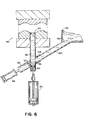
- FIG. 6 An alternative embodiment of the invention in a vertical die casting system is show in Fig. 6.
- the vertical system includes a die 80, a hydraulic shot cylinder 82, plunger 84, shot sleeve 86, hydraulic cylinder 88, filling cylinder 90, and slide valve 92.
- the hydraulic cylinder 82, plunger 84, and shot sleeve 80 are coaxial and vertically oriented with the upper end opening 94 of the shot sleeve in fluid communication with the cavity of the die.
- filling cylinder 90 is situated with its axis angularly offset to the shot sleeve axis and spaced apart from the shot sleeve axis where the axes cross. Filling cylinder 90 overlaps and partially intersects the shot sleeve 86 such that the internal bores of both are in fluid communication through a filling opening or hole 96.
- Fig. 6 further illustrates an alternative means for introducing molten metal into the filling cylinder which eliminates the need for ladling and seals the filling system from the atmosphere.
- the axis of the filling cylinder 90 is tilted upwardly toward a reservoir 98 of molten metal.
- the lower extent of the reservoir 98 is formed with an opening 100 which leads to a downwardly sloping passage 102.
- the lower end of the passage 102 is connected to the upper end opening 104 of the filling cylinder 90.
- hydraulic cylinder 88 extends the slide valve 92 to seal off the filling hole 96.
- Slide valve 92 is formed with a recess (not shown) similarly to the recess 70 shown in Fig. 5a to allow the plunger 84 to pass the filling hole 96 without interference.
- the invention is easily adaptable to convert a conventional die cast apparatus to squeeze cast apparatus in which relatively high pressures are developed in the injected molten metal.
- Conventional intensification systems may be used with the invention.
- Existing shot stroke adjustment is used to adjust shot size.
- the invention is suitable for casting steel, aluminium and magnesium, as well as other metallic and nonmetallic materials. The movements of the plunger and the slide valve keep the pouring paths clear.
Landscapes
- Engineering & Computer Science (AREA)
- Mechanical Engineering (AREA)
- Injection Moulding Of Plastics Or The Like (AREA)
Applications Claiming Priority (2)
| Application Number | Priority Date | Filing Date | Title |
|---|---|---|---|
| US805033 | 1991-12-11 | ||
| US07/805,033 US5205338A (en) | 1991-12-11 | 1991-12-11 | Closed shot die casting |
Publications (2)
| Publication Number | Publication Date |
|---|---|
| EP0546664A1 true EP0546664A1 (fr) | 1993-06-16 |
| EP0546664B1 EP0546664B1 (fr) | 1997-10-01 |
Family
ID=25190531
Family Applications (1)
| Application Number | Title | Priority Date | Filing Date |
|---|---|---|---|
| EP92309573A Expired - Lifetime EP0546664B1 (fr) | 1991-12-11 | 1992-10-20 | Cylindre fermé de remplissage pour coulée sous pression |
Country Status (7)
| Country | Link |
|---|---|
| US (1) | US5205338A (fr) |
| EP (1) | EP0546664B1 (fr) |
| JP (1) | JPH084902B2 (fr) |
| CA (1) | CA2068058C (fr) |
| DE (1) | DE69222510T2 (fr) |
| ES (1) | ES2109319T3 (fr) |
| MX (1) | MX9204662A (fr) |
Cited By (1)
| Publication number | Priority date | Publication date | Assignee | Title |
|---|---|---|---|---|
| CN104507599A (zh) * | 2012-06-04 | 2015-04-08 | 格布尔.克拉尔曼有限责任公司 | 喷射压力装置内的金属熔融物的输送设备 |
Families Citing this family (20)
| Publication number | Priority date | Publication date | Assignee | Title |
|---|---|---|---|---|
| US5529110A (en) * | 1994-07-25 | 1996-06-25 | Nelson Metal Products Corporation | Rotary actuated closed shot die casting |
| US5630463A (en) * | 1994-12-08 | 1997-05-20 | Nelson Metal Products Corporation | Variable volume die casting shot sleeve |
| JP3817786B2 (ja) * | 1995-09-01 | 2006-09-06 | Tkj株式会社 | 合金製品の製造方法及び装置 |
| US5730202A (en) * | 1996-03-18 | 1998-03-24 | Nelson Metal Products Corporation | Constant volume shot sleeve |
| US5983976A (en) | 1998-03-31 | 1999-11-16 | Takata Corporation | Method and apparatus for manufacturing metallic parts by fine die casting |
| US6135196A (en) | 1998-03-31 | 2000-10-24 | Takata Corporation | Method and apparatus for manufacturing metallic parts by injection molding from the semi-solid state |
| US6474399B2 (en) | 1998-03-31 | 2002-11-05 | Takata Corporation | Injection molding method and apparatus with reduced piston leakage |
| US6540006B2 (en) | 1998-03-31 | 2003-04-01 | Takata Corporation | Method and apparatus for manufacturing metallic parts by fine die casting |
| JP3268268B2 (ja) * | 1998-05-26 | 2002-03-25 | 幸久 長子 | 自動給湯射出装置 |
| US6666258B1 (en) | 2000-06-30 | 2003-12-23 | Takata Corporation | Method and apparatus for supplying melted material for injection molding |
| US6742570B2 (en) | 2002-05-01 | 2004-06-01 | Takata Corporation | Injection molding method and apparatus with base mounted feeder |
| US6805189B2 (en) * | 2002-10-30 | 2004-10-19 | Howmet Research Corporation | Die casting |
| US6945310B2 (en) | 2003-05-19 | 2005-09-20 | Takata Corporation | Method and apparatus for manufacturing metallic parts by die casting |
| US6951238B2 (en) * | 2003-05-19 | 2005-10-04 | Takata Corporation | Vertical injection machine using gravity feed |
| US6880614B2 (en) * | 2003-05-19 | 2005-04-19 | Takata Corporation | Vertical injection machine using three chambers |
| KR100578257B1 (ko) * | 2003-06-03 | 2006-05-15 | 고동근 | 다이케스팅기 |
| KR100554093B1 (ko) * | 2004-02-04 | 2006-02-22 | 주식회사 나노캐스트코리아 | 반응고 성형장치 |
| DE102008037200B4 (de) * | 2008-08-11 | 2015-07-09 | Aap Implantate Ag | Verwendung eines Druckgussverfahrens zur Herstellung eines Implantats aus Magnesium sowie Magnesiumlegierung |
| US20170136527A1 (en) * | 2015-11-16 | 2017-05-18 | GM Global Technology Operations LLC | High pressure die cast machine |
| CN106984794B (zh) * | 2017-03-31 | 2019-07-09 | 福州大学 | 一种异种双金属复合板共挤压制备方法 |
Citations (3)
| Publication number | Priority date | Publication date | Assignee | Title |
|---|---|---|---|---|
| GB475543A (en) * | 1936-02-21 | 1937-11-22 | Karl Friedrich Wagner | Improvements in compression casting-machines for easily oxidizable metals |
| EP0226830A2 (fr) * | 1985-11-26 | 1987-07-01 | Akio Nakano | Installation d'injection dans une machine à couler sous pression à chambre chaude |
| WO1992004147A1 (fr) * | 1990-08-30 | 1992-03-19 | Techmire Ltee./Ltd. | Machine de moulage sous pression de magnesium |
Family Cites Families (18)
| Publication number | Priority date | Publication date | Assignee | Title |
|---|---|---|---|---|
| US359757A (en) * | 1887-03-22 | Method of making plumbersj traps | ||
| BE565457A (fr) * | ||||
| US2137764A (en) * | 1936-03-19 | 1938-11-22 | Wagner Karl Friedrich | Apparatus for casting metal under pressure |
| DE935147C (de) * | 1954-01-24 | 1955-11-10 | Mahle Werk G M B H | Pressgiessmaschine |
| US2972172A (en) * | 1958-01-22 | 1961-02-21 | Alfred P Federman | Method for feeding liquid casting material into an article mold |
| US3019495A (en) * | 1958-05-28 | 1962-02-06 | Litemetal Dicast Inc | Die casting |
| US3292218A (en) * | 1965-04-29 | 1966-12-20 | J A Kozma Company | Automatic metal injection system |
| US3646990A (en) * | 1969-10-10 | 1972-03-07 | Raymond E Cross | Die casting machine |
| US3810505A (en) * | 1970-12-07 | 1974-05-14 | R Cross | Die casting method |
| US3791440A (en) * | 1970-12-07 | 1974-02-12 | R Cross | Die casting method |
| JPS5227106A (en) * | 1975-08-27 | 1977-03-01 | Hitachi Ltd | Railway train operation control system |
| JPS5843177B2 (ja) * | 1979-01-26 | 1983-09-26 | 本田技研工業株式会社 | 縦型ダイカストマシンにおける溶湯の充填方法 |
| JPS56102365A (en) * | 1980-01-21 | 1981-08-15 | Honda Motor Co Ltd | Method of filling molten metal in vertical type die casting machine |
| JPS58196159A (ja) * | 1982-05-12 | 1983-11-15 | Honda Motor Co Ltd | 溶湯鍛造用金型 |
| US4505318A (en) * | 1982-06-04 | 1985-03-19 | Toyoto Jidosha Kogyo Kabushiki Kaisha | Vertical type pressure casting method |
| JPS60102259A (ja) * | 1983-11-09 | 1985-06-06 | Honda Motor Co Ltd | 高圧凝固鋳造装置 |
| US4614463A (en) * | 1985-09-11 | 1986-09-30 | Hughes Chesley P | Cutter having removable cutting blades |
| JPS62286659A (ja) * | 1986-06-05 | 1987-12-12 | Toshiba Mach Co Ltd | 給湯装置 |
-
1991
- 1991-12-11 US US07/805,033 patent/US5205338A/en not_active Expired - Fee Related
-
1992
- 1992-05-06 CA CA002068058A patent/CA2068058C/fr not_active Expired - Fee Related
- 1992-08-12 MX MX9204662A patent/MX9204662A/es not_active IP Right Cessation
- 1992-10-20 EP EP92309573A patent/EP0546664B1/fr not_active Expired - Lifetime
- 1992-10-20 DE DE69222510T patent/DE69222510T2/de not_active Expired - Fee Related
- 1992-10-20 ES ES92309573T patent/ES2109319T3/es not_active Expired - Lifetime
- 1992-11-05 JP JP4295884A patent/JPH084902B2/ja not_active Expired - Lifetime
Patent Citations (3)
| Publication number | Priority date | Publication date | Assignee | Title |
|---|---|---|---|---|
| GB475543A (en) * | 1936-02-21 | 1937-11-22 | Karl Friedrich Wagner | Improvements in compression casting-machines for easily oxidizable metals |
| EP0226830A2 (fr) * | 1985-11-26 | 1987-07-01 | Akio Nakano | Installation d'injection dans une machine à couler sous pression à chambre chaude |
| WO1992004147A1 (fr) * | 1990-08-30 | 1992-03-19 | Techmire Ltee./Ltd. | Machine de moulage sous pression de magnesium |
Cited By (2)
| Publication number | Priority date | Publication date | Assignee | Title |
|---|---|---|---|---|
| CN104507599A (zh) * | 2012-06-04 | 2015-04-08 | 格布尔.克拉尔曼有限责任公司 | 喷射压力装置内的金属熔融物的输送设备 |
| CN104507599B (zh) * | 2012-06-04 | 2016-08-24 | 格布尔.克拉尔曼有限责任公司 | 喷射压力装置内的金属熔融物的输送设备 |
Also Published As
| Publication number | Publication date |
|---|---|
| CA2068058C (fr) | 1996-12-17 |
| DE69222510D1 (de) | 1997-11-06 |
| ES2109319T3 (es) | 1998-01-16 |
| CA2068058A1 (fr) | 1993-06-12 |
| US5205338A (en) | 1993-04-27 |
| JPH084902B2 (ja) | 1996-01-24 |
| DE69222510T2 (de) | 1998-04-16 |
| MX9204662A (es) | 1993-06-01 |
| EP0546664B1 (fr) | 1997-10-01 |
| JPH05212520A (ja) | 1993-08-24 |
Similar Documents
| Publication | Publication Date | Title |
|---|---|---|
| EP0546664B1 (fr) | Cylindre fermé de remplissage pour coulée sous pression | |
| KR910009623B1 (ko) | 주조장치용의 가압장치 | |
| US20070215308A1 (en) | Vertical Casting Apparatus and Vertical Casting Method | |
| CN102527997B (zh) | 受控压力铸造 | |
| JP3418027B2 (ja) | 溶湯鍛造装置 | |
| US5601136A (en) | Inclined die cast shot sleeve system | |
| US1961941A (en) | Die-casting | |
| CA2189172C (fr) | Methode de lubrification de machine a couler sous pression a l'aide d'un lubrifiant unitise | |
| US5207264A (en) | Vertical die casting machine | |
| EP0177257B1 (fr) | Machine de coulée | |
| US5730202A (en) | Constant volume shot sleeve | |
| GB1013296A (en) | Method of an apparatus for casting and working metal | |
| AU638902B1 (en) | Closed shot die casting system | |
| MXPA96005040A (en) | Lubrication method for pressure machine with unita lubricant | |
| US5971057A (en) | Injection molding machine and injection molding method | |
| US20040231821A1 (en) | Vertical injection machine using three chambers | |
| US6062294A (en) | Injection molding machine and injection molding method | |
| US2804666A (en) | Pressure casting piston machines | |
| US6250368B1 (en) | Casting mold for producing a fiber-reinforced composite article by die-casting process | |
| PL202883B1 (pl) | Sposób pracy gorącokomorowej maszyny ciśnieniowej i gorącokomorowa maszyna ciśnieniowa | |
| US3700025A (en) | Method of casting quiet melts | |
| US5657833A (en) | Self-contained unitized lubricant delivery apparatus | |
| EP0694357B1 (fr) | Appareil à coulée sous pression | |
| EP1894648A1 (fr) | Procédé de coulée à basse pression et dispositif correspondant | |
| MXPA04012660A (es) | Metodo y aparato para inyectar metal fundido dentro de un molde. |
Legal Events
| Date | Code | Title | Description |
|---|---|---|---|
| PUAI | Public reference made under article 153(3) epc to a published international application that has entered the european phase |
Free format text: ORIGINAL CODE: 0009012 |
|
| AK | Designated contracting states |
Kind code of ref document: A1 Designated state(s): CH DE ES FR GB IT LI |
|
| 17P | Request for examination filed |
Effective date: 19931214 |
|
| 17Q | First examination report despatched |
Effective date: 19950828 |
|
| GRAG | Despatch of communication of intention to grant |
Free format text: ORIGINAL CODE: EPIDOS AGRA |
|
| GRAH | Despatch of communication of intention to grant a patent |
Free format text: ORIGINAL CODE: EPIDOS IGRA |
|
| GRAH | Despatch of communication of intention to grant a patent |
Free format text: ORIGINAL CODE: EPIDOS IGRA |
|
| GRAA | (expected) grant |
Free format text: ORIGINAL CODE: 0009210 |
|
| AK | Designated contracting states |
Kind code of ref document: B1 Designated state(s): CH DE ES FR GB IT LI |
|
| REG | Reference to a national code |
Ref country code: CH Ref legal event code: EP |
|
| REF | Corresponds to: |
Ref document number: 69222510 Country of ref document: DE Date of ref document: 19971106 |
|
| ITF | It: translation for a ep patent filed |
Owner name: BARZANO' E ZANARDO ROMA S.P.A. |
|
| REG | Reference to a national code |
Ref country code: CH Ref legal event code: NV Representative=s name: KIRKER & CIE SA |
|
| ET | Fr: translation filed | ||
| REG | Reference to a national code |
Ref country code: ES Ref legal event code: FG2A Ref document number: 2109319 Country of ref document: ES Kind code of ref document: T3 |
|
| PLBE | No opposition filed within time limit |
Free format text: ORIGINAL CODE: 0009261 |
|
| STAA | Information on the status of an ep patent application or granted ep patent |
Free format text: STATUS: NO OPPOSITION FILED WITHIN TIME LIMIT |
|
| 26N | No opposition filed | ||
| PGFP | Annual fee paid to national office [announced via postgrant information from national office to epo] |
Ref country code: GB Payment date: 20000918 Year of fee payment: 9 |
|
| PGFP | Annual fee paid to national office [announced via postgrant information from national office to epo] |
Ref country code: FR Payment date: 20001009 Year of fee payment: 9 |
|
| PGFP | Annual fee paid to national office [announced via postgrant information from national office to epo] |
Ref country code: ES Payment date: 20001017 Year of fee payment: 9 |
|
| PGFP | Annual fee paid to national office [announced via postgrant information from national office to epo] |
Ref country code: DE Payment date: 20001030 Year of fee payment: 9 |
|
| PGFP | Annual fee paid to national office [announced via postgrant information from national office to epo] |
Ref country code: CH Payment date: 20010103 Year of fee payment: 9 |
|
| PG25 | Lapsed in a contracting state [announced via postgrant information from national office to epo] |
Ref country code: GB Free format text: LAPSE BECAUSE OF NON-PAYMENT OF DUE FEES Effective date: 20011020 |
|
| PG25 | Lapsed in a contracting state [announced via postgrant information from national office to epo] |
Ref country code: ES Free format text: LAPSE BECAUSE OF NON-PAYMENT OF DUE FEES Effective date: 20011021 |
|
| PG25 | Lapsed in a contracting state [announced via postgrant information from national office to epo] |
Ref country code: LI Free format text: LAPSE BECAUSE OF NON-PAYMENT OF DUE FEES Effective date: 20011031 Ref country code: CH Free format text: LAPSE BECAUSE OF NON-PAYMENT OF DUE FEES Effective date: 20011031 |
|
| REG | Reference to a national code |
Ref country code: GB Ref legal event code: IF02 |
|
| GBPC | Gb: european patent ceased through non-payment of renewal fee |
Effective date: 20011020 |
|
| REG | Reference to a national code |
Ref country code: CH Ref legal event code: PL |
|
| PG25 | Lapsed in a contracting state [announced via postgrant information from national office to epo] |
Ref country code: FR Free format text: LAPSE BECAUSE OF NON-PAYMENT OF DUE FEES Effective date: 20020628 |
|
| PG25 | Lapsed in a contracting state [announced via postgrant information from national office to epo] |
Ref country code: DE Free format text: LAPSE BECAUSE OF NON-PAYMENT OF DUE FEES Effective date: 20020702 |
|
| REG | Reference to a national code |
Ref country code: FR Ref legal event code: ST |
|
| REG | Reference to a national code |
Ref country code: ES Ref legal event code: FD2A Effective date: 20021113 |
|
| PG25 | Lapsed in a contracting state [announced via postgrant information from national office to epo] |
Ref country code: IT Free format text: LAPSE BECAUSE OF NON-PAYMENT OF DUE FEES;WARNING: LAPSES OF ITALIAN PATENTS WITH EFFECTIVE DATE BEFORE 2007 MAY HAVE OCCURRED AT ANY TIME BEFORE 2007. THE CORRECT EFFECTIVE DATE MAY BE DIFFERENT FROM THE ONE RECORDED. Effective date: 20051020 |