EP0546341A1 - Coin testing method - Google Patents
Coin testing method Download PDFInfo
- Publication number
- EP0546341A1 EP0546341A1 EP92119438A EP92119438A EP0546341A1 EP 0546341 A1 EP0546341 A1 EP 0546341A1 EP 92119438 A EP92119438 A EP 92119438A EP 92119438 A EP92119438 A EP 92119438A EP 0546341 A1 EP0546341 A1 EP 0546341A1
- Authority
- EP
- European Patent Office
- Prior art keywords
- coin
- sensor
- light
- circular path
- measured values
- Prior art date
- Legal status (The legal status is an assumption and is not a legal conclusion. Google has not performed a legal analysis and makes no representation as to the accuracy of the status listed.)
- Withdrawn
Links
Images

Classifications
-
- G—PHYSICS
- G07—CHECKING-DEVICES
- G07D—HANDLING OF COINS OR VALUABLE PAPERS, e.g. TESTING, SORTING BY DENOMINATIONS, COUNTING, DISPENSING, CHANGING OR DEPOSITING
- G07D5/00—Testing specially adapted to determine the identity or genuineness of coins, e.g. for segregating coins which are unacceptable or alien to a currency
- G07D5/005—Testing the surface pattern, e.g. relief
-
- G—PHYSICS
- G07—CHECKING-DEVICES
- G07D—HANDLING OF COINS OR VALUABLE PAPERS, e.g. TESTING, SORTING BY DENOMINATIONS, COUNTING, DISPENSING, CHANGING OR DEPOSITING
- G07D5/00—Testing specially adapted to determine the identity or genuineness of coins, e.g. for segregating coins which are unacceptable or alien to a currency
Definitions
- the invention relates to a method for checking a coin, in which measured values are recorded sequentially with at least one optical sensor along a concentric circular path lying on a main surface of the coin and compared with a stored detection pattern.
- the invention also relates to an apparatus for performing this method.
- EP 0245805-A2 describes a coin validator in which the coin is held between two coils and the characteristic attenuation of a high-frequency signal caused by the coin is detected.
- the disadvantage of the inductive measuring principle is that only an integral measurement can be carried out.
- Devices have therefore been developed in which the coin is scanned optically.
- the optical sensor allows the scanning of a precisely defined point on the surface of the coin.
- a coin validator is known in which a main surface of the coin is scanned with an optical sensor on a concentric circular path. The coin is guided past the sensor on a runway under the effect of its own weight. The scanning on a circular path is brought about by the fact that the runway has the form of a loop. The optical sampling point is located in the center of the loop.
- the problem with this coin validator is that the coin performs a combined rolling and sliding movement, which results in "smearing" of the detected signal.
- the object of the invention is now to provide a method for checking coins that can be carried out with simple means and at the same time allows a detailed analysis of the coin. It is also an object of the invention to provide an apparatus for performing the method.
- the solution is that in a method of the type mentioned at the outset, a relative angle of rotation between the coin and the sensor is detected, so that each measured value can be assigned a precisely defined relative angular position.
- the main advantage over the known methods is that the measured values have a precisely defined relationship to the degree of rotation of the coin.
- the constant phase shift for all measured values can be eliminated very easily by calculation.
- the angle of rotation can e.g. are detected in that the rotation of the holder fixing the coin or. of the sensor scanning the coin is only monitored or is specifically controlled.
- the measured values are preferably recorded in such a way that they lie on the circular path in exactly equidistant positions. Each measured value corresponds to a clearly identifiable measuring point.
- the measuring points advantageously cover the circular path completely and completely. Equidistantly arranged measuring points result in a particularly simple signal evaluation.
- a device for carrying out the method has an optical sensor for sequential recording of measured values along the concentric circular path and first means for comparing the recorded measured values with a recognition pattern.
- a device is further characterized by a holder for holding the coin, second means for generating a relative movement between the coin held in the holder and the optical sensor and third means for monitoring the generated relative movement.
- the device according to the invention manages with a single optical sensor that is focused on one point.
- the circular path is scanned successively (continuously or step by step) with the single sensor.
- only one sensor (with point-shaped tracing rich) needed.
- two or more circular paths (with different radii) can also be scanned at the same time with a corresponding number of sensors.
- An important aspect of the invention is that the relative movement between the coin and the sensor is kept under control. This is achieved in that the coin is clamped centered in a special holder and that this holder and not the coin alone is set in rotation.
- the mechanics with which the holder is rotated can be manufactured by the designer with the desired accuracy. In other words, the "mechanical interface", with which the movement of the coin is controlled, can be handled much better with the invention than with the prior art.
- the relative movement that has taken place is e.g. monitored with a control circuit or. registered and / or controlled. If a stepper motor is used to generate the relative movement, then the movement is monitored by means of the control pulses.
- An angle disk can also be provided on the rotating part, with which the degree of rotation can be detected and a measured value can be recorded at the desired location.
- each coin is characterized by a series of pairs of values, one part of a pair of values being a detected reflection value and the other an angular position.
- the coin can be identified using this pattern.
- the second means preferably rotate the sensor around the center of the coin on the predetermined circular path. So the coin is held and only the sensor is moved. From a purely kinematic point of view, it may be meaningless whether the sensor rotates and the holder rests with the coin or, conversely, the holder is rotated and the sensor rests. For design reasons, it is usually better to rotate the sensor.
- the holder is relatively complex because it has to be able to center different coins precisely fixed.
- the optical sensor is preferably constructed in the manner of a light barrier.
- a light-emitting semiconductor element in particular a light-emitting diode as a transmitter
- a light-sensitive semiconductor element in particular a phototransistor as a receiver
- small optics the light-emitting diode and phototransistor are set to a common focus point in the sense of a reflection detector.
- a light barrier element with a working distance of a few millimeters, e.g. 5 mm.
- the relative movement is advantageously generated with a stepper motor. This represents a simple and precise means of generating and monitoring the relative movement.
- the sensor is fixed on a carrier which is rotated in a plane parallel to the main surface of the coin.
- the carrier is held at a defined distance from the coin surface by an axially arranged spacer.
- the carrier is axially displaceable. To scan the circular path, the spacer element is brought into contact with the coin and withdrawn to replace the coin.
- the carrier is fixed on the axis driven by the stepper motor and is moved axially with the stepper motor together with an electromagnetic linear drive.
- the stroke of the axial movement need not be very large.
- the axis on which the carrier is fixed can be an extension of the stepper motor axis or a separate axis driven by a gear.
- the sensor is designed so that there is a beam diameter of 0.1 to 0.3 mm at the focal point. If the beam diameter is too small, the measurement becomes sensitive to dirt on the surface or (irrelevant) scratches in the coin. If, on the other hand, it is too large, the desired fine resolution can no longer be achieved. Finally, it should also be noted that the smaller the beam diameter, the more sensitive the measurement to centering errors. These considerations have shown that a diameter in the order of 0.2 mm is particularly advantageous.
- a differential light detection can be carried out.
- a control circuit modulates the intensity of the light-emitting diode, and a suitable circuit registers the difference value in the reflection component.
- a coin 1 is scanned on a concentric circular path 2 with a predetermined radius.
- a series IV of measuring points 3.1, 3.2 ... 3.N is scanned with an optical sensor (described later).
- the measuring points have exactly defined relative angular positions to each other.
- the two measuring points 3.1 and 3.2 are at a precisely determined angle a ; spaced.
- the absolute position of a measuring point ie the position in relation to the minted image of the coin on the surface of the coin, on the other hand, is not known a priori. However, it can be determined retrospectively when all measuring points 3.1 to 3.N have been recorded and evaluated.
- the "phase error" is the same for all measuring points. Basically, it can be calculated without problems (e.g. using a correlation method), but in practice it is of no interest.
- the measuring points 3.1 to 3.N have a predetermined diameter, which is determined by the sensor. Typically, the measuring points 3.1 to 3.N are more or less circular and have a diameter between 0.1 and 0.3 mm. The measurement points 3.1 to 3.N are preferably so close to one another that they at least touch one another, if not partially overlap. The circular path 2 is then completely covered.
- the recognition pattern of a coin therefore consists of a series of pairs of values (angle, intensity).
- the difference compared to the prior art could be expressed in that, in the known scanning methods, the time and not the angle would be plotted on the abscissa.
- the time interval is generally known, but not the angular one. As already mentioned, this is due to the fact that, in the prior art, there is an uncontrollable slip when rotating the coin because of the rolling movement which cannot be precisely controlled.
- the method according to the invention is based on a reflection measurement.
- the measuring point is illuminated with a small light source and the light reflected at a predetermined angle is measured.
- the intensity of the reflected light depends on the one hand on the curvature or inclination of the illuminated surface and on the other hand on the distance between the sensor and the surface of the coin.
- the quality of the surface and the degree of contamination also play a role. It is important for the invention that all those influences that are not caused by the embossing itself can be eliminated. These include e.g. Errors in the beam geometry or effects of scattered light. Geometric errors can be kept under control by means of a radiation geometry that is invariable with respect to the center of the coin and by precise mechanics. Stray light influences are preferably eliminated by a differential light measurement, as will be explained below with reference to FIG. 3.
- S 1 is, for example, a square wave signal with a frequency of a few kHz (eg 5 kHz).
- t 1 the coin is in a certain angular position.
- a measurement must now be carried out within a certain time interval t 2 -ti.
- the reflected light component is therefore measured in a selected interval t 12 -t 11 , in which the measuring point is illuminated by the light source.
- the measured value determined in this way contains the proportion of useful light and scattered light.
- a scattered light measurement is carried out in a second interval of the same length t 13 -t12. The difference is then determined from the two measured values. This can already be done in the sensor, so that a measurement value adjusted for stray light can be read out. The difference can, however, just as well be made in a separate evaluation circuit.
- the measured values are preferably standardized in terms of amplitude.
- the normalization can be based on the mean, the variance or some other general weighting.
- the recorded series of measured values is evaluated using methods known per se. It can e.g. can be cross-correlated with a stored recognition pattern. Performing an integral transformation (e.g. Fourier transformation) would be somewhat more complex, but would be useful in principle. The calculation of the center of gravity or the determination of the minima and maxima would be less computationally intensive, but also less differentiated.
- an integral transformation e.g. Fourier transformation
- the coin 1 is fixed in a holder 4.
- Guide plates 5.1, 5.2 overlap the coin 1 on the edge and thus prevent it from falling out.
- the holder 4 is designed such that coins with different diameters always lie at the same point with their center.
- Such a coin holder is known for example from EP 0245805 cited at the beginning.
- other coin holders are also conceivable.
- the coin can also be centered between two arms which can be moved in opposite directions and are provided with V-shaped cutouts.
- a structure is connected to the holder 4, which essentially serves to move the optical sensor along the concentric circular path.
- a carrier plate 7 is provided, the support elements 6.1 to 6.3 with the bracket 4 and. whose guide plates 5.1 and 5.2 are connected.
- the carrier plate 7 is parallel to the surface of the coin.
- two guide rods 8.1 and 8.2 protrude vertically to the rear.
- a motor mount 12 is guided on these two guide rods 8.1 and 8.2.
- the motor mount 12 has appropriately designed bores with linear ball bearings 10.1 and 10.2 arranged therein. The motor mount 12 can therefore be moved back and forth perpendicular to the surface of the coin.
- a stepper motor 13 is attached to the motor mount 12. Its axis is perpendicular to the surface of the coin.
- the support plate 7 has a hole for an extension piece 14 at a corresponding point, which is screwed onto the axis of the stepping motor 13.
- the extension piece 14 continues the axis up to the surface of the coin.
- a sensor carrier 15 is attached to it and can be rotated in a plane parallel to the coin surface around the center of the coin.
- the optical sensor 19 e.g. a light barrier element
- a spacer element 16 is attached to the front of the extension piece 14. It is located on the axis of rotation and defines the distance between the sensor 19 and the surface of the coin 1 during the scanning.
- Fig. 6 the two guide rods 8.1 and 8.2 are drawn on the side, on which the motor bracket 12 slides. 6 above and below, two electromagnets 17.1 and 17.2 are provided. They are therefore offset by 90 ° with respect to the axis of the stepping motor 13 with respect to the guide rods 8.1 and 8.2. They are there to pull the motor mount 12 and thus the stepper motor 13, the axis extension piece 14, the sensor mount 15 and the spacer element 16 against the force of the coil springs 9.1 and 9.2 to the front, ie against the coin 1.
- Two anchors 18.1 and 18.2 are therefore provided, which are fastened to the carrier plate 7 and can be drawn into themselves by the electromagnets 17.1 and 17.2.
- the spacer element 16 is pressed onto the main surface of the coin 1.
- the coin 1 is additionally fixed in this way.
- a defined distance between the sensor and the main surface of the coin 1 to be scanned is created.
- Fig. 7 shows a detailed view of the sensor carrier 15 with the sensor 19 held by it.
- the sensor carrier 15 is, for example, a plate which, respectively, on the axis of the stepping motor. is screwed onto the extension piece 14.
- the sensor 19 itself is preferably a commercially available light barrier module. Such includes a light emitting diode 21, a phototransistor 22 and Lin sen 24 and 25, which ensure that light emitting diode 21 and phototransistor 22 are aligned to a common focus point. In principle, the small reflections of the embossing characteristically impair the optimal reflection. It is obvious that the coin signal is falsified if the sensor 19 is not at a constant mean distance from the surface of the coin.
- a very important measure is therefore that the sensor carrier 15 is moved absolutely parallel to the coin 1.
- a second preferred measure consists in that a plastic cap 20 is fastened on the axis of rotation, which is pressed onto the scanned main surface of the coin 1 by the force of the electromagnets 17.1 and 17.2.
- a circular path is completely scanned with one and the same sensor.
- the sensor carrier 15 must be rotated by at least 360. It must be guaranteed in every angular position that the sensor 19 can be controlled with a control signal (S1) and the corresponding measured values can be recorded.
- a connection cable 23 with the supply and removal wires around the axis, respectively. the extension piece 14 passed around in several loose turns. In this way, free cable length is created which is picked up during the scanning (i.e. during the rotation). can be delivered.
- the flexural rigidity of the cable material keeps the connecting cable 23 spirally spaced from the extension piece 14. The cable will therefore not get jammed or tangled.
- measuring points are advantageous, but not mandatory. If necessary, it is easily possible to determine interim values by interpolation. It is of course important that the distances between the measuring points are chosen so that no relevant points in the coinage pattern of the coin to be scanned can be skipped.
- the checked coins are sorted by the machine.
- a trolley moves back and forth between the opening slots of various coin collecting containers and drops the coin at a suitable point.
- the linear movement of the trolley, on which a suitably rotatable sensor is mounted can be converted into a rotary movement using a rack and pinion gear.
- a stepper motor arranged on the carriage itself for rotating the sensor can then be omitted or. be replaced by a rack and pinion gear.
- the linear advance of the sensor for the purpose of setting the desired working distance can also be effected by means other than electromagnets.
- a linear motor or stepper motor can be used. If a precisely defined distance can be achieved without the preferred distance element, then the linear feed can be dispensed with altogether.
- the structural details are not essential for the success of the invention. For a person skilled in the art, modifications result from the entirety of the description.
- the invention preferably works with one sensor per circular path. To improve the series of measured values, two or more sensors can also be "rotated" at the same time.
- an arrangement with a light source and a plurality of photodetectors measuring simultaneously at different angles can also be provided.
- the coin can also be illuminated over the whole area and scanned locally.
- Several sensors can also be scanned on the same circular path, the individual sensors being offset by the same angle (e.g. 4 sensors offset by 90).
- a relative rotation between coin and sensor arrangement by a fraction of 360 e.g. by 900 is sufficient to detect an entire circular path.
- a single sensor then scans only one sector of the circular path.
- the invention is characterized by high-resolution embossing recognition.
- the device combines high precision and spatial compactness. Uncontrolled degrees of freedom and therefore sources of error are largely eliminated.
Landscapes
- Physics & Mathematics (AREA)
- General Physics & Mathematics (AREA)
- Testing Of Coins (AREA)
Abstract
Description
Die Erfindung bezieht sich auf ein Verfahren zum Prüfen einer Münze, bei welchem mit mindestens einem optischen Sensor entlang einer auf einer Hauptfläche der Münze liegenden konzentrischen Kreisbahn sequentiell Messwerte aufgenommen und mit einem abgespeicherten Erkennungsmuster verglichen werden. Die Erfindung betrifft auch eine Vorrichtung zur Durchführung dieses Verfahrens.The invention relates to a method for checking a coin, in which measured values are recorded sequentially with at least one optical sensor along a concentric circular path lying on a main surface of the coin and compared with a stored detection pattern. The invention also relates to an apparatus for performing this method.
Seit langem sind Verfahren zum Prüfen von Münzen auf dem Wege einer induktiven Messung bekannt. In der EP 0245805-A2 wird beispielsweise ein Münzenprüfer beschrieben, bei dem die Münze zwischen zwei Spulen festgehalten und die durch die Münze bedingte charakteristische Dämpfung eines Hochfrequenzsignals detektiert wird.Methods for checking coins by inductive measurement have been known for a long time. EP 0245805-A2, for example, describes a coin validator in which the coin is held between two coils and the characteristic attenuation of a high-frequency signal caused by the coin is detected.
Der Nachteil beim induktiven Messprinzip liegt darin, dass nur eine integrale Messung durchgeführt werden kann. Es sind deshalb Vorrichtungen entwickelt worden, bei denen die Münze auf optischem Wege abgetastet wird. Im Gegensatz zum induktiven Sensor erlaubt der optische Sensor die Abtastung einer exakt definierten Stelle auf der Oberfläche der Münze. Aus der US 3,921,003 ist ein Münzprüfer bekannt, bei welchem eine Hauptfläche der Münze mit einem optischen Sensor auf einer konzentrischen Kreisbahn abgetastet wird. Die Münze wird dabei auf einer Rollbahn unter der Wirkung ihres eigenen Gewichts am Sensor vorbei geführt. Die Abtastung auf einer Kreisbahn wird dadurch bewirkt, dass die Rollbahn die Form eines Loopings hat. Im Zentrum des Loopings befindet sich der optische Abtastpunkt. Das Problem bei diesem Münzprüfer liegt darin, dass die Münze eine kombinierte Roll- und Gleitbewegung ausführt, was eine "Verschmierung" des detektierten Signals zur Folge hat.The disadvantage of the inductive measuring principle is that only an integral measurement can be carried out. Devices have therefore been developed in which the coin is scanned optically. In contrast to the inductive sensor, the optical sensor allows the scanning of a precisely defined point on the surface of the coin. From US 3,921,003 a coin validator is known in which a main surface of the coin is scanned with an optical sensor on a concentric circular path. The coin is guided past the sensor on a runway under the effect of its own weight. The scanning on a circular path is brought about by the fact that the runway has the form of a loop. The optical sampling point is located in the center of the loop. The problem with this coin validator is that the coin performs a combined rolling and sliding movement, which results in "smearing" of the detected signal.
Aus dem Artikel "Reconnaissance de relief: Les multiples possibilites de I'optoelectronique", mesure-regulation-automatisme, Februar 1981, S. 57-61, ist ein Verfahren bekannt, das die oben genannte Problematik gezielt umgeht. Bei diesem wird die Münze auf einem Teller rotiert und mit einem in radialer Richtung angeordneten Phototransistorarray abgetastet. Dadurch, dass die Münze durch eine ringförmige Lichtquelle beleuchtet wird und die Lichtintensität in der einzelnen Zelle des Phototransistorarrays aufintegriert resp. zeitlich gemittelt wird, wird von jeder Münze ein rotationsinvariantes Ringmuster aufgenommen, das als Erkennungszeichen dient. Die Unempfindlichkeit gegenüber Winkelverschiebungen muss durch ein nicht besonders differenziertes Erkennungsmuster erkauft werden. Zudem ist der optische (Abbildungssystem) und elektronische (Phototransistorarray) Aufwand verhältnismässig gross.From the article "Reconnaissance de relief: Les multiples possibilites de I'optoelectronique", mesure-regulation-automatisme, February 1981, pp. 57-61, a method is known which specifically avoids the above-mentioned problem. The coin is rotated on a plate and scanned with a photo transistor array arranged in the radial direction. The fact that the coin is illuminated by an annular light source and the light intensity in the individual cell of the phototransistor array is integrated or. is averaged over time, a rotation-invariant ring pattern is recorded from each coin, which serves as a distinguishing mark. The insensitivity to angular shifts must be bought through a not particularly differentiated detection pattern. In addition, the optical (imaging system) and electronic (phototransistor array) are relatively large.
Aufgabe der Erfindung ist es nun, ein Verfahren zum Prüfen von Münzen anzugeben, das mit einfachen Mitteln durchgeführt werden kann und zugleich eine detaillierte Analyse der Münze erlaubt. Ferner ist es Aufgabe der Erfindung, eine Vorrichtung zur Durchführung des Verfahrens anzugeben.The object of the invention is now to provide a method for checking coins that can be carried out with simple means and at the same time allows a detailed analysis of the coin. It is also an object of the invention to provide an apparatus for performing the method.
Gemäss der Erfindung besteht die Lösung darin, dass bei einem Verfahren der eingangs genannten Art ein relativer Rotationswinkel zwischen Münze und Sensor erfasst wird, so dass jedem Messwert eine exakt definierte relative Winkelposition zugeordnet werden kann.According to the invention, the solution is that in a method of the type mentioned at the outset, a relative angle of rotation between the coin and the sensor is detected, so that each measured value can be assigned a precisely defined relative angular position.
Der wesentliche Vorteil gegenüber den bekannten Verfahren liegt darin, dass die Messwerte eine exakt definierte Beziehung zum Rotationsgrad der Münze haben. Die für alle Messwerte konstante Phasenschiebung lässt sich rechnerisch sehr einfach eliminieren.The main advantage over the known methods is that the measured values have a precisely defined relationship to the degree of rotation of the coin. The constant phase shift for all measured values can be eliminated very easily by calculation.
Der Rotationswinkel kann z.B. dadurch erfasst werden, dass die Drehung der die Münze fixierenden Halterung resp. des die Münze abtastenden Sensors nur überwacht oder aber gezielt gesteuert wird.The angle of rotation can e.g. are detected in that the rotation of the holder fixing the coin or. of the sensor scanning the coin is only monitored or is specifically controlled.
Vorzugsweise werden die Messwerte so aufgenommen, dass sie auf der Kreisbahn in exakt äquidistanten Positionen liegen. Jeder Messwert entspricht einem eindeutig identifizierbaren Messpunkt. Mit Vorteil decken die Messpunkte die Kreisbahn lückenlos und vollständig ab. Aequidistant angeordnete Messpunkte ergeben eine besonders einfache Signalauswertung.The measured values are preferably recorded in such a way that they lie on the circular path in exactly equidistant positions. Each measured value corresponds to a clearly identifiable measuring point. The measuring points advantageously cover the circular path completely and completely. Equidistantly arranged measuring points result in a particularly simple signal evaluation.
Eine Vorrichtung zur Durchführung des Verfahrens weist einen optischen Sensor zum sequentiellen Aufnehmen von Messwerten entlang der konzentrischen Kreisbahn und erste Mittel zum Vergleichen der aufgenommenen Messwerte mit einem Erkennungsmuster auf. Gemäss der Erfindung zeichnet sich eine solche Vorrichtung ferner aus durch eine Halterung zum Festhalten der Münze, zweite Mittel zum Erzeugen einer Relativbewegung zwischen der in der Halterung festgehaltenen Münze und dem optischen Sensor und dritte Mittel zum Ueberwachen der erzeugten Relativbewegung.A device for carrying out the method has an optical sensor for sequential recording of measured values along the concentric circular path and first means for comparing the recorded measured values with a recognition pattern. According to the invention, such a device is further characterized by a holder for holding the coin, second means for generating a relative movement between the coin held in the holder and the optical sensor and third means for monitoring the generated relative movement.
Die erfindungsgemässe Vorrichtung kommt also im Prinzip mit einem einzigen optischen Sensor aus, der auf einen Punkt fokussiert ist. Mit dem einzigen Sensor wird die Kreisbahn sukzessive (kontinuierlich oder schrittweise) abgetastet. Gemäss der Erfindung wird pro abgetasteter Kreisbahn nur ein Sensor (mit punktförmigem Abtastbereich) benötigt. Selbstverständlich können auch gleichzeitig zwei oder mehr Kreisbahnen (mit unterschiedlichen Radien) mit entsprechend vielen Sensoren abgetastet werden.In principle, the device according to the invention manages with a single optical sensor that is focused on one point. The circular path is scanned successively (continuously or step by step) with the single sensor. According to the invention, only one sensor (with point-shaped tracing rich) needed. Of course, two or more circular paths (with different radii) can also be scanned at the same time with a corresponding number of sensors.
Ein wichtiger Aspekt der Erfindung besteht darin, dass die Relativbewegung zwischen Münze und Sensor genau unter Kontrolle gehalten wird. Dies wird dadurch erreicht, dass die Münze in einer speziellen Halterung zentriert eingespannt wird und dass diese Halterung und nicht etwa die Münze allein in Rotation versetzt wird. Die Mechanik, mit der die Halterung gedreht wird, kann vom Konstrukteur mit der gewünschten Genauigkeit hergestellt werden. Mit anderen Worten: Die "mechanische Schnittstelle", mit der die Bewegung der Münze kontrolliert wird, lässt sich bei der Erfindung viel besser im Griff halten als beim Stand der Technik.An important aspect of the invention is that the relative movement between the coin and the sensor is kept under control. This is achieved in that the coin is clamped centered in a special holder and that this holder and not the coin alone is set in rotation. The mechanics with which the holder is rotated can be manufactured by the designer with the desired accuracy. In other words, the "mechanical interface", with which the movement of the coin is controlled, can be handled much better with the invention than with the prior art.
Gemäss einem weiteren Merkmal der Erfindung wird die erfolgte Relativbewegung z.B. mit einer Steuerschaltung überwacht resp. registriert und/oder gesteuert. Wenn zur Erzeugung der Relativbewegung ein Schrittmotor verwendet wird, dann wird die Bewegung mittels der Ansteuerpulse überwacht. Es kann auch eine Winkelscheibe am drehenden Teil vorgesehen sein, mit welcher der Drehgrad detektiert und an der gewünschten Stelle ein Messwert aufgenommen werden kann.According to a further feature of the invention, the relative movement that has taken place is e.g. monitored with a control circuit or. registered and / or controlled. If a stepper motor is used to generate the relative movement, then the movement is monitored by means of the control pulses. An angle disk can also be provided on the rotating part, with which the degree of rotation can be detected and a measured value can be recorded at the desired location.
Gemäss der Erfindung wird also jede Münze mit einer Reihe von Wertepaaren charakterisiert, wobei ein Teil eines Wertepaares ein detektierter Reflexionswert und der andere eine Winkelposition ist. Ueber dieses Muster kann die Münze identifiziert werden.According to the invention, therefore, each coin is characterized by a series of pairs of values, one part of a pair of values being a detected reflection value and the other an angular position. The coin can be identified using this pattern.
Vorzugsweise drehen die zweiten Mittel den Sensor um den Mittelpunkt der Münze auf der vorgegebenen Kreisbahn. Die Münze wird also festgehalten, und nur der Sensor wird bewegt. Rein kinematisch betrachtet mag es zwar bedeutungslos sein, ob der Sensor rotiert und die Halterung mit der Münze ruht oder ob umgekehrt die Halterung rotiert wird und der Sensor ruht. Aus konstruktiven Gründen ist es aber meistens besser, den Sensor zu rotieren. Die Halterung ist nämlich relativ komplex, da sie verschiedene Münzen exakt fixiert zentrieren können muss.The second means preferably rotate the sensor around the center of the coin on the predetermined circular path. So the coin is held and only the sensor is moved. From a purely kinematic point of view, it may be meaningless whether the sensor rotates and the holder rests with the coin or, conversely, the holder is rotated and the sensor rests. For design reasons, it is usually better to rotate the sensor. The holder is relatively complex because it has to be able to center different coins precisely fixed.
Vorzugsweise ist der optische Sensor in der Art einer Lichtschranke aufgebaut. Das heisst, es ist ein lichtemittierendes Halbleiterelement, insbesondere eine Leuchtdiode als Sender und ein lichtempfindliches Halbleiterelement, insbesondere ein Phototransistor als Empfänger vorgesehen. Mit einer kleinen Optik (Linsen) werden Leuchtdiode und Phototransistor im Sinn eines Reflexionsdetektors auf einen gemeinsamen Fokuspunkt eingestellt. Solche Sensoren sind im Handel erhältlich. Für die Erfindung eignet sich ein Lichtschrankenelement mit einer Arbeitsdistanz von einigen wenigen Millimetern, z.B. 5 mm. Mit Vorteil wird die Relativbewegung mit einem Schrittmotor erzeugt. Dieser stellt ein einfaches und präzises Mittel zum Erzeugen und Ueberwachen der Relativbewegung dar.The optical sensor is preferably constructed in the manner of a light barrier. This means that a light-emitting semiconductor element, in particular a light-emitting diode as a transmitter, and a light-sensitive semiconductor element, in particular a phototransistor as a receiver, are provided. With small optics (lenses), the light-emitting diode and phototransistor are set to a common focus point in the sense of a reflection detector. Such sensors are commercially available. A light barrier element with a working distance of a few millimeters, e.g. 5 mm. The relative movement is advantageously generated with a stepper motor. This represents a simple and precise means of generating and monitoring the relative movement.
Der Sensor ist auf einem Träger fixiert, der bei der Rotation in einer zur Hauptfläche der Münze parallelen Ebene bewegt wird. Der Träger wird durch ein axial angeordnetes Abstandselement in definiertem Abstand zur Münzoberfläche gehalten. Der Träger ist axial verschiebbar gelagert. Zum Abtasten der Kreisbahn wird das Abstandselement in Kontakt zur Münze gebracht und zum Auswechseln der Münze zurückgezogen.The sensor is fixed on a carrier which is rotated in a plane parallel to the main surface of the coin. The carrier is held at a defined distance from the coin surface by an axially arranged spacer. The carrier is axially displaceable. To scan the circular path, the spacer element is brought into contact with the coin and withdrawn to replace the coin.
Für eine präzise Messung ist es wichtig, dass der Abstand zwischen Sensor und Münzoberfläche beim Abtasten konstant bleibt. Andernfalls verliert die Abtastkurve ihre Rotationsinvarianz.For a precise measurement, it is important that the distance between the sensor and the coin surface remains constant when scanning. Otherwise the scan curve loses its rotational invariance.
Entsprechend einer Ausführungsform der Erfindung ist der Träger auf der durch den Schrittmotor angetriebenen Achse fixiert und wird mit dem Schrittmotor zusammen mit einem elektromagnetischen Linearantrieb axial bewegt. Der Hub der axialen Bewegung braucht nicht sehr gross zu sein.According to one embodiment of the invention, the carrier is fixed on the axis driven by the stepper motor and is moved axially with the stepper motor together with an electromagnetic linear drive. The stroke of the axial movement need not be very large.
Die Achse, auf der der Träger fixiert ist, kann eine Verlängerung der Schrittmotorachse oder eine über ein Getriebe angetriebene, separate Achse sein.The axis on which the carrier is fixed can be an extension of the stepper motor axis or a separate axis driven by a gear.
Der Sensor ist so ausgebildet, dass im Fokuspunkt ein Strahldurchmesser von 0.1 bis 0.3 mm vorliegt. Ist der Strahldurchmesser zu klein, so wird die Messung empfindlich auf Verschmutzungen der Oberfläche oder (nicht relevante) Kratzer in der Münze. Ist er dagegen zu gross, so kann die gewünschte Feinauflösung nicht mehr erreicht werden. Schliesslich ist auch zu beachten, dass die Messung umso empfindlicher wird gegen Fehler bei der Zentrierung, je geringer der Strahldurchmesser ist. Aus diesen Ueberlegungen heraus hat sich gezeigt, dass ein Durchmesser in der Grössenordnung von 0.2 mm besonders vorteilhaft ist.The sensor is designed so that there is a beam diameter of 0.1 to 0.3 mm at the focal point. If the beam diameter is too small, the measurement becomes sensitive to dirt on the surface or (irrelevant) scratches in the coin. If, on the other hand, it is too large, the desired fine resolution can no longer be achieved. Finally, it should also be noted that the smaller the beam diameter, the more sensitive the measurement to centering errors. These considerations have shown that a diameter in the order of 0.2 mm is particularly advantageous.
Um den Streulichteinfluss zu unterdrücken, kann eine Differenzlichtdetektion durchgeführt werden. Dabei moduliert eine Steuerschaltung die Intensität der Leuchtdiode, und eine geeignete Schaltung registriert den Differenzwert im Reflexionsanteil.In order to suppress the influence of scattered light, a differential light detection can be carried out. A control circuit modulates the intensity of the light-emitting diode, and a suitable circuit registers the difference value in the reflection component.
Aus der Gesamtheit der Patentansprüche und der nachfolgenden Beschreibung ergeben sich weitere bevorzugte Ausführungsformen der Erfindung.Further preferred embodiments of the invention result from the entirety of the claims and the following description.
Nachfolgend soll die Erfindung anhand von Ausführungsbeispielen und im Zusammenhang mit den Zeichnungen näher erläutert werden. Es zeigen:
- Fig. 1 Eine Darstellung des erfindungsgemässen Abtastschemas;
- Fig. 2 eine Darstellung des Zusammenhangs zwischen Winkel und Messwert;
- Fig. 3 eine schematische Darstellung der erfindungsgemässen Differenzwertdetektion;
- Fig. 4 einen Schnitt durch einen erfindungsgemässen Münzenprüfer;
- Fig. 5 einen Schnitt entlang der Linie A-A (vgl. Fig. 4);
- Fig. 6 eine Draufsicht auf die hintere Seite der Vorrichtung; und
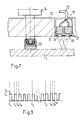
- Fig. 7 einen Ausschnitt zur Darstellung des Abstandselements und des Sensors.
- 1 shows a representation of the scanning scheme according to the invention;
- 2 shows the relationship between the angle and the measured value;
- 3 shows a schematic illustration of the difference value detection according to the invention;
- 4 shows a section through a coin validator according to the invention;
- 5 shows a section along the line AA (see FIG. 4);
- 6 is a plan view of the rear side of the device; and
- Fig. 7 shows a detail showing the spacer and the sensor.
Grundsätzlich sind in den Figuren gleiche Teile mit gleichen Bezugszeichen versehen.In principle, the same parts are provided with the same reference symbols in the figures.
Anhand der Fig. 1 soll das Grundprinzip der Erfindung erläutert werden. Eine Münze 1 wird auf einer konzentrischen Kreisbahn 2 mit vorgegebenem Radius abgetastet. Dabei wird mit einem (später beschriebenen) optischen Sensor eine Reihe IV von Messpunkten 3.1, 3.2 ... 3.N abgetastet. Die Messpunkte haben zueinander exakt definierte relative Winkelpositionen. So sind z.B. die beiden Messpunkte 3.1 und 3.2 um einen exakt bestimmten Winkel a; beabstandet. Die absolute Position eines Messpunkts, d.h. die Position in Relation zum Prägungsbild der Münze auf der Münzoberfläche ist dagegen a priori nicht bekannt. Sie lässt sich aber nachträglich bestimmen, wenn alle Messpunkte 3.1 bis 3.N aufgenommen und ausgewertet worden sind. Der "Phasenfehler" ist nämlich für alle Messpunkte derselbe. Grundsätzlich lässt er sich ohne Probleme berechnen (z.B. mit einem Korrelationsverfahren), in der Praxis ist er aber uninteressant.The basic principle of the invention will be explained with reference to FIG. 1. A
Die Messpunkte 3.1 bis 3.N haben einen vorgegebenen Durchmesser, der vom Sensor bestimmt wird. Typischerweise sind die Messpunkte 3.1 bis 3.N mehr oder weniger kreisförmig und haben einen Durchmesser zwischen 0.1 und 0.3 mm. Vorzugsweise sind die Messpunkte 3.1 bis 3.N so nahe beieinander, dass sie sich zumindest gegenseitig berühren, wenn nicht sogar teilweise überlappen. Die Kreisbahn 2 wird dann vollständig abgedeckt.The measuring points 3.1 to 3.N have a predetermined diameter, which is determined by the sensor. Typically, the measuring points 3.1 to 3.N are more or less circular and have a diameter between 0.1 and 0.3 mm. The measurement points 3.1 to 3.N are preferably so close to one another that they at least touch one another, if not partially overlap. The
Fig. 2 zeigt eine Darstellung der Winkelabhängigkeit der gemessenen Intensitäten. Auf der Abszisse ist der Winkel a aufgetragen und auf der Ordinate die Intensität I. Gemäss der Erfindung können die Messwerte I t (a) einem exakt bestimmten Mittel zugeordnet werden. Das Erkennungsmuster einer Münze besteht daher aus einer Reihe von Wertepaaren (Winkel, Intensität).2 shows a representation of the angle dependence of the measured intensities. The angle a is plotted on the abscissa and the intensity I is plotted on the ordinate. According to the invention, the measured values I t (a) can be assigned to an exactly determined mean. The recognition pattern of a coin therefore consists of a series of pairs of values (angle, intensity).
In der Darstellung der Fig. 2 liesse sich der Unterschied gegenüber dem Stand der Technik dadurch zum Ausdruck bringen, dass bei den bekannten Abtastverfahren auf der Abszisse die Zeit und nicht der Winkel aufgetragen würde. Beim Stand der Technik ist also in der Regel der zeitliche Abstand bekannt, nicht aber der winkelmässige. Dies hat seinen Grund wie bereits erwähnt darin, dass beim Stand der Technik ein unkontrollierbarer Schlupf beim Drehen der Münze vorhanden ist wegen der nicht genau kontrollierbaren Rollbewegung.In the illustration in FIG. 2, the difference compared to the prior art could be expressed in that, in the known scanning methods, the time and not the angle would be plotted on the abscissa. In the prior art, the time interval is generally known, but not the angular one. As already mentioned, this is due to the fact that, in the prior art, there is an uncontrollable slip when rotating the coin because of the rolling movement which cannot be precisely controlled.
Das erfindungsgemässe Verfahren beruht auf einer Reflexionsmessung. Mit einer kleinen Lichtquelle wird der Messpunkt beleuchtet und das unter einem vorgegebenen Winkel reflektierte Licht gemessen. Die Intensität des reflektierten Lichts hängt einerseits von der Krümmung oder Neigung der beleuchteten Oberfläche und andererseits vom Abstand zwischen Sensor und Münzoberfläche ab. Neben diesen beiden durch die Prägung bestimmten Einflüssen spielen natürlich auch die Qualität der Oberfläche und das Mass der Verschmutzung eine Rolle. Für die Erfindung ist es wichtig, dass alle jene Einflüsse eliminiert werden können, die nicht durch die Prägung selbst bedingt sind. Dazu gehören z.B. Fehler in der Strahlengeometrie oder Streulichteinflüsse. Geometrische Fehler können durch eine bzgl. des Münzmittelpunktes rotationsinvariante Strahlengeometrie und durch eine präzise Mechanik unter Kontrolle gehalten werden. Streulichteinflüsse werden vorzugsweise durch eine Differenzlichtmessung, wie sie nachfolgend anhand der Fig. 3 erläutert wird, eliminiert.The method according to the invention is based on a reflection measurement. The measuring point is illuminated with a small light source and the light reflected at a predetermined angle is measured. The intensity of the reflected light depends on the one hand on the curvature or inclination of the illuminated surface and on the other hand on the distance between the sensor and the surface of the coin. In addition to these two influences determined by the embossing, the quality of the surface and the degree of contamination also play a role. It is important for the invention that all those influences that are not caused by the embossing itself can be eliminated. These include e.g. Errors in the beam geometry or effects of scattered light. Geometric errors can be kept under control by means of a radiation geometry that is invariable with respect to the center of the coin and by precise mechanics. Stray light influences are preferably eliminated by a differential light measurement, as will be explained below with reference to FIG. 3.
Fig. 3 zeigt eine zeitliche Darstellung des Steuersignals Si, mit welchem die Lichtquelle angesteuert wird. S1 ist z.B. ein Rechtecksignal mit einer Frequenz von wenigen kHz (z.B. 5 kHz). Zum Zeitpunkt t1 befindet sich die Münze in einer bestimmten Winkelposition. Innerhalb eines bestimmten Zeitintervalls t2-ti ist nun eine Messung durchzuführen. Es wird deshalb in einem ausgewählten Intervall t12-t11, in welchem der Messpunkt von der Lichtquelle beleuchtet wird, der reflektierte Lichtanteil gemessen. Der so ermittelte Messwert beinhaltet Nutzlicht- und Streulichtanteil. Um den Streulichtanteil eliminieren zu können, wird in einem zweiten Intervall gleicher Länge t13-t12 eine Streulichtmessung durchgeführt. Aus den beiden Messwerten wird sodann die Differenz ermittelt. Dies kann bereits im Sensor geschehen, so dass ein streulichtbereinigter Messwert ausgelesen werden kann. Die Differenz kann aber ebenso gut in einer separaten Auswerteschaltung erfolgen.3 shows a time representation of the control signal Si with which the light source is controlled. S 1 is, for example, a square wave signal with a frequency of a few kHz (eg 5 kHz). At time t 1 , the coin is in a certain angular position. A measurement must now be carried out within a certain time interval t 2 -ti. The reflected light component is therefore measured in a selected interval t 12 -t 11 , in which the measuring point is illuminated by the light source. The measured value determined in this way contains the proportion of useful light and scattered light. In order to be able to eliminate the scattered light component, a scattered light measurement is carried out in a second interval of the same length t 13 -t12. The difference is then determined from the two measured values. This can already be done in the sensor, so that a measurement value adjusted for stray light can be read out. The difference can, however, just as well be made in a separate evaluation circuit.
Nachdem die Messung durchgeführt worden ist (t > t2), wird ein neuer Messpunkt angefahren. Danach (t > 13) wird erneut eine Differenzmessung in der vorbeschriebenen Weise durchgeführt (131, t32, t33) usw. Es ist für die Differenzlichtmessung von untergeordneter Bedeutung, ob das Streulicht vor oder nach der eigentlichen Messung aufgenommen wird.After the measurement has been carried out (t> t 2 ), a new measuring point is approached. Then (t> 1 3 ), a differential measurement is carried out again in the manner described above (1 31 , t 32 , t 33 ), etc. It is of secondary importance for the differential light measurement whether the stray light is recorded before or after the actual measurement.
Typischerweise werden entlang der vorgegebenen Kreisbahn wenige hundert (z.B. 200) Messwerte aufgenommen. Um den Einfluss von Verschmutzungen oder Abnützungen der Oberfläche möglichst gering halten zu können, werden die Messwerte vorzugsweise amplitudenmässig normiert. Die Normierung kann auf den Mittelwert, die Varianz oder eine sonstige allgemeine Gewichtung erfolgen.Typically, a few hundred (e.g. 200) measured values are recorded along the specified circular path. In order to keep the influence of dirt or wear on the surface as low as possible, the measured values are preferably standardized in terms of amplitude. The normalization can be based on the mean, the variance or some other general weighting.
An dieser Stelle sei auf einen weiteren Vorteil der punktweisen Abtastung gegenüber der integralen hingewiesen; und zwar sind integrale Messungen amplitudenmässig nicht normierbar. Das heisst, Störeffekte können nicht im selben Mass ausgeglichen werden wie bei der Einzelpunktabtastung.At this point we would like to point out another advantage of point-by-point scanning compared to the integral one; namely, integral measurements cannot be standardized in terms of amplitude. This means that interference effects cannot be compensated to the same extent as with single-point scanning.
Die aufgenommene Messwertreihe wird mit an sich bekannten Verfahren ausgewertet. Sie kann z.B. mit einem abgespeicherten Erkennungsmuster kreuzkorreliert werden. Rechnerisch etwas aufwendiger, aber prinzipiell brauchbar wäre die Durchführung einer Integraltransformation (z.B. FourierTransformation).Weniger rechenintensiv, aber auch weniger differenziert wäre die Berechnung des Schwerpunkts oder die Bestimmung der Minima und Maxima.The recorded series of measured values is evaluated using methods known per se. It can e.g. can be cross-correlated with a stored recognition pattern. Performing an integral transformation (e.g. Fourier transformation) would be somewhat more complex, but would be useful in principle. The calculation of the center of gravity or the determination of the minima and maxima would be less computationally intensive, but also less differentiated.
Im folgenden wird anhand der Fig. 4 bis 7 eine besonders bevorzugte Ausführungsform der Erfindung beschrieben.A particularly preferred embodiment of the invention is described below with reference to FIGS. 4 to 7.
Die Münze 1 ist in einer Halterung 4 fixiert. Führungsbleche 5.1, 5.2 übergreifen die Münze 1 am Rand und verhindern so deren Herausfallen. Die Halterung 4 ist so ausgebildet, dass Münzen mit verschiedenen Durchmessern mit ihrem Mittelpunkt stets auf der gleichen Stelle liegen. Eine solche Münzhalterung ist beispielsweise aus der eingangs zitierten EP 0245805 bekannt. Selbstverständlich sind auch andere Münzhalterungen denkbar. Beispielsweise kann die Münze auch zwischen zwei gegenläufig bewegbaren und mit V-förmigen Ausschnitten versehenen Armen zentriert werden.The
Mit der Halterung 4 ist ein Aufbau verbunden, der im wesentlichen dazu dient, den optischen Sensor entlang der konzentrischen Kreisbahn zu bewegen. Zu diesem Zweck ist eine Trägerplatte 7 vorgesehen, die über Stützelemente 6.1 bis 6.3 mit der Halterung 4 resp. deren Führungsbleche 5.1 und 5.2 verbunden ist. Die Trägerplatte 7 liegt parallel zur Münzoberfläche. Auf der der Halterung 4 abgewandten Seite der Trägerplatte 7 ragen zwei Führungsstangen 8.1 und 8.2 senkrecht nach hinten heraus. Auf diesen beiden Führungsstangen 8.1 und 8.2 wird ein Motorträger 12 geführt. Der Motorträger 12 weist entsprechend ausgebildete Bohrungen mit darin angeordneten Linearkugellagern 10.1 und 10.2 auf. Der Motorträger 12 ist also senkrecht zur Münzoberfläche vor- und zurückbewegbar. Zwischen der Trägerplatte 7 und dem Motorträger 12 sind auf den Führungsstangen 8.1 und 8.2 Spiralfedern 9.1 resp. 9.2 angeordnet. Sie schieben den Motorträger 12 nach hinten, d.h. von der Münze 1 weg. Eine Anschlagplatte 11, die hinter dem Motorträger 12 an den Führungsstangen 8.1 und 8.2 fixiert ist, bietet dem durch die Spiralfedern 9.1 und 9.2 nach hinten geschobenen Motorträger 12 einen Anschlag.A structure is connected to the
Am Motorträger 12 ist ein Schrittmotor 13 befestigt. Seine Achse steht senkrecht zur Münzoberfläche. Die Trägerplatte 7 weist an entsprechender Stelle eine Bohrung für ein Verlängerungsstück 14 auf, welches auf die Achse des Schrittmotors 13 geschraubt ist. Das Verlängerungsstück 14 setzt die Achse bis zur Münzoberfläche fort. An ihm ist ein Sensorträger 15 befestigt, der in einer Ebene parallel zur Münzoberfläche um den Münzmittelpunkt rotierbar ist. Am Sensorträger 15 ist nun der optische Sensor 19 (z.B. ein Lichtschrankenelement) befestigt.A
Zuvorderst am Verlängerungsstück 14 ist ein Abstandselement 16 angebracht. Es befindet sich an der Rotationsachse und definiert den Abstand zwischen Sensor 19 und Oberfläche der Münze 1 während des Abtastens.A
In Fig. 6 sind seitlich die beiden Führungsstangen 8.1 und 8.2 eingezeichnet, auf denen der Motorträger 12 gleitet. In Fig. 6 oben und unten sind zwei Elektromagnete 17.1 und 17.2 vorgesehen. Sie sind also um 90 ° bzgl. der Achse des Schrittmotors 13 gegenüber den Führungsstangen 8.1 und 8.2 versetzt. Sie sind dazu da, den Motorträger 12 und damit den Schrittmotor 13, das Achsverlängerungsstück 14, den Sensorträger 15 und das Abstandselement 16 gegen die Kraft der Spiralfedern 9.1 und 9.2 nach vorne, d.h. gegen die Münze 1, zu ziehen. Es sind deshalb zwei Anker 18.1 und 18.2 vorgesehen, die an der Trägerplatte 7 befestigt sind und von den Elektromagneten 17.1 und 17.2 in sich hineingezogen werden können. Mit anderen Worten: Wenn die beiden Elektromagnete 17.1 und 17.2 mit Strom beaufschlagt werden, dann wird das Abstandselement 16 auf die Hauptfläche der Münze 1 gedrückt. Die Münze 1 wird auf diese Weise zusätzlich fixiert. Zudem wird - wie bereits erwähnt - ein definierter Abstand zwischen Sensor und abzutastender Hauptfläche der Münze 1 geschaffen.In Fig. 6, the two guide rods 8.1 and 8.2 are drawn on the side, on which the
Fig. 7 zeigt eine Detailansicht des Sensorträgers 15 mit dem von ihm festgehaltenen Sensor 19. Der Sensorträger 15 ist z.B. eine Platte, die auf die Achse des Schrittmotors resp. auf das Verlängerungsstück 14 aufgeschraubt wird. Der Sensor 19 selbst ist vorzugsweise ein handelsüblicher Lichtschrankenbaustein. Ein solcher beinhaltet eine Leuchtdiode 21, ein Phototransistor 22 sowie Linsen 24 und 25, die dafür sorgen, dass Leuchtdiode 21 und Phototransistor 22 auf einen gemeinsamen Fokuspunkt ausgerichtet sind. Durch die kleinen Erhebungen der Prägung wird im Prinzip die optimale Reflexion in charakteristischer Weise beeinträchtigt. Es leuchtet ein, dass das Münzsignal verfälscht wird, wenn der Sensor 19 nicht einen konstanten mittleren Abstand von der Münzoberfläche hat. Eine sehr wichtige Massnahme besteht deshalb darin, dass der Sensorträger 15 absolut parallel zur Münze 1 bewegt wird. Eine zweite bevorzugte Massnahme besteht darin, dass auf der Rotationsachse eine Kunststoffkuppe 20 befestigt ist, die durch die Kraft der Elektromagneten 17.1 und 17.2 auf die abgetastete Hauptfläche der Münze 1 gedrückt wird.Fig. 7 shows a detailed view of the
Bei der Erfindung wird mit ein und demselben Sensor eine Kreisbahn vollständig abgetastet. Das heisst, der Sensorträger 15 muss um mindestens 360 rotiert werden. Dabei muss in jeder Winkelstellung garantiert sein, dass der Sensor 19 mit einem Steuersignal (S1) angesteuert und die entsprechenden Messwerte aufgenommen werden können. Gemäss der Erfindung wird ein Anschlusskabel 23 mit den zu- und wegführenden Drähten um die Achse resp. das Verlängerungsstück 14 in mehreren losen Umdrehungen herumgeführt. Auf diese Weise wird freie Kabellänge geschaffen, die während des Abtastens (d.h. während der Rotation) aufgenommen resp. abgegeben werden kann. Die Biegesteifigkeit des Kabelmaterials hält das Anschlusskabel 23 spiralförmig beabstandet vom Verlängerungsstück 14. Das Kabel wird sich daher nicht verklemmen oder verhaspeln.In the invention, a circular path is completely scanned with one and the same sensor. This means that the
Die Erfindung beschränkt sich nicht auf das beschriebene Ausführungsbeispiel. Im folgenden werden Ausführungsvarianten angedeutet, die dies zum Ausdruck bringen sollen.The invention is not limited to the exemplary embodiment described. In the following, design variants are indicated which are intended to express this.
Gleichmässig beabstandete Messpunkte sind zwar vorteilhaft, aber nicht zwingend. Bei Bedarf ist es nämlich ohne weiteres möglich, Zwischenwerte durch Interpolation zu ermitteln. Wichtig ist natürlich, dass die Abstände der Messpunkte so gewählt sind, dass keine relevanten Stellen im Prägungsmuster der abzutastenden Münze übersprungen werden können.Evenly spaced measuring points are advantageous, but not mandatory. If necessary, it is easily possible to determine interim values by interpolation. It is of course important that the distances between the measuring points are chosen so that no relevant points in the coinage pattern of the coin to be scanned can be skipped.
Zwar wird in der Regel das Rotieren der Halterung der Münze nicht vorteilhaft sein. Gleiches gilt aber nicht für die axiale Verschiebung des Sensors gegenüber der Münze gemäss der beschriebenen vorteilhaften Ausführungsform. Eine solche Verschiebung lässt sich konstruktiv ohne übermässigen Aufwand bewerkstelligen. Es ist deshalb ebenso gut möglich, die Halterung vor- und zurückzubewegen.As a rule, rotating the holder of the coin will not be advantageous. The same does not apply to the axial displacement of the sensor relative to the coin according to the advantageous embodiment described. Such a shift can be accomplished constructively without undue effort. It is therefore equally possible to move the holder back and forth.
Bei den in den EP 0245805-A2 beschriebenen Münzautomaten werden die geprüften Münzen vom Automaten sortiert. Ein Wägelchen fährt zwischen den Oeffnungsschlitzen verschiedener Münzsammelbehälter hin und her und lässt die Münze an geeigneter Stelle fallen. Bei einer solchen Ausführungsform kann z.B. die lineare Bewegung des Wägelchens, auf welchem ein in geeigneter Weise rotierbarer Sensor montiert ist, unter Verwendung eines Zahnstangengetriebes in eine rotative Bewegung umgesetzt werden. Ein auf dem Wägelchen selbst angeordneter Schrittmotor zum Rotieren des Sensors kann dann entfallen resp. durch ein Zahnstangen-/Zahnradgetriebe ersetzt werden.In the coin machines described in EP 0245805-A2, the checked coins are sorted by the machine. A trolley moves back and forth between the opening slots of various coin collecting containers and drops the coin at a suitable point. In such an embodiment e.g. the linear movement of the trolley, on which a suitably rotatable sensor is mounted, can be converted into a rotary movement using a rack and pinion gear. A stepper motor arranged on the carriage itself for rotating the sensor can then be omitted or. be replaced by a rack and pinion gear.
Der lineare Vorschub des Sensors zwecks Einstellung der gewünschten Arbeitsdistanz (Abstandselement) kann auch mit anderen Mitteln als mit Elektromagneten bewirkt werden. Insbesondere kann z.B. ein Linearmotor oder Schrittmotor eingesetzt werden. Wenn ein exakt definierter Abstand ohne das bevorzugte Abstandselement verwirklicht werden kann, dann kann auf den linearen Vorschub insgesamt verzichtet werden.The linear advance of the sensor for the purpose of setting the desired working distance (spacer element) can also be effected by means other than electromagnets. In particular, e.g. a linear motor or stepper motor can be used. If a precisely defined distance can be achieved without the preferred distance element, then the linear feed can be dispensed with altogether.
Auch die konstruktiven Einzelheiten sind nicht unerlässlich für den Erfolg der Erfindung. Abwandlungen ergeben sich für den Fachmann aus der Gesamtheit der Beschreibung. Vorzugsweise arbeitet die Erfindung mit einem Sensor pro Kreisbahn. Zur Verbesserung der Messwertreihe können auch zwei oder mehr Sensoren gleichzeitig "rotiert" werden.The structural details are not essential for the success of the invention. For a person skilled in the art, modifications result from the entirety of the description. The invention preferably works with one sensor per circular path. To improve the series of measured values, two or more sensors can also be "rotated" at the same time.
Anstelle eines Lichtschrankenelements kann auch eine Anordnung mit einer Lichtquelle und mehrerer, unter unterschiedlichen Winkeln gleichzeitig messenden Photodetektoren vorgesehen sein. Die Münze kann insbesondere auch ganzflächig beleuchtet und lokal abgetastet werden. Es können auch mehrere Sensoren auf der gleichen Kreisbahn abtasten, wobei die einzelnen Sensoren um gleiche Winkel gegeneinander versetzt sind (z.B. 4 Sensoren um 90 versetzt). Zum Erfassen einer ganzen Kreisbahn genügt eine relative Rotation zwischen Münze und Sensoranordnung um einen Bruchteil von 360 (z.B. um 900). Ein einzelner Sensor tastet dann nur einen Sektor der Kreisbahn ab.Instead of a light barrier element, an arrangement with a light source and a plurality of photodetectors measuring simultaneously at different angles can also be provided. In particular, the coin can also be illuminated over the whole area and scanned locally. Several sensors can also be scanned on the same circular path, the individual sensors being offset by the same angle (e.g. 4 sensors offset by 90). A relative rotation between coin and sensor arrangement by a fraction of 360 (e.g. by 900) is sufficient to detect an entire circular path. A single sensor then scans only one sector of the circular path.
Die Erfindung zeichnet sich aus durch eine hochauflösende Prägungserkennung. Die Vorrichtung vereinigt hohe Präzision und räumliche Kompaktheit in sich. Unkontrollierte Freiheitsgrade und daher Fehlerquellen sind weitgehend eliminiert.The invention is characterized by high-resolution embossing recognition. The device combines high precision and spatial compactness. Uncontrolled degrees of freedom and therefore sources of error are largely eliminated.
Claims (11)
Applications Claiming Priority (2)
| Application Number | Priority Date | Filing Date | Title |
|---|---|---|---|
| CH362991A CH683463A5 (en) | 1991-12-10 | 1991-12-10 | A method of testing a coin. |
| CH3629/91 | 1991-12-10 |
Publications (1)
| Publication Number | Publication Date |
|---|---|
| EP0546341A1 true EP0546341A1 (en) | 1993-06-16 |
Family
ID=4260089
Family Applications (1)
| Application Number | Title | Priority Date | Filing Date |
|---|---|---|---|
| EP92119438A Withdrawn EP0546341A1 (en) | 1991-12-10 | 1992-11-13 | Coin testing method |
Country Status (2)
| Country | Link |
|---|---|
| EP (1) | EP0546341A1 (en) |
| CH (1) | CH683463A5 (en) |
Cited By (5)
| Publication number | Priority date | Publication date | Assignee | Title |
|---|---|---|---|---|
| EP1136957A1 (en) * | 2000-03-16 | 2001-09-26 | Schäfter + Kirchhoff GmbH | Device for optically validating a coin |
| US6417471B1 (en) * | 1999-03-08 | 2002-07-09 | F. Zimmerman Gmbh & Co., Kg | Device for recognizing coins |
| EP2281279A1 (en) * | 2008-04-18 | 2011-02-09 | Coinsecure, Inc. | Apparatus for producing optical signatures from coinage |
| WO2012038670A1 (en) * | 2010-09-23 | 2012-03-29 | Parkeon | Coin-selecting device |
| CN111932764A (en) * | 2020-06-10 | 2020-11-13 | 范小英 | Novel game token and game token verification device |
Citations (8)
| Publication number | Priority date | Publication date | Assignee | Title |
|---|---|---|---|---|
| CH479128A (en) * | 1968-06-07 | 1969-09-30 | Sodeco Compteurs De Geneve | Coin validator |
| CH503337A (en) * | 1969-02-04 | 1971-02-15 | Sodeco Compteurs De Geneve | Coin identification device |
| CH503338A (en) * | 1969-02-04 | 1971-02-15 | Sodeco Compteurs De Geneve | Coin identification device |
| DE2306187A1 (en) * | 1973-02-08 | 1974-08-15 | Josef Mergili | OPTOELECTTONIC COIN VALIDATOR |
| US3921003A (en) | 1973-10-03 | 1975-11-18 | Mars Inc | Apparatus for identifying coins |
| EP0245805A2 (en) | 1986-05-14 | 1987-11-19 | Ascom Autelca Ag | Coin checking apparatus |
| WO1991006072A1 (en) * | 1989-10-17 | 1991-05-02 | Datalab Oy | A method and a means for recognizing a coin |
| GB2248333A (en) * | 1990-07-18 | 1992-04-01 | Act Soft Hardware | Arrangement for testing the physical characteristics of coins |
-
1991
- 1991-12-10 CH CH362991A patent/CH683463A5/en not_active IP Right Cessation
-
1992
- 1992-11-13 EP EP92119438A patent/EP0546341A1/en not_active Withdrawn
Patent Citations (8)
| Publication number | Priority date | Publication date | Assignee | Title |
|---|---|---|---|---|
| CH479128A (en) * | 1968-06-07 | 1969-09-30 | Sodeco Compteurs De Geneve | Coin validator |
| CH503337A (en) * | 1969-02-04 | 1971-02-15 | Sodeco Compteurs De Geneve | Coin identification device |
| CH503338A (en) * | 1969-02-04 | 1971-02-15 | Sodeco Compteurs De Geneve | Coin identification device |
| DE2306187A1 (en) * | 1973-02-08 | 1974-08-15 | Josef Mergili | OPTOELECTTONIC COIN VALIDATOR |
| US3921003A (en) | 1973-10-03 | 1975-11-18 | Mars Inc | Apparatus for identifying coins |
| EP0245805A2 (en) | 1986-05-14 | 1987-11-19 | Ascom Autelca Ag | Coin checking apparatus |
| WO1991006072A1 (en) * | 1989-10-17 | 1991-05-02 | Datalab Oy | A method and a means for recognizing a coin |
| GB2248333A (en) * | 1990-07-18 | 1992-04-01 | Act Soft Hardware | Arrangement for testing the physical characteristics of coins |
Non-Patent Citations (1)
| Title |
|---|
| "Reconnaissance de relief: Les multiples possibilites de ToptoeTectromque", MESURE-REGULATION-AUTOMATISME, February 1981 (1981-02-01), pages 57 - 61 |
Cited By (8)
| Publication number | Priority date | Publication date | Assignee | Title |
|---|---|---|---|---|
| US6417471B1 (en) * | 1999-03-08 | 2002-07-09 | F. Zimmerman Gmbh & Co., Kg | Device for recognizing coins |
| EP1136957A1 (en) * | 2000-03-16 | 2001-09-26 | Schäfter + Kirchhoff GmbH | Device for optically validating a coin |
| EP2281279A1 (en) * | 2008-04-18 | 2011-02-09 | Coinsecure, Inc. | Apparatus for producing optical signatures from coinage |
| EP2281279B1 (en) * | 2008-04-18 | 2015-11-04 | Coinsecure, Inc. | Apparatus for producing optical signatures from coinage |
| WO2012038670A1 (en) * | 2010-09-23 | 2012-03-29 | Parkeon | Coin-selecting device |
| FR2965389A1 (en) * | 2010-09-23 | 2012-03-30 | Parkeon | DEVICE OF SELECTOR OF COINS OF CURRENCY |
| CN111932764A (en) * | 2020-06-10 | 2020-11-13 | 范小英 | Novel game token and game token verification device |
| CN111932764B (en) * | 2020-06-10 | 2022-09-13 | 灵芒科技(杭州)有限公司 | Game token verifying device |
Also Published As
| Publication number | Publication date |
|---|---|
| CH683463A5 (en) | 1994-03-15 |
Similar Documents
| Publication | Publication Date | Title |
|---|---|---|
| DE68902600T2 (en) | CRUMPING MEASUREMENT OF A TRANSPARENT OR TRANSPARENT MATERIAL. | |
| DE3781664T2 (en) | SURFACE INSPECTION. | |
| DE60029878T2 (en) | Method and apparatus for determining particles using the reflection of a multi-scanning beam | |
| DE3822303C2 (en) | ||
| DE2602001C3 (en) | Device for checking a machined surface of a workpiece | |
| EP0740770B1 (en) | Process and device for measuring eccentric rotary components | |
| DE60124647T2 (en) | Device and method for distance measurement | |
| DE1930111C3 (en) | Optical device for measuring the movement of parts moving in relation to one another | |
| DE10237477B4 (en) | Device for measuring surface defects | |
| DE3611536A1 (en) | Device for automatically testing transparent objects, in particular glass bottles | |
| DE2820661C2 (en) | ||
| DE3613209A1 (en) | OPTICAL SURFACE PROFILE MEASURING DEVICE | |
| DE3935424C2 (en) | ||
| DE3800053C2 (en) | ||
| DE10132844A1 (en) | High-precision displacement measuring device and high-precision displacement measuring method using a displacement sensor unit based on the confocal theory | |
| DE19957413A1 (en) | Device for scanning multiple objects optically incorporates a scanning device sliding on a line, an object-recording device with a constant rotational speed while recording data and an exchangeable carousel insert. | |
| EP0546341A1 (en) | Coin testing method | |
| DE69030363T2 (en) | Symbol scanner | |
| DE10319947B4 (en) | Device for measuring the circumferential shape of rotationally symmetrical workpieces | |
| DE3232885A1 (en) | METHOD FOR AUTOMATICALLY INSPECTING SURFACES | |
| DE4017773A1 (en) | MOTION LARGE SENSOR WITH OPTICAL SENSOR | |
| DE4134747A1 (en) | Light measurement arrangement for detecting surface defects - contains laser source, rotating specimen holders, linearly movable sensor unit with two receivers, one being multiple ring detector | |
| EP0600048A1 (en) | Process for measuring relative angles | |
| CH629297A5 (en) | Device for determining the polar coordinates of the offset of an object with respect to an optical reference line | |
| DE3530062A1 (en) | Device for detecting the inclination of a surface of an object |
Legal Events
| Date | Code | Title | Description |
|---|---|---|---|
| PUAI | Public reference made under article 153(3) epc to a published international application that has entered the european phase |
Free format text: ORIGINAL CODE: 0009012 |
|
| AK | Designated contracting states |
Kind code of ref document: A1 Designated state(s): DE FR GB SE |
|
| 17P | Request for examination filed |
Effective date: 19931120 |
|
| GRAG | Despatch of communication of intention to grant |
Free format text: ORIGINAL CODE: EPIDOS AGRA |
|
| 17Q | First examination report despatched |
Effective date: 19950118 |
|
| GRAH | Despatch of communication of intention to grant a patent |
Free format text: ORIGINAL CODE: EPIDOS IGRA |
|
| GRAH | Despatch of communication of intention to grant a patent |
Free format text: ORIGINAL CODE: EPIDOS IGRA |
|
| GRAG | Despatch of communication of intention to grant |
Free format text: ORIGINAL CODE: EPIDOS AGRA |
|
| STAA | Information on the status of an ep patent application or granted ep patent |
Free format text: STATUS: THE APPLICATION IS DEEMED TO BE WITHDRAWN |
|
| 18D | Application deemed to be withdrawn |
Effective date: 19970603 |