EP0545334B1 - Emulgiervorrichtung zum Emulgieren von Dieselkraftstoff und Wasser - Google Patents
Emulgiervorrichtung zum Emulgieren von Dieselkraftstoff und Wasser Download PDFInfo
- Publication number
- EP0545334B1 EP0545334B1 EP92120388A EP92120388A EP0545334B1 EP 0545334 B1 EP0545334 B1 EP 0545334B1 EP 92120388 A EP92120388 A EP 92120388A EP 92120388 A EP92120388 A EP 92120388A EP 0545334 B1 EP0545334 B1 EP 0545334B1
- Authority
- EP
- European Patent Office
- Prior art keywords
- emulsifying device
- housing
- channel
- water
- wall
- Prior art date
- Legal status (The legal status is an assumption and is not a legal conclusion. Google has not performed a legal analysis and makes no representation as to the accuracy of the status listed.)
- Expired - Lifetime
Links
Images


Classifications
-
- F—MECHANICAL ENGINEERING; LIGHTING; HEATING; WEAPONS; BLASTING
- F02—COMBUSTION ENGINES; HOT-GAS OR COMBUSTION-PRODUCT ENGINE PLANTS
- F02M—SUPPLYING COMBUSTION ENGINES IN GENERAL WITH COMBUSTIBLE MIXTURES OR CONSTITUENTS THEREOF
- F02M25/00—Engine-pertinent apparatus for adding non-fuel substances or small quantities of secondary fuel to combustion-air, main fuel or fuel-air mixture
- F02M25/022—Adding fuel and water emulsion, water or steam
- F02M25/0228—Adding fuel and water emulsion
-
- B—PERFORMING OPERATIONS; TRANSPORTING
- B01—PHYSICAL OR CHEMICAL PROCESSES OR APPARATUS IN GENERAL
- B01F—MIXING, e.g. DISSOLVING, EMULSIFYING OR DISPERSING
- B01F25/00—Flow mixers; Mixers for falling materials, e.g. solid particles
- B01F25/10—Mixing by creating a vortex flow, e.g. by tangential introduction of flow components
-
- C—CHEMISTRY; METALLURGY
- C10—PETROLEUM, GAS OR COKE INDUSTRIES; TECHNICAL GASES CONTAINING CARBON MONOXIDE; FUELS; LUBRICANTS; PEAT
- C10L—FUELS NOT OTHERWISE PROVIDED FOR; NATURAL GAS; SYNTHETIC NATURAL GAS OBTAINED BY PROCESSES NOT COVERED BY SUBCLASSES C10G, C10K; LIQUEFIED PETROLEUM GAS; ADDING MATERIALS TO FUELS OR FIRES TO REDUCE SMOKE OR UNDESIRABLE DEPOSITS OR TO FACILITATE SOOT REMOVAL; FIRELIGHTERS
- C10L1/00—Liquid carbonaceous fuels
- C10L1/32—Liquid carbonaceous fuels consisting of coal-oil suspensions or aqueous emulsions or oil emulsions
- C10L1/328—Oil emulsions containing water or any other hydrophilic phase
-
- F—MECHANICAL ENGINEERING; LIGHTING; HEATING; WEAPONS; BLASTING
- F02—COMBUSTION ENGINES; HOT-GAS OR COMBUSTION-PRODUCT ENGINE PLANTS
- F02B—INTERNAL-COMBUSTION PISTON ENGINES; COMBUSTION ENGINES IN GENERAL
- F02B47/00—Methods of operating engines involving adding non-fuel substances or anti-knock agents to combustion air, fuel, or fuel-air mixtures of engines
- F02B47/02—Methods of operating engines involving adding non-fuel substances or anti-knock agents to combustion air, fuel, or fuel-air mixtures of engines the substances being water or steam
-
- F—MECHANICAL ENGINEERING; LIGHTING; HEATING; WEAPONS; BLASTING
- F02—COMBUSTION ENGINES; HOT-GAS OR COMBUSTION-PRODUCT ENGINE PLANTS
- F02M—SUPPLYING COMBUSTION ENGINES IN GENERAL WITH COMBUSTIBLE MIXTURES OR CONSTITUENTS THEREOF
- F02M25/00—Engine-pertinent apparatus for adding non-fuel substances or small quantities of secondary fuel to combustion-air, main fuel or fuel-air mixture
- F02M25/022—Adding fuel and water emulsion, water or steam
- F02M25/0221—Details of the water supply system, e.g. pumps or arrangement of valves
- F02M25/0225—Water atomisers or mixers, e.g. using ultrasonic waves
-
- B—PERFORMING OPERATIONS; TRANSPORTING
- B01—PHYSICAL OR CHEMICAL PROCESSES OR APPARATUS IN GENERAL
- B01F—MIXING, e.g. DISSOLVING, EMULSIFYING OR DISPERSING
- B01F2101/00—Mixing characterised by the nature of the mixed materials or by the application field
- B01F2101/505—Mixing fuel and water or other fluids to obtain liquid fuel emulsions
-
- B—PERFORMING OPERATIONS; TRANSPORTING
- B01—PHYSICAL OR CHEMICAL PROCESSES OR APPARATUS IN GENERAL
- B01F—MIXING, e.g. DISSOLVING, EMULSIFYING OR DISPERSING
- B01F23/00—Mixing according to the phases to be mixed, e.g. dispersing or emulsifying
- B01F23/40—Mixing liquids with liquids; Emulsifying
- B01F23/41—Emulsifying
-
- F—MECHANICAL ENGINEERING; LIGHTING; HEATING; WEAPONS; BLASTING
- F02—COMBUSTION ENGINES; HOT-GAS OR COMBUSTION-PRODUCT ENGINE PLANTS
- F02B—INTERNAL-COMBUSTION PISTON ENGINES; COMBUSTION ENGINES IN GENERAL
- F02B3/00—Engines characterised by air compression and subsequent fuel addition
- F02B3/06—Engines characterised by air compression and subsequent fuel addition with compression ignition
-
- Y—GENERAL TAGGING OF NEW TECHNOLOGICAL DEVELOPMENTS; GENERAL TAGGING OF CROSS-SECTIONAL TECHNOLOGIES SPANNING OVER SEVERAL SECTIONS OF THE IPC; TECHNICAL SUBJECTS COVERED BY FORMER USPC CROSS-REFERENCE ART COLLECTIONS [XRACs] AND DIGESTS
- Y02—TECHNOLOGIES OR APPLICATIONS FOR MITIGATION OR ADAPTATION AGAINST CLIMATE CHANGE
- Y02T—CLIMATE CHANGE MITIGATION TECHNOLOGIES RELATED TO TRANSPORTATION
- Y02T10/00—Road transport of goods or passengers
- Y02T10/10—Internal combustion engine [ICE] based vehicles
- Y02T10/12—Improving ICE efficiencies
Definitions
- the invention relates to an emulsifying device according to the preamble of claim 1.
- a device is known from EP-A-392 545.
- Emulsions of diesel oil and tap water produced with such devices are supplied to the engine of a motor vehicle via already existing injection systems.
- the advantage of such devices lies in their simple structure. Refueling is no more complicated than when injecting non-emulsified diesel fuel.
- the mixing ratio is generally controlled electronically. In this way, emulsions of variable water content can be produced and fed to the engine according to the current load and speed.
- a very important advantage of using diesel fuel-water emulsions is the reduction of nitrogen oxides and soot emissions. There is also the possibility of installing a catalyst due to the reduction in soot.
- the swirling required to prepare the emulsion should take place without the aid of mechanical (rotating) elements; foaming should be avoided; the emulsion should be generated where it is actually needed, ie as close as possible to the area around the injection pump; the amount of emulsion should be adaptable to the consumption of the engine; the emulsion should be rich or lean according to engine performance; for this it is above all necessary to control the water content in a sensitive manner in accordance with the respective operating conditions;
- the construction cost of the device should be kept as low as possible in order to keep the manufacturing costs low.
- the volume of the emulsion produced with known devices is relatively large, which leads to inaccuracies in the metered amount when the load ranges change frequently.
- the required amount of emulsifier has to be generated in stock.
- the invention has for its object to design an emulsifying device according to the preamble of claim 1 such that the mixing of diesel fuel and water is as perfect as possible.
- the droplet size should be reduced, any foaming should be avoided, and any moving fittings should be avoided are and the design and thus the manufacturing costs compared to known devices are reduced.
- the emulsifying device has a housing 1 in detail. This is divided into two sub-housings 1.1, 1.2.
- the housing encloses a mixing chamber with inner wall surfaces 2.
- Housing part 1.1 has a connection bore 3 which receives a water injection nozzle 4.
- a connection 5.1 is provided in the housing part 1.1 for supplying diesel fuel.
- Housing part 1.2 has a threaded bore 7.
- a fitting 8 for discharging the diesel fuel / water mixture is screwed into this.
- a first or a second intermediate space 10.1, 10.2 is located between the inner wall surface 2 of the mixing chamber and the outer surface of each hollow body 9.1, 9.2.
- the first space 10.1 is in a conductive connection with the connections for diesel fuel or for water.
- the second space 10.2 is in connection with the connection 7, 8 for the finished mixture.
- the two vortex chambers are connected to one another by a channel 12.
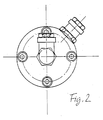
- a connection 5.3 can also be seen in FIG. 1, which is part of a bypass between the first intermediate space 10.1 and the second intermediate space 10.2.
- the first swirl chamber is conductively connected to the first intermediate space 10.1 via bores 14.1 in the wall of the first hollow body 9.1; the second swirl chamber is connected to the second intermediate space 10.2 via bores 14.2 in the wall of the second hollow body 9.2.
- the channel is designed in the manner of a Venturi nozzle; it thus forms a double funnel with a narrow point in the central area of its longitudinal extent.
- the channel 12 is formed from a cylindrical carbon body 15.
- a circular disc 16 is attached to the body 15 in the central region of its longitudinal extent.
- the two parts 15 and 16 are made in one piece with one another and, for example, by casting.
- the two hollow bodies 9.1 and 9.2 have at least approximately the shape of thimbles. They are placed on the cylindrical body 15 from both sides.
- the Connection between the cylindrical body 15 and the two hollow bodies 9.1, 9.2 can be done for example by screwing.
- the disc 16 is clamped between the two housing parts 1.1 and 1.2.
- a plurality of bolts 17 serve for tightening. Otherwise, the disk 16 separates the two spaces 10.1 and 10.2 from one another. Sealing rings 18 ensure reliable sealing.
- FIGS. 3 and 4 Structural details of the hollow bodies 9.1, 9.2 can be seen from FIGS. 3 and 4. These details can be crucial for optimal operation of the emulsifying device. It can be seen, among other things, that the swirl chamber enclosed by the hollow bodies - here hollow bodies 9.1 - has an essentially elliptical shape in this illustration. Seen overall, the vortex chamber has the shape of an ellipsoid of revolution. It can also be seen from FIG. 4 that the bores in the wall of the hollow body 9.1 are inclined against the radial direction. Reference is made to the specified inclination angles. It goes without saying that hollow body 9.2 is designed in the same way, specifically with regard to the shape of the swirl chamber and also with regard to the inclination of the bores.
- the emulsifying device works as follows: the two liquids which are introduced into the connections of housing part 1 first reach the space 10.1. Premixing takes place there. This technologically still imperfect mixture then passes through the bores 14.1 into the first swirl chamber. Another, much more thorough emulsification takes place there.
- the principle of the invention thus exploits a rapid change between tensioning and relaxing.
- the entire system includes all other components normally used, namely a water pump, a water pressure regulator, a water filter, a water tank, as well as a diesel fuel pump, a diesel fuel pressure regulator, a diesel filter and a diesel tank.
- the entire system is controlled with the usual electronics. However, this is not the subject of the invention.
Description
- Die Erfindung betrifft eine Emulgiervorrichtung gemäß dem Oberbegriff von Anspruch 1. Eine solche Vorrichtung ist aus EP-A-392 545 bekannt.
- Mit solchen Vorrichtungen hergestellte Emulsionen aus Dieselöl und Leitungswasser werden dem Motor eines Kraftfahrzeuges über bereits vorhandene Einspritzanlagen zugeführt. Der Vorteil solcher Vorrichtungen liegt in deren einfachem Aufbau. Das Tanken ist nicht komplizierter als bei Einspritzen von nicht-emulgiertem Dieselkraftstoff. Das Mischungsverhältnis wird im allgemeinen elektronisch geregelt. Hierdurch lassen sich Emulsionen variablen Wassergehaltes herstellen und entsprechend der momentanen Belastung und Drehzahl dem Motor zuführen.
- Ein ganz entscheidender Vorteil der Verwendung von Dieselkraftstoff-Wasser-Emulsionen liegt in der Verringerung der Stickoxide sowie der Rußemissionen. Außerdem besteht aufgrund der Rußverringerung die Möglichkeit des Einbaus eines Katalysators.
- Ganz allgemein sind an Emulgiervorrichtungen der eingangs genannten Art die folgenden Anforderungen zu stellen:
die zum Herstellen der Emulsion erforderliche Verwirbelung sollte ohne Zuhilfenahme mechanischer (rotierender) Elemente vonstatten gehen;
eine Schaumbildung sollte vermieden werden;
die Emulsion sollte dort erzeugt werden, wo sie tatsächlich benötigt wird, d.h. möglichst unmittelbar im Bereich der Einspritzpumpe;
die Menge der Emulsion sollte dem Verbrauch des Motors anpaßbar sein;
die Emulsion sollte entsprechend der Motorleistung fett oder mager sein; hierzu ist es vor allem erforderlich, den Wassergehalt entsprechend den jeweiligen Betriebsbedingungen in feinfühliger Weise zu steuern;
der bauliche Aufwand der Vorrichtung sollte möglichst gering gehalten werden, um die Herstellungskosten klein zu halten. - Diese Anforderungen werden von bekannten Emulgiervorrichtungen nur ungenügend erfüllt. Insbesondere haben die bekannten Geräte zum Erzeugen der Verwirbelung rotierende Teile in der Wirbelkammer. Deshalb läßt sich eine Schaumbildung nicht vermeiden. Diese ist jedoch besonders nachteilig, weil hierdurch der Flammpunkt erhöht und damit die Selbstzündung verzögert wird.
- Außerdem ist das Volumen der mit bekannten Vorrichtungen erzeugten Emulsion relativ groß, was bei häufigem Wechsel der Lastbereiche zu Ungenauigkeiten der dosierten Menge führt. Schließlich muß die benötigte Menge an Emulgat auf Vorrat erzeugt werden.
- Der Erfindung liegt die Aufgabe zugrunde, eine Emulgiervorrichtung gemäß dem Oberbegriff von Anspruch 1 derart zu gestalten, daß die Vermischung von Dieselkraftstoff und Wasser so perfekt wie möglich wird. Insbesondere soll die Tropfengröße verringert werden, jegliche Schaumbildung unterbleiben, jegliche sich bewegende Einbauten vermieden werden und der konstruktive Aufbau und damit auch die Herstellungskosten gegenüber bekannten Vorrichtungen verringert werden.
- Diese Aufgabe wird durch die kennzeichnenden Merkmale von Anspruch 1 gelöst.
- Die Erfindung ist anhand der Zeichnung näher erläutert. Darin ist im einzelnen folgendes dargestellt:
- Fig. 1 zeigt eine Emulgiervorrichtung in einer Schnittansicht.
- Fig. 2 zeigt eine Draufsicht auf die linksseitige Stirnseite der Vorrichtung.
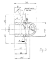
- Fig. 3 zeigt in vergrößertem Maßstab den rechten der beiden Hohlkörper, der sich in der Mischkammer der Vorrichtung befindet.
- Fig. 4 zeigt eine Ansicht gemäß der Schnittlinie A-A in Fig. 3.
- Die Emulgiervorrichtung weist im einzelnen ein Gehäuse 1 auf. Dieses ist in zwei Teilgehäuse 1.1, 1.2 unterteilt. Das Gehäuse umschließt eine Mischkammer mit inneren Wandflächen 2. Gehäuseteil 1.1 weist eine Anschlußbohrung 3 auf, die eine Wassereinspritzdüse 4 aufnimmt. Außerdem ist im Gehäuseteil 1.1 ein Anschluß 5.1 zum Zuführen von Dieselkraftstoff vorgesehen. Gehäuseteil 1.2 weist eine Gewindebohrung 7 auf. In diese ist ein Fitting 8 zum Abführen von Dieselkraftstoff-Wasser-Gemisch eingeschraubt. Man erkennt ferner einen Anschluß 5.2 für den Rücklauf von der hier nicht dargestellten Einspritzpumpe.
- Gemäß der Erfindung sind innerhalb der Mischkammer zwei Hohlkörper 9.1, 9.2 angeordnet, die jeweils eine Wirbelkammer bilden. Zwischen der inneren Wandfläche 2 der Mischkammer und der Außenfläche eines jeden Hohlkörpers 9.1, 9.2 befindet sich ein erster bzw. ein zweiter Zwischenraum 10.1, 10.2. Der erste Zwischenraum 10.1 steht mit den Anschlüssen für Dieselkraftstoff bzw. für Wasser in leitender Verbindung. Der zweite Zwischenraum 10.2 steht mit dem Anschluß 7, 8 für das fertige Gemisch in leitender Verbindung. Die beiden Wirbelkammern sind durch einen Kanal 12 miteinander verbunden. Man erkennt ferner aus Figur 1 einen Anschluß 5.3, der Bestandteil eines Bypass zwischen dem ersten Zwischenraum 10.1 und dem zweiten Zwischenraum 10.2 ist.
- Die erste Wirbelkammer ist über Bohrungen 14.1 in der Wand des ersten Hohlkörpers 9.1 mit dem ersten Zwischenraum 10.1 leitend verbunden; die zweite Wirbelkammer ist über Bohrungen 14.2 in der Wand des zweiten Hohlkörpers 9.2 mit dem zweiten Zwischenraum 10.2 verbunden.
- Wie man weiterhin sieht, ist der Kanal nach Art einer Venturidüse ausgebildet; er bildet somit einen Doppeltrichter mit einer Engstelle im mittleren Bereich seiner Längserstreckung. Dabei ist der Kanal 12 aus einem zylindrischen Kohlkörper 15 gebildet. Im mittleren Bereich seiner Längserstreckung ist eine kreisförmige Scheibe 16 an den Körper 15 angesetzt. Die beiden Teile 15 und 16 sind einteilig miteinander und beispielsweise durch Gießen hergestellt.
- Die beiden Hohlkörper 9.1 und 9.2 haben wenigstens annähernd die Form von Fingerhüten. Sie sind von beiden Seiten her auf den zylindrischen Körper 15 aufgesetzt. Die Verbindung zwischen dem zylindrischen Körper 15 und den beiden Hohlkörpern 9.1, 9.2 kann beispielsweise durch Aufschrauben geschehen.
- Die Scheibe 16 ist zwischen den beiden Gehäuseteilen 1.1 und 1.2 eingespannt. Eine Mehrzahl von Bolzenschrauben 17 dient dem Festspannen. Im übrigen trennt die Scheibe 16 die beiden Zwischenräume 10.1 und 10.2 voneinander. Dichtungsringe 18 sorgen für zuverlässige Abdichtung.
- Aus den Figuren 3 und 4 erkennt man bauliche Einzelheiten der Hohlkörper 9.1, 9.2. Diese Einzelheiten können entscheidend sein für ein optimales Arbeiten der Emulgiervorrichtung. So erkennt man unter anderem, daß die von den Hohlkörpern - hier Hohlkörper 9.1 - umschlossene Wirbelkammer in dieser Darstellung eine im wesentlichen elliptische Gestalt hat. Insgesamt gesehen hat die Wirbelkammer die Gestalt eines Rotationsellipsoids. Ferner erkennt man aus Figur 4, daß die Bohrungen in der Wand des Hohlkörpers 9.1 gegen die Radialrichtung geneigt sind. Auf die angegebenen Neigungswinkel wird verwiesen. Es versteht sich, daß Hohlkörper 9.2 in gleicher Weise gestaltet ist, und zwar bezüglich der Form der Wirbelkammer als auch bezüglich der Neigung der Bohrungen.
- Die Emulgiervorrichtung arbeitet wie folgt: die beiden Flüssigkeiten, die in die Anschlüsse von Gehäuseteil 1 eingeführt werden, gelangen zunächst in den Zwischenraum 10.1. Dort findet eine Vorvermischung statt. Dieses technologisch noch unvollkommene Gemisch gelangt sodann durch die Bohrungen 14.1 in die erste Wirbelkammer. Dort findet eine weitere, wesentlich gründlichere Emulgierung statt.
- Bei der Strömung durch Kanal 12 wird dieses Gemisch etwa auf der Mitte der Kanallänge einem relativ geringen Druck ausgesetzt, und sodann wieder am Ausgang des Kanals 12 einem höheren Druck. Das Gemisch gelangt sodann in die zweite Wirbelkammer, die aus Hohlkörper 9.2 gebildet ist. Auch hier findet eine weitere Vermischung bei gleichzeitiger Verkleinerung der Tropfen der beteiligten Komponenten statt. Schließlich tritt das Gemisch aus der zweiten Wirbelkammer durch die Bohrungen 14.2 aus, gelangt in den zweiten Zwischenraum 10.2 und von dort zu Fitting 8, von wo aus es einem Motor (nicht dargestellt) zugeführt wird.
- Das Prinzip der Erfindung nutzt somit einen rapiden Wechsel zwischen Spannen und Entspannen aus.
- Es versteht sich, daß die gesamte Anlage alle übrigen, normalerweise verwendeten Bauteile umfaßt, nämlich eine Wasserpumpe, einen Wasser-Druckregler, einen Wasserfilter, einen Wassertank, desgleichen eine Dieselkraftstoff-Pumpe, einen Dieselkraftstoff-Druckregler, einen Dieselfilter sowie einen Dieseltank. Die gesamte Anlage ist mit der üblichen Elektronik gesteuert. Dies ist jedoch nicht Gegenstand der Erfindung.
Claims (11)
- Emulgiervorrichtung zum Emulgieren von Dieselkraftstoff und Wasser mit den folgenden Merkmalen:1.1 ein Gehäuse (1), das eine Mischkammer mit einer inneren Wandfläche (2) enthält;1.2 einen Anschluß (3) am Gehäuse (1) für eine Wassereinspritzdüse (4);1.3 einen Anschluß am Gehäuse zum Zuführen von Dieselkraftstoff;1.4 einen Anschluß (7, 8) am Gehäuse (1) zum Abführen von Gemisch aus Dieselkraftstoff und Wasser; gekennzeichnet durch die folgenden Merkmale:1.5 innerhalb der Mischkammer sind zwei Hohlkörper (9.1, 9.2) angeordnet, die jeweils eine Wirbelkammer bilden;1.6 zwischen der inneren Wandfläche (2) der Mischkammer und der Außenfläche eines jeden Hohlkörpers (9.1, 9.2) befindet sich ein erster bzw. ein zweiter Zwischenraum (10.1, 10.2);1.7 der erste Zwischenraum (10.1) steht mit Anschlüssen für Dieselkraftstoff bzw. Wasser in leitender Verbindung, der zweite Zwischenraum (10.2) steht mit dem Anschluß für das Gemisch in leitender Verbindung;1.8 die beiden Wirbelkammern sind durch einen Kanal (12) miteinander verbunden;1.9 die erste Wirbelkammer ist über wenigstens eine Bohrung (14.1) in der Wand des ersten Hohlkörpers (9.1) mit dem ersten Zwischenraum (10.1) verbunden, und die zweite Wirbelkammer ist über wenigstens eine Bohrung (14.2) in der Wand des zweiten Hohlkörpers (9.2) mit dem zweiten Zwischenraum (10.2) verbunden.
- Emulgiervorrichtung nach Anspruch 1, dadurch gekennzeichnet, daß der Kanal (12) nach Art einer Venturidüse ausgebildet ist (Doppeltrichter).
- Emulgiervorrichtung nach Anspruch 1 oder 2, dadurch gekennzeichnet, daß die beiden Zwischenräume (10.1, 10.2) durch eine scheibenförmige Wand (Ringwand 16) voneinander getrennt sind.
- Emulgiervorrichtung nach einem der Ansprüche 1-3, dadurch gekennzeichnet, daß die Mischkammer und die beiden Hohlkörper (9.1, 9.2) in Bezug auf eine zur Strömungsrichtung im Kanal (12) senkrechte Ebene, die den Kanal (12) in zwei gleiche Längsabschnitte unterteilt, symmetrisch angeordnet und gestaltet sind.
- Emulgiervorrichtung nach einem der Ansprüche 1-4, dadurch gekennzeichnet, daß die beiden Hohlkörper (9.1, 9.2) jeweils im wesentlichen die Form eines Fingerhutes haben.
- Emulgiervorrichtung nach Anspruch 5, dadurch gekennzeichnet, daß der Kanal (12) aus einem zylindrischen Körper (15) gebildet ist, und daß die beiden Hohlkörper (9.1, 9.2) von beiden Seiten her auf den zylindrischen Körper (15) aufgeschoben sind.
- Emulgiervorrichtung nach Anspruch 3 und 6, sowie nach einem der Ansprüche 4 oder 5, dadurch gekennzeichnet, daß der zylindrische Körper (15) die Ringwand (16) trägt, bzw. mit dieser einteilig verbunden ist.
- Emulgiervorrichtung nach einem der Ansprüche 3-7, dadurch gekennzeichnet, daß das Gehäuse (1) in zwei Teilgehäuse (1.1, 1.2) unterteilt und die Ringwand (16) zwischen diesen beiden Teilgehäusen eingespannt ist.
- Emulgiervorrichtung nach einem der Ansprüche 1-8, dadurch gekennzeichnet, daß die Wirbelkammern - in einem in Strömungsrichtung durch den Kanal (12) gelegten Schnitt - eine elliptische Gestalt haben.
- Emulgiervorrichtung nach einem der Ansprüche 1-9, dadurch gekennzeichnet, daß am Gehäuse ein Anschluß (5.2) vorgesehen ist, zum Anschluß einer Rücklaufleitung zwischen einer Einspritzpumpe und dem ersten Zwischenraum (10.1).
- Emulgiervorrichtung nach einem der Ansprüche 1-10, dadurch gekennzeichnet, daß die beiden Zwischenräume (10.1 und 10.2) über eine Bypassleitung miteinander verbindbar sind.
Applications Claiming Priority (2)
| Application Number | Priority Date | Filing Date | Title |
|---|---|---|---|
| DE4139782A DE4139782C2 (de) | 1991-12-03 | 1991-12-03 | Emulgiervorrichtung zum Emulgieren von Dieselkraftstoff und Wasser |
| DE4139782 | 1991-12-03 |
Publications (3)
| Publication Number | Publication Date |
|---|---|
| EP0545334A2 EP0545334A2 (de) | 1993-06-09 |
| EP0545334A3 EP0545334A3 (en) | 1993-07-07 |
| EP0545334B1 true EP0545334B1 (de) | 1995-02-01 |
Family
ID=6446134
Family Applications (1)
| Application Number | Title | Priority Date | Filing Date |
|---|---|---|---|
| EP92120388A Expired - Lifetime EP0545334B1 (de) | 1991-12-03 | 1992-11-28 | Emulgiervorrichtung zum Emulgieren von Dieselkraftstoff und Wasser |
Country Status (4)
| Country | Link |
|---|---|
| EP (1) | EP0545334B1 (de) |
| JP (1) | JPH0712327A (de) |
| AT (1) | ATE118068T1 (de) |
| DE (2) | DE4139782C2 (de) |
Cited By (2)
| Publication number | Priority date | Publication date | Assignee | Title |
|---|---|---|---|---|
| DE19819271A1 (de) * | 1998-04-30 | 1999-11-11 | Guenther Kramb | Dosiervorrichtung für eine Emulgieranlage |
| DE102012104053B3 (de) * | 2012-05-09 | 2013-09-26 | Karlsruher Institut für Technologie | Emulgiervorrichtung |
Families Citing this family (9)
| Publication number | Priority date | Publication date | Assignee | Title |
|---|---|---|---|---|
| DE4241603C1 (de) * | 1992-12-10 | 1994-04-07 | Mtu Friedrichshafen Gmbh | Einrichtung zum Herstellen eines Gemisches von flüssigem Brennstoff und Zusatzflüssigkeit |
| DE19820707C1 (de) * | 1998-05-11 | 2000-02-17 | Guenther Kramb | Emulgiervorrichtung |
| CN1116102C (zh) * | 2000-03-06 | 2003-07-30 | 姜志福 | 定向楔乳化剂制造机 |
| JP3563354B2 (ja) | 2001-02-09 | 2004-09-08 | 株式会社椿本チエイン | ころ軸受を組み込んだローラチェーン |
| JP4640017B2 (ja) * | 2005-07-29 | 2011-03-02 | 株式会社日立プラントテクノロジー | 乳化装置 |
| JP4852968B2 (ja) * | 2005-10-24 | 2012-01-11 | 株式会社日立プラントテクノロジー | 乳化方法とその装置 |
| DE102010022414A1 (de) | 2010-06-01 | 2011-12-01 | Günther Kramb jun. | Emulgiervorrichtung |
| DE102017213705A1 (de) | 2017-08-07 | 2019-02-07 | Jan Kramb | Verfahren und Vorrichtung zum Reduzieren der Emissionen eines Verbrennungsmotors |
| WO2021148673A1 (de) | 2020-01-23 | 2021-07-29 | Raptech Eberswalde Gmbh | Anlage und verfahren zur herstellung einer stabilen kohlenwasserstoff-wasser-dispersion für die verbesserung der verbrennungsprozesse und einer leicht in mindestens zwei phasen trennbaren wasser-kohlenwasserstoff-dispersion im rahmen des reinigungsverfahrens von havarieorten |
Family Cites Families (4)
| Publication number | Priority date | Publication date | Assignee | Title |
|---|---|---|---|---|
| FR1514272A (fr) * | 1967-01-06 | 1968-02-23 | Commissariat Energie Atomique | Dispositif de circulation |
| FI61814C (fi) * | 1980-07-22 | 1982-10-11 | Finnreg Oy | Emulgeringsanordning |
| US4594969A (en) * | 1981-09-29 | 1986-06-17 | Aleksander Przybylski | Method and apparatus for producing a fuel mixture |
| DE3912344A1 (de) * | 1989-04-14 | 1990-10-18 | Harrier Gmbh | Einrichtung zum herstellen einer oel-wasser-emulsion |
-
1991
- 1991-12-03 DE DE4139782A patent/DE4139782C2/de not_active Expired - Fee Related
-
1992
- 1992-11-28 AT AT92120388T patent/ATE118068T1/de not_active IP Right Cessation
- 1992-11-28 DE DE59201338T patent/DE59201338D1/de not_active Expired - Fee Related
- 1992-11-28 EP EP92120388A patent/EP0545334B1/de not_active Expired - Lifetime
- 1992-12-03 JP JP4324505A patent/JPH0712327A/ja active Pending
Cited By (4)
| Publication number | Priority date | Publication date | Assignee | Title |
|---|---|---|---|---|
| DE19819271A1 (de) * | 1998-04-30 | 1999-11-11 | Guenther Kramb | Dosiervorrichtung für eine Emulgieranlage |
| DE102012104053B3 (de) * | 2012-05-09 | 2013-09-26 | Karlsruher Institut für Technologie | Emulgiervorrichtung |
| EP2662131A2 (de) | 2012-05-09 | 2013-11-13 | Karlsruher Institut für Technologie | Emulgiervorrichtung |
| EP2662131A3 (de) * | 2012-05-09 | 2014-09-03 | Karlsruher Institut für Technologie | Emulgiervorrichtung |
Also Published As
| Publication number | Publication date |
|---|---|
| DE4139782C2 (de) | 1994-05-19 |
| EP0545334A2 (de) | 1993-06-09 |
| DE4139782A1 (de) | 1993-06-09 |
| DE59201338D1 (de) | 1995-03-16 |
| EP0545334A3 (en) | 1993-07-07 |
| ATE118068T1 (de) | 1995-02-15 |
| JPH0712327A (ja) | 1995-01-17 |
Similar Documents
| Publication | Publication Date | Title |
|---|---|---|
| DE3217674C2 (de) | Brennkammer für eine Gasturbine | |
| DE10044624B4 (de) | Koaxial-Einspritzdüse | |
| DE2730791C2 (de) | Brennkammer für Gasturbinentriebwerke | |
| DE2213124A1 (de) | Vorrichtung zum Einspritzen von Kraftstoff in Brennkraftmaschinen | |
| EP0545334B1 (de) | Emulgiervorrichtung zum Emulgieren von Dieselkraftstoff und Wasser | |
| DE2655901A1 (de) | Verfahren und vorrichtung zum mischen von fluessigkeiten | |
| DE3139309A1 (de) | Brennkraftmaschine | |
| DE19650559C1 (de) | Anschlußelement zum Einleiten von Brennstoff und einem zweiten Fluid in ein Einspritzventil | |
| DE3517406A1 (de) | Intermittierende dralleinspritzduese | |
| DE10111221A1 (de) | Kraftstoffeinspritzsystem | |
| DE2844504A1 (de) | Brennstoffzufuehrungsvorrichtung fuer einen verbrennungsmotor | |
| DE2907223A1 (de) | Kraftstoffansaugsystem fuer verbrennungsmaschinen mit mehreren zylindern | |
| DE3244854A1 (de) | Brenner | |
| DE10393644T5 (de) | Kraftstoffeinspritzdüsenpassstück | |
| DE3025528C2 (de) | Vergaser mit veränderlicher Venturidüse | |
| EP0204687B1 (de) | Zweitakt-Brennkraftmaschine | |
| DE2746521A1 (de) | Kraftstoffzerstaeubungsvorrichtung | |
| DE3040952C2 (de) | Ansaugsystem für eine Brennkraftmaschine | |
| DE19820707C1 (de) | Emulgiervorrichtung | |
| DE3237798C2 (de) | Dieselmotor mit einem Hauptbrennraum und einer Wirbelkammer | |
| DE3642654C2 (de) | Treibstoffeinspritzsystem für Staustrahltriebwerke | |
| EP0083001A1 (de) | Kraftstoffeinspritzsystem für Kraftstoffdirekteinspritzung bei Brennkraftmaschinen | |
| EP0674941B1 (de) | Vorrichtung zur Bildung einer Öl-Wasser-Emulsion | |
| EP0814254B1 (de) | Verfahren und Vorrichtung zum Beimischen von Zusatz-stoffen in eine Fluid-strömung | |
| DE2500097A1 (de) | Zerstaeubungsduese fuer fluessigkeit, insbesondere fuer fluessige kraft- oder brennstoffe |
Legal Events
| Date | Code | Title | Description |
|---|---|---|---|
| PUAI | Public reference made under article 153(3) epc to a published international application that has entered the european phase |
Free format text: ORIGINAL CODE: 0009012 |
|
| PUAL | Search report despatched |
Free format text: ORIGINAL CODE: 0009013 |
|
| AK | Designated contracting states |
Kind code of ref document: A2 Designated state(s): AT BE CH DE DK ES FR GB GR IT LI LU NL PT SE |
|
| AK | Designated contracting states |
Kind code of ref document: A3 Designated state(s): AT BE CH DE DK ES FR GB GR IT LI LU NL PT SE |
|
| 17P | Request for examination filed |
Effective date: 19930820 |
|
| 17Q | First examination report despatched |
Effective date: 19940110 |
|
| GRAA | (expected) grant |
Free format text: ORIGINAL CODE: 0009210 |
|
| AK | Designated contracting states |
Kind code of ref document: B1 Designated state(s): AT BE CH DE DK ES FR GB GR IT LI LU NL PT SE |
|
| PG25 | Lapsed in a contracting state [announced via postgrant information from national office to epo] |
Ref country code: GR Free format text: LAPSE BECAUSE OF FAILURE TO SUBMIT A TRANSLATION OF THE DESCRIPTION OR TO PAY THE FEE WITHIN THE PRESCRIBED TIME-LIMIT Effective date: 19950201 Ref country code: GB Effective date: 19950201 Ref country code: ES Free format text: THE PATENT HAS BEEN ANNULLED BY A DECISION OF A NATIONAL AUTHORITY Effective date: 19950201 Ref country code: DK Effective date: 19950201 Ref country code: BE Effective date: 19950201 |
|
| REF | Corresponds to: |
Ref document number: 118068 Country of ref document: AT Date of ref document: 19950215 Kind code of ref document: T |
|
| REF | Corresponds to: |
Ref document number: 59201338 Country of ref document: DE Date of ref document: 19950316 |
|
| ITF | It: translation for a ep patent filed |
Owner name: STUDIO TORTA SOCIETA' SEMPLICE |
|
| PG25 | Lapsed in a contracting state [announced via postgrant information from national office to epo] |
Ref country code: PT Effective date: 19950502 |
|
| ET | Fr: translation filed | ||
| GBV | Gb: ep patent (uk) treated as always having been void in accordance with gb section 77(7)/1977 [no translation filed] |
Effective date: 19950201 |
|
| PG25 | Lapsed in a contracting state [announced via postgrant information from national office to epo] |
Ref country code: AT Effective date: 19951128 |
|
| PG25 | Lapsed in a contracting state [announced via postgrant information from national office to epo] |
Ref country code: LU Free format text: LAPSE BECAUSE OF NON-PAYMENT OF DUE FEES Effective date: 19951130 |
|
| PLBE | No opposition filed within time limit |
Free format text: ORIGINAL CODE: 0009261 |
|
| STAA | Information on the status of an ep patent application or granted ep patent |
Free format text: STATUS: NO OPPOSITION FILED WITHIN TIME LIMIT |
|
| 26N | No opposition filed | ||
| REG | Reference to a national code |
Ref country code: CH Ref legal event code: PL |
|
| REG | Reference to a national code |
Ref country code: CH Ref legal event code: AEN Free format text: DAS PATENT IST AUFGRUND DES WEITERBEHANDLUNGSANTRAGS VOM 10.09.1996 REAKTIVIERT WORDEN. |
|
| NLS | Nl: assignments of ep-patents |
Owner name: GUENTHER KRAMB;JAN KRAMB |
|
| REG | Reference to a national code |
Ref country code: FR Ref legal event code: TP |
|
| PGFP | Annual fee paid to national office [announced via postgrant information from national office to epo] |
Ref country code: SE Payment date: 19981120 Year of fee payment: 7 |
|
| PGFP | Annual fee paid to national office [announced via postgrant information from national office to epo] |
Ref country code: NL Payment date: 19981126 Year of fee payment: 7 |
|
| PG25 | Lapsed in a contracting state [announced via postgrant information from national office to epo] |
Ref country code: SE Free format text: LAPSE BECAUSE OF NON-PAYMENT OF DUE FEES Effective date: 19991129 |
|
| PG25 | Lapsed in a contracting state [announced via postgrant information from national office to epo] |
Ref country code: NL Free format text: LAPSE BECAUSE OF NON-PAYMENT OF DUE FEES Effective date: 20000601 |
|
| EUG | Se: european patent has lapsed |
Ref document number: 92120388.1 |
|
| NLV4 | Nl: lapsed or anulled due to non-payment of the annual fee |
Effective date: 20000601 |
|
| PGFP | Annual fee paid to national office [announced via postgrant information from national office to epo] |
Ref country code: FR Payment date: 20001124 Year of fee payment: 9 |
|
| PGFP | Annual fee paid to national office [announced via postgrant information from national office to epo] |
Ref country code: DE Payment date: 20020619 Year of fee payment: 10 |
|
| PG25 | Lapsed in a contracting state [announced via postgrant information from national office to epo] |
Ref country code: FR Free format text: LAPSE BECAUSE OF NON-PAYMENT OF DUE FEES Effective date: 20020730 |
|
| REG | Reference to a national code |
Ref country code: FR Ref legal event code: ST |
|
| REG | Reference to a national code |
Ref country code: FR Ref legal event code: ST |
|
| PG25 | Lapsed in a contracting state [announced via postgrant information from national office to epo] |
Ref country code: DE Free format text: LAPSE BECAUSE OF NON-PAYMENT OF DUE FEES Effective date: 20030603 |
|
| PGFP | Annual fee paid to national office [announced via postgrant information from national office to epo] |
Ref country code: CH Payment date: 20050506 Year of fee payment: 13 |
|
| PG25 | Lapsed in a contracting state [announced via postgrant information from national office to epo] |
Ref country code: IT Free format text: LAPSE BECAUSE OF NON-PAYMENT OF DUE FEES Effective date: 20051128 |
|
| PG25 | Lapsed in a contracting state [announced via postgrant information from national office to epo] |
Ref country code: LI Free format text: LAPSE BECAUSE OF NON-PAYMENT OF DUE FEES Effective date: 20051130 Ref country code: CH Free format text: LAPSE BECAUSE OF NON-PAYMENT OF DUE FEES Effective date: 20051130 |
|
| REG | Reference to a national code |
Ref country code: CH Ref legal event code: PL |