EP0545281A1 - Brenner zur Herstellung von Synthesegas - Google Patents
Brenner zur Herstellung von Synthesegas Download PDFInfo
- Publication number
- EP0545281A1 EP0545281A1 EP92120171A EP92120171A EP0545281A1 EP 0545281 A1 EP0545281 A1 EP 0545281A1 EP 92120171 A EP92120171 A EP 92120171A EP 92120171 A EP92120171 A EP 92120171A EP 0545281 A1 EP0545281 A1 EP 0545281A1
- Authority
- EP
- European Patent Office
- Prior art keywords
- burner
- burner according
- individual
- ceramic
- individual ceramic
- Prior art date
- Legal status (The legal status is an assumption and is not a legal conclusion. Google has not performed a legal analysis and makes no representation as to the accuracy of the status listed.)
- Granted
Links
Images

Classifications
-
- C—CHEMISTRY; METALLURGY
- C01—INORGANIC CHEMISTRY
- C01B—NON-METALLIC ELEMENTS; COMPOUNDS THEREOF; METALLOIDS OR COMPOUNDS THEREOF NOT COVERED BY SUBCLASS C01C
- C01B3/00—Hydrogen; Gaseous mixtures containing hydrogen; Separation of hydrogen from mixtures containing it; Purification of hydrogen
- C01B3/02—Production of hydrogen or of gaseous mixtures containing a substantial proportion of hydrogen
- C01B3/32—Production of hydrogen or of gaseous mixtures containing a substantial proportion of hydrogen by reaction of gaseous or liquid organic compounds with gasifying agents, e.g. water, carbon dioxide, air
- C01B3/34—Production of hydrogen or of gaseous mixtures containing a substantial proportion of hydrogen by reaction of gaseous or liquid organic compounds with gasifying agents, e.g. water, carbon dioxide, air by reaction of hydrocarbons with gasifying agents
- C01B3/36—Production of hydrogen or of gaseous mixtures containing a substantial proportion of hydrogen by reaction of gaseous or liquid organic compounds with gasifying agents, e.g. water, carbon dioxide, air by reaction of hydrocarbons with gasifying agents using oxygen or mixtures containing oxygen as gasifying agents
- C01B3/363—Production of hydrogen or of gaseous mixtures containing a substantial proportion of hydrogen by reaction of gaseous or liquid organic compounds with gasifying agents, e.g. water, carbon dioxide, air by reaction of hydrocarbons with gasifying agents using oxygen or mixtures containing oxygen as gasifying agents characterised by the burner used
-
- C—CHEMISTRY; METALLURGY
- C10—PETROLEUM, GAS OR COKE INDUSTRIES; TECHNICAL GASES CONTAINING CARBON MONOXIDE; FUELS; LUBRICANTS; PEAT
- C10J—PRODUCTION OF PRODUCER GAS, WATER-GAS, SYNTHESIS GAS FROM SOLID CARBONACEOUS MATERIAL, OR MIXTURES CONTAINING THESE GASES; CARBURETTING AIR OR OTHER GASES
- C10J3/00—Production of combustible gases containing carbon monoxide from solid carbonaceous fuels
- C10J3/46—Gasification of granular or pulverulent flues in suspension
- C10J3/48—Apparatus; Plants
- C10J3/50—Fuel charging devices
- C10J3/506—Fuel charging devices for entrained flow gasifiers
-
- F—MECHANICAL ENGINEERING; LIGHTING; HEATING; WEAPONS; BLASTING
- F23—COMBUSTION APPARATUS; COMBUSTION PROCESSES
- F23D—BURNERS
- F23D1/00—Burners for combustion of pulverulent fuel
- F23D1/005—Burners for combustion of pulverulent fuel burning a mixture of pulverulent fuel delivered as a slurry, i.e. comprising a carrying liquid
-
- C—CHEMISTRY; METALLURGY
- C10—PETROLEUM, GAS OR COKE INDUSTRIES; TECHNICAL GASES CONTAINING CARBON MONOXIDE; FUELS; LUBRICANTS; PEAT
- C10J—PRODUCTION OF PRODUCER GAS, WATER-GAS, SYNTHESIS GAS FROM SOLID CARBONACEOUS MATERIAL, OR MIXTURES CONTAINING THESE GASES; CARBURETTING AIR OR OTHER GASES
- C10J2300/00—Details of gasification processes
- C10J2300/12—Heating the gasifier
- C10J2300/1223—Heating the gasifier by burners
-
- F—MECHANICAL ENGINEERING; LIGHTING; HEATING; WEAPONS; BLASTING
- F23—COMBUSTION APPARATUS; COMBUSTION PROCESSES
- F23D—BURNERS
- F23D2212/00—Burner material specifications
-
- F—MECHANICAL ENGINEERING; LIGHTING; HEATING; WEAPONS; BLASTING
- F23—COMBUSTION APPARATUS; COMBUSTION PROCESSES
- F23D—BURNERS
- F23D2214/00—Cooling
-
- F—MECHANICAL ENGINEERING; LIGHTING; HEATING; WEAPONS; BLASTING
- F23—COMBUSTION APPARATUS; COMBUSTION PROCESSES
- F23D—BURNERS
- F23D2900/00—Special features of, or arrangements for burners using fluid fuels or solid fuels suspended in a carrier gas
- F23D2900/00018—Means for protecting parts of the burner, e.g. ceramic lining outside of the flame tube
-
- Y—GENERAL TAGGING OF NEW TECHNOLOGICAL DEVELOPMENTS; GENERAL TAGGING OF CROSS-SECTIONAL TECHNOLOGIES SPANNING OVER SEVERAL SECTIONS OF THE IPC; TECHNICAL SUBJECTS COVERED BY FORMER USPC CROSS-REFERENCE ART COLLECTIONS [XRACs] AND DIGESTS
- Y10—TECHNICAL SUBJECTS COVERED BY FORMER USPC
- Y10S—TECHNICAL SUBJECTS COVERED BY FORMER USPC CROSS-REFERENCE ART COLLECTIONS [XRACs] AND DIGESTS
- Y10S239/00—Fluid sprinkling, spraying, and diffusing
- Y10S239/19—Nozzle materials
Definitions
- the present invention relates to a burner for producing synthesis gas by partial oxidation of carbon-containing fuels with improved properties.
- Synthesis gas is usually produced by partial oxidation of carbon-containing material with oxygen or an oxygen-containing gas, for example air under elevated pressure and comparatively high temperatures of 1000 to 1600 ° C.
- oxygen or an oxygen-containing gas for example air under elevated pressure and comparatively high temperatures of 1000 to 1600 ° C.
- the carbonaceous material hydrocarbons, slurries of solid carbonaceous fuels in hydrocarbons, or slurries of solid carbonaceous fuels in water such as coal-water suspensions are used.
- EP 0 095 103 B1 describes a method and a burner for the production of synthesis gas.
- the process is carried out with the aid of a burner system consisting of three concentrically arranged tubes, three streams of material being fed to the reaction.
- the material stream containing oxygen or the oxygen-containing gas is passed through the inner and the outer zone of the burner and the carbon-containing material, namely a coal-water suspension, is passed through the annular space formed by the inner and middle tube.
- the inner material flow accounts for 1 to 20% of the total amount of oxygen required for the partial oxidation, the remaining oxygen requirement is covered by the outer material flow, which enters the reaction through the annular space formed by the middle and outer tube.
- the burner has three concentrically arranged tubes, each of which has a conically tapering end, and a cooling chamber in the region of the burner outlet.
- the coal-water suspension forming the middle material flow is fed to the reactor, which is under a pressure of 1 to 20 MPa, at a speed of 1 to 25, in particular 2 to 15, m / sec, while the inner and the outer gas flow are fed at a speed from 50 to 300, in particular 80 to 200 m / sec reach the reaction zone.
- the conical tapering of the concentrically arranged tubes causes the three material flows to meet at an acute angle. It is thereby achieved that the coal-water suspension stream is pressed apart or torn apart by the inner gas stream after leaving the end of the conical taper. The suspension flow is therefore subject to horizontal deflection and does not pass the reaction zone in free fall. As a result, the average residence time of the individual coal-water droplets increases and the degree of implementation is increased.
- the outer gas stream meets the stream of the coal-water suspension expanded by the inner gas stream and achieves further mixing of gas and suspension, so that a zone of uniform distribution of gas or oxygen and the finest suspension droplets is formed. This is an essential prerequisite for implementing the coal-water suspension as much as possible.
- the partial oxidation of the carbonaceous fuel leads to a chemically very aggressive mixture which contains about 30 to 50% by weight of carbon monoxide, about 30 to 50% by weight of hydrogen, about 3 to 20% by weight of CO2 and contains unreacted water vapor and, in smaller quantities, contains sulfur, iron, vanadium, nickel, sodium chlorine and calcium in addition to other substances.
- the material composition and the ash content of the gasification product formed depend on the one hand on the type of fuel and on the other hand on the process conditions, such as the amount of oxygen, the set temperature and the pressure.
- the partial oxidation of hydrocarbon-containing fuels is usually carried out at about 1000 to 1600, in particular at 1200 to 1600 ° C. and pressures of 1.0 to 15.0, in particular 2.0 to 10, preferably 3.0 to 5.0 MPa.
- the hydrogen contained in the synthesis gas results from the conversion of water, which is fed to the partial oxidation in the liquid state and / or in the form of water vapor.
- the water required for the reaction can be used as a separate stream or in a mixture with other streams, for example mixed with the hydrocarbon, the oxygen or the gas stream containing oxygen. It is also possible to distribute the water over several material flows both in the liquid state and in vapor form.
- the burner Due to the composition of the very reactive gas mixture resulting from the partial oxidation, in connection with the high temperatures, the burner is also exposed to a high degree of chemical attack.
- slag particles which are deposited on the burner in a molten state, for example, lead to a load on the burner due to chemical reactions and erosion, in particular in the region of the end face of the burner.
- the burner is particularly exposed to thermal stress, which is caused by the high intensity of the heat radiation occurring during gasification.
- This thermal load is higher in the gasification of hydrocarbon-containing fuels than in the corresponding implementation of a coal-water suspension.
- the higher gasification temperature and on the other hand the shorter one Distance of the burner to the gasification zone.
- the higher temperature is a consequence of the easier combustibility of the hydrocarbon and the reduced distance results from earlier ignition of the hydrocarbon, due to its considerably lower ignition temperature compared to a coal-water suspension.
- the burner In continuous operation, the burner is not only exposed to vibrations and a chemical attack by the highly reactive synthesis gas, but also to erosion due to slag particles and a high thermal load.
- high-quality materials in particular high-alloy stainless steels such as Incoloy and Hastelloy, are used for the part of the burner protruding into the gasification reactor, the burner has a very limited life expectancy of around three to four months. This is of considerable disadvantage for the operation of a modern plant for the production of synthesis gas, since the burner can only be replaced when the plant is switched off. Switching off the synthesis gas system, however, entails cooling and relaxing the apparatus under pressure. After replacing the defective burner with a new one, the system must first be reheated and pressurized before the synthesis gas can be restarted.
- a burner for the production of synthesis gas by partial oxidation of carbon-containing fuels containing three or more tubes which are arranged concentrically to one another and which, if appropriate have a conical taper at the burner outlet and a cooling chamber surrounding the burner outlet and arranged in the end face of the burner. It is characterized in that the end face facing the zone of partial oxidation is clad with a layer composed of individual ceramic plates arranged next to one another.
- the burner according to the invention contains at least three, in particular three to six, preferably three to four, particularly preferably three tubes arranged concentrically to one another.
- the conical tapering possibly present at the burner outlet of the tubes arranged concentrically to one another form the outlet openings for the individual material flows, the innermost tube forming a circular outlet opening and the other tubes arranged concentrically to one another forming corresponding annular outlet openings.
- the burner according to the invention is suitable for the partial oxidation of both coal-water suspensions and hydrocarbons or fuels containing hydrocarbons. It has proven itself particularly in the production of synthesis gas by partial oxidation of hydrocarbons or fuels containing hydrocarbons.
- the end of the burner facing the gasification zone is clad with individual ceramic plates, which are arranged side by side, covering the entire area, in the manner of a mosaic.
- the individual ceramic plates are connected to each other and to the front of the burner by means of a ceramic adhesive.
- the ceramic adhesive forms a layer on the front of the burner in which the individual ceramic plates are embedded.
- the individual ceramic plate has one or more bulges and the front side of the burner has corresponding indentations for receiving the bulges.
- the ceramic plates of the individual rings are expediently arranged offset from one another. This avoids the formation of long, continuous joints, which could have a negative impact on the mechanical stability of the cladding.
- the individual ceramic plates can have any shape. They can be round, square, rectangular, diamond-shaped, triangular, quadrangular or have the shape of a regular or irregular polygon. Ceramic plates of the same or different shape can be arranged side by side.
- Ceramic plates that have the shape of a trapezoid or a ring segment are particularly suitable. This shape facilitates the arrangement of the individual ceramic plates in a ring.
- the individual ceramic plate should have a layer thickness of 1 to 10, in particular 2 to 5 mm, calculated in each case without the bulge serving as anchoring in the end face of the burner.
- the sides of the individual ceramic plates should not be chosen too long.
- the length of the individual pages up to 50 mm should be sufficient. In most cases it is advisable to use ceramic plates that have a length of 5 to 35, in particular 6 to 30, preferably 8 to 20 mm on each side.
- the individual ceramic plate consists of a ceramic that is resistant to the conditions that occur in the gasification reaction.
- Suitable materials are oxide ceramics which contain, for example, Al2O3, Cr2O3, MgO ZrO2 and / or SiO2, or non-oxide ceramics which include, for example, carbides and nitrides of boron, aluminum or silicon. Silicon nitride is particularly suitable.
- the ceramic adhesive must also be resistant to the conditions occurring in the gasification reaction and ensure a permanent, elastic connection between the individual ceramic plates and the end face of the burner.
- a ceramic adhesive based on an aluminum silicate which is adapted to the thermal expansion behavior of the ceramic plates, has proven particularly useful.
- FIG. 1 shows a longitudinal section through the lower part of the burner according to the invention facing the zone of gasification.
- the burner consists of an outer double jacket tube 1, which has a conical taper 1a and an inserted tube 2 for supplying a coolant, and a plurality of inner tubes 3, 4 and 5 which are arranged concentrically to one another and have corresponding conical tapering 3a, 4a and 5a.
- the individual material flows pass through the gaps, firstly from the double-walled tube 1 and the inner tube 3, secondly from the inner tube 3 and the inner tube 4 and thirdly from the inner tube 4 and that arranged in the middle of the burner Tube 5 are formed.
- Another stream of material is passed through tube 5.
- the material flows emerge at the end of the ring openings formed by the conical tapering 1a, 3a, 4a and 5a and through the conical tapering 5a of the tube 5.
- the double jacket tube 1 is closed at the end of its conical taper 1a. This closed part forms the end face 6 of the burner, which is covered with a layer 7 composed of individual ceramic plates arranged next to one another.
- the coolant preferably water, is introduced through the tube 2 inserted into the double-jacket tube 1.
- the double jacket tube 1 acts as a cooling chamber, in particular in the region of its conical taper 1a.
- Figure 1a shows a detail of the burner in longitudinal section, shown enlarged.
- 1a stands for the conical taper of the double jacket tube 1, which together with the Tube 2 carrying coolant forms a cooling chamber, and 6 for the end face clad with ceramic plates 7a having a dovetail-shaped bulge.
- the ceramic plates are connected to one another and to the end face 6 of the burner by means of a layer 8 of a ceramic adhesive.
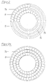
- FIG. 2 shows the end face 6 of the burner, partially covered with ceramic plates 7a, in supervision. To simplify the illustration, the inner tubes 3, 4 and 5 are not shown.
- the annular end face 6 has three dovetail-shaped ring grooves 7b for receiving the dovetail-shaped bulges of the ceramic plates 7a.
- Each annular groove 7b has an enlarged opening 7c, which serves to insert the dovetail-shaped bulge in the ceramic plates 7a.
- a corresponding ring is formed by lining up the individual ceramic plates.
- the dovetail-shaped bulge of the ceramic plate to be inserted last is first inserted into the enlarged opening 7c, after which the entire ring formed from the individual ceramic plates is shifted by half the length of the enlarged opening 7c. In this way it is ensured that the two ceramic plates adjacent to the enlarged opening 7c are at least partially with their dovetail-shaped bulge 7a in the annular groove 7b.
- FIG. 2a shows a top view of the end face 6 of the burner, which is completely covered with individual ceramic plates 7a arranged next to one another.
- the ceramic plates 7a have the shape of a trapezoid and are strung together in such a way that they result in three concentrically arranged ring surfaces.
- the joint filled with layer 8 of the ceramic adhesive is located between the individual ceramic plates.
- the inner tubes 3, 4 and 5 are not shown in order to simplify the illustration.
Landscapes
- Chemical & Material Sciences (AREA)
- Engineering & Computer Science (AREA)
- Combustion & Propulsion (AREA)
- Organic Chemistry (AREA)
- Chemical Kinetics & Catalysis (AREA)
- Inorganic Chemistry (AREA)
- Health & Medical Sciences (AREA)
- General Health & Medical Sciences (AREA)
- General Engineering & Computer Science (AREA)
- Mechanical Engineering (AREA)
- Oil, Petroleum & Natural Gas (AREA)
- Gas Burners (AREA)
- Pre-Mixing And Non-Premixing Gas Burner (AREA)
- Hydrogen, Water And Hydrids (AREA)
- Manufacture, Treatment Of Glass Fibers (AREA)
- Physical Or Chemical Processes And Apparatus (AREA)
Abstract
Description
- Die vorliegende Erfindung betrifft einen Brenner zur Herstellung von Synthesegas durch partielle Oxidation kohlenstoffhaltiger Brennstoffe mit verbesserten Eigenschaften.
- Die Herstellung von Synthesegas erfolgt üblicherweise durch partielle Oxidation kohlenstoffhaltigen Materials mit Sauerstoff oder einem Sauerstoff enthaltenden Gas, beispielsweise Luft unter erhöhtem Druck und vergleichsweise hohen Temperaturen von 1000 bis 1600°C. Als kohlenstoffhaltiges Material werden Kohlenwasserstoffe, Aufschlämmungen von festen kohlenstoffhaltigen Brennstoffen in Kohlenwasserstoffen oder Aufschlämmungen fester kohlenstoffhaltiger Brennstoffe in Wasser wie Kohle-Wasser-Suspensionen verwendet.
- Die EP 0 095 103 B1 beschreibt ein Verfahren und einen Brenner zur Herstellung von Synthesegas. Das Verfahren wird mit Hilfe eines aus drei konzentrisch angeordneten Rohren bestehenden Brennersystems, wobei drei Stoffströme der Umsetzung zugeleitet werden, durchgeführt. Der Sauerstoff oder der sauerstoffhaltiges Gas enthaltende Stoffstrom wird durch die innere und die äußere Zone des Brenners geführt und das kohlenstoffhaltige Material, nämlich eine Kohle-Wasser-Suspension, durch den aus dem inneren und mittlerem Rohr gebildeten Ringraum geleitet. Auf den inneren Stoffstrom entfallen 1 bis 20 % der insgesamt für die partielle Oxidation erforderlichen Sauerstoffmenge, der verbleibende Sauerstoffbedarf wird durch den äußeren Stoffstrom, der durch den aus dem mittleren und äußeren Rohr gebildeten Ringraum in die Reaktion gelangt, gedeckt.
- Der Brenner weist drei konzentrisch angeordnete Rohre, die jeweils ein sich konisch verjüngendes Ende besitzen, sowie eine Kühlkammer im Bereich des Brennerausganges auf.
- Die den mittleren Stoffstrom bildende Kohle-Wasser-Suspension wird dem unter einem Druck von 1 bis 20 MPa stehenden Reaktor mit einer Geschwindigkeit von 1 bis 25, insbesondere 2 bis 15 m/sec zugeführt, während der innere wie auch der äußere Gasstrom mit einer Geschwindigkeit von 50 bis 300, insbesondere 80 bis 200 m/sec in die Reaktionszone gelangen.
- Durch die konische Verjüngungen der konzentrisch angeordneten Rohre wird bewirkt, daß die drei Stoffströme unter einem spitzen Winkel aufeinandertreffen. Dadurch wird erreicht, daß der Kohle-Wasser-Suspensionsstrom nach Verlassen des Endes der konischen Verjüngung durch den inneren Gasstrom auseinandergedrückt bzw. aufgerissen wird. Somit unterliegt der Suspensionsstrom einer horizontalen Ablenkung und passiert die Reaktionszone nicht im freien Fall. Demzufolge vergrößert sich die mittlere Aufenthaltszeit der einzelnen Kohle-Wasser-Tröpfchen und der Umsetzungsgrad wird gesteigert.
- Gleichzeitig trifft der äußere Gasstrom auf den durch den inneren Gasstrom aufgeweiteten Strom der Kohle-Wasser-Suspension und erzielt eine weitere Vermischung von Gas und Suspension, so daß eine Zone gleichmäßiger Verteilung von Gas bzw. Sauerstoff und feinsten Suspensionströpfchen entsteht. Dies ist eine wesentliche Voraussetzung, die Kohle-Wasser-Suspension in möglichst hohem Maße umzusetzen.
- Es hat sich herausgestellt, daß für den Einsatz von Kohlenwasserstoff enthaltenden Brennstoffen ähnliche Bedingungen, wie zuvor im Zusammenhang mit Kohle-Wasser-Suspensionen näher beschrieben, von Vorteil sind.
- Die partielle Oxidation des kohlenstoffhaltigen Brennstoffes, insbesondere eines Kohlenwasserstoffs, führt zu einem chemisch sehr aggressiven Gemisch, das etwa 30 bis 50 Gew.-% Kohlenmonoxid, etwa 30 bis 50 Gew.-% Wasserstoff, etwa 3 bis 20 Gew.-% CO₂ und nichtumgesetzten Wasserdampf enthält und in kleineren Mengen neben anderen Stoffen noch Schwefel, Eisen, Vanadium, Nickel, Natrium Chlor und Calcium aufweist.
- Die stoffliche Zusammensetzung und die Ascheanteile des entstehenden Vergasungsproduktes sind einerseits von der Art des Brennstoffs, andererseits von den Verfahrensbedingungen, wie der Sauerstoffmenge, der eingestellten Temperatur und dem Druck abhängig. Üblicherweise wird die partielle Oxidation kohlenwasserstoffhaltiger Brennstoffe bei etwa 1000 bis 1600, insbesondere bei 1200 bis 1600°C und Drücken von 1,0 bis 15,0, insbesondere 2,0 bis 10, bevorzugt 3.0 bis 5.0 MPa durchgeführt. Der im Synthesegas enthaltene Wasserstoff resultiert aus der Umsetzung von Wasser, das der partiellen Oxidation in flüssigem Zustand und/oder in Form von Wasserdampf zugeführt wird. Das für die Umsetzung benötigte Wasser kann als ein separater Stoffstrom oder im Gemisch mit anderen Stoffströmen, beispielsweise mit dem Kohlenwasserstoff, dem Sauerstoff oder dem Sauerstoff enthaltenden Gasstrom vermischt zum Einsatz gelangen. Es ist auch möglich, das Wasser sowohl im flüssigen Zustand als auch in Dampfform auf mehrere Stoffströme zu verteilen.
- Gleiches trifft auch für die Zufuhr des Kohlenwasserstoff enthaltenden Brennstoffs und des Sauerstoff oder ein sauerstoffhaltiges Gasgemisch enthaltenden Stoffstromes zu. Auch diese Stoffströme können entweder als separater Strom oder verteilt auf mehrere Ströme der Umsetzung zugeführt werden.
- Als Folge der in der partiellen Oxidation herrschenden Bedingungen ist der Brenner in erheblichem Maße einer Reihe von physikalischen und chemischen Belastungen ausgesetzt.
- Aufgrund der hohen Austrittsgeschwindigkeit der Stoffströme, insbesondere der Gasströme, treten Vibrationen auf, die eine starke mechanische Beanspruchung des Brenners nach sich ziehen.
- Bedingt durch die Zusammensetzung des aus der partiellen Oxidation resultierenden sehr reaktiven Gasgemisches, in Verbindung mit den hohen Temperaturen, ist der Brenner in hohem Maße auch einem chemischen Angriff ausgeliefert. Daneben führen auch Schlackepartikel, die sich beispielsweise in schmelzflüssigem Zustand auf dem Brenner ablagern, durch chemische Reaktionen und Erosion zu einer Belastung des Brenners, insbesondere im Bereich der Stirnseite des Brenners.
- Daneben ist der Brenner in besonderem Maße einer thermischen Beanspruchung ausgesetzt, die durch die hohe Intensität der bei der Vergasung auftretenden Wärmestrahlung hervorgerufen wird. Diese thermische Belastung fällt bei der Vergasung Kohlenwasserstoffe enthaltender Brennstoffe höher als bei der entsprechenden Umsetzung einer Kohle-Wasser-Suspension aus. Hierfür ist zum einen die höhere Vergasungstemperatur und zum anderen der kürzere Abstand des Brenners zu der Zone der Vergasung verantwortlich. Die höhere Temperatur ist eine Folge der leichteren Brennbarkeit des Kohlenwasserstoffes und der verringerte Abstand resultiert aus einem früheren Zünden des Kohlenwasserstoffes, bedingt durch seine im Vergleich zu einer Kohle-Wasser-Suspension erheblich niedrigere Zündtemperatur.
- Der Brenner ist in Dauerbetrieb nicht nur Vibrationen und einem chemischen Angriff des sehr reaktionsfreudigen Synthesegases, sondern auch einer Erosion durch Schlacketeilchen und einer hohen thermischen Belastung ausgesetzt. Obwohl für den in den Vergasungsreaktor hineinragenden Teil des Brenners hochwertige Werkstoffe, insbesondere hochlegierte Edelstähle wie Incoloy und Hastelloy verwendet werden, besitzt der Brenner eine nur sehr begrenzte Lebenserwartung von etwa drei bis vier Monaten. Dies ist für den Betrieb einer modernen Anlage zur Herstellung von Synthesegas von erheblichem Nachteil, da ein Austausch des Brenners nur bei abgeschalteter Anlage vorgenommen werden kann. Ein Abschalten der Synthesegasanlage zieht jedoch ein Abkühlen und Entspannen der unter Druck stehenden Apparate nach sich. Nach Ersatz des defekten Brenners durch einen neuen muß die Anlage zunächst wieder aufgeheizt und unter Druck gesetzt werden, ehe die Produktion von Synthesegas wieder aufgenommen werden kann.
- Es besteht daher die Aufgabe, einen Brenner mit erheblich gesteigerter Lebenserwartung bereitzustellen.
- Gelöst wird diese Aufgabe durch einen Brenner zur Herstellung von Synthesegas durch partielle Oxidation kohlenstoffhaltiger Brennstoffe, enthaltend drei oder mehr zueinander konzentrisch angeordnete Rohre, die gegebenenfalls am Brennerausgang eine konische Verjüngung aufweisen, und eine den Brennerausgang umgebende, in der Stirnseite des Brenners angeordnete Kühlkammer. Er ist dadurch gekennzeichnet, daß die der Zone der partiellen Oxidation zugewandte Stirnseite mit einer aus einzelnen, nebeneinander angeordneten Keramikplättchen zusammengesetzten Schicht verkleidet ist.
- Der erfindungsgemäße Brenner enthält mindestens drei, insbesondere drei bis sechs, bevorzugt drei bis vier, besonders bevorzugt drei zueinander konzentrisch angeordnete Rohre. Die gegebenenfalls am Brennerausgang der konzentrisch zueinander angeordneten Rohre vorhandenen konischen Verjüngungen bilden die Austrittsöffnungen für die einzelnen Stoffströme, wobei das innerste Rohr eine kreisförmige Austrittsöffnung und die übrigen konzentrisch zueinander angeordneten Rohre entsprechende ringförmige Austrittsöffnungen bilden.
- Der erfindungsgemäße Brenner eignet sich für die partielle Oxidation sowohl von Kohle-Wasser-Suspensionen als auch von Kohlenwasserstoffen oder Kohlenwasserstoff enthaltenden Brennstoffen. Er hat sich besonders bei der Herstellung von Synthesegas durch partielle Oxidation von Kohlenwasserstoffen oder Kohlenwasserstoff enthaltenden Brennstoffen bewährt.
- Die der Vergasungszone zugewandte Stirnseite des Brenners ist mit einzelnen Keramikplättchen, die flächendeckend, nach Art eines Mosaiks, nebeneinander angeordnet sind, verkleidet. Die einzelnen Keramikplättchen sind mittels eines Keramikklebers sowohl untereinander als auch mit der Stirnseite des Brenners verbunden. Der Keramikkleber bildet auf der Stirnseite des Brenners eine Schicht, in die die einzelnen Keramikplättchen eingebettet werden. Nach einer besonderen Ausführungsform weist das einzelne Keramikplättchen eine oder mehrere Ausbuchtungen und die Stirnseite des Brenners entsprechende Einbuchtungen zum Aufnehmen der Ausbuchtungen auf. Durch das Einfügen der an der Unterseite der Keramikplättchen befindlichen Ausbuchtungen in die passend geformten Einbuchtungen wird eine zusätzliche Verbindung von Keramikplättchen und Stirnseite geschaffen und zugleich die mechanische Belastbarkeit erhöht. Besonders bewährt hat es sich, die Ausbuchtungen und Einbuchtungen schwalbenschwanzförmig zu gestalten, es sind jedoch auch andere Formen wie Stifte oder Noppen geeignet.
- Es ist möglich, die Keramikplättchen nebeneinander in beliebiger Anordnung auf der Stirnseite des Brenners flächendeckend zu verteilen. Besonders günstig ist es, die einzelnen Keramikplättchen in einer Weise anzuordnen, daß sie jeweils die Form eines Ringes bilden. Mehrere derartiger, einander konzentrisch umgebender Ringe bedecken die Stirnseite des Brenners.
- Zweckmäßigerweise ordnet man die Keramikplättchen der einzelnen Ringe gegeneinander versetzt an. Auf diese Weise vermeidet man die Bildung langer, durchgehender Fugen, die sich auf die mechanische Stabilität der Verkleidung nachteilig auswirken könnten.
- Die einzelnen Keramikplättchen können eine beliebige Form besitzen. Sie können rund, quadratisch, rechteckig, rautenförmig, dreieckig, viereckig sein oder die Form eines regelmäßigen oder unregelmäßigen Vielecks aufweisen. Es können Keramikplättchen gleicher oder unterschiedlicher Form nebeneinander angeordnet werden.
- Besonders geeignet sind Keramikplättchen, die die Form eines Trapezes oder eines Ringsegmentes aufweisen. Diese Formgebung erleichtert die Anordnung der einzelnen Keramikplättchen zu einem Ring.
- Das einzelne Keramikplättchen soll eine Schichtdicke von 1 bis 10, insbesondere 2 bis 5 mm, gerechnet jeweils ohne die als Verankerung in der Stirnseite des Brenners dienende Ausbuchtung, besitzen. Die Seiten des einzelnen Keramikplättchen sollten nicht zu lang gewählt werden. Eine Länge der einzelnen Seiten bis zu 50 mm dürfte ausreichend bemessen sein. In den meisten Fällen empfiehlt es sich, Keramikplättchen zu verwenden, die je Seite eine Länge von 5 bis 35, insbesondere 6 bis 30, bevorzugt 8 bis 20 mm aufweisen.
- Das einzelne Keramikplättchen besteht aus einer gegenüber den in der Vergasungsreaktion auftretenden Bedingungen beständigen Keramik. Geeignete Materialien sind Oxidkeramiken, die beispielsweise Al₂O₃, Cr₂O₃, MgO ZrO₂ und/oder SiO₂ enthalten, oder Nichtoxidkeramiken, die beispielsweise Carbide und Nitride des Bors, Aluminiums oder Siliciums umfassen. Besonders geeignet ist Siliciumnitrid.
- Auch der Keramikkleber muß gegenüber den in der Vergasungsreaktion auftretenden Bedingungen widerstandsfähig sein und eine dauerhafte, elastische Verbindung zwischen den einzelnen Keramikplättchen und der Stirnseite des Brenners gewährleisten.
- Besonders bewährt hat sich ein Keramikkleber auf Basis eines Alumo-Silikates, der dem thermischen Dehnverhalten der Keramikplättchen angepaßt ist.
- Die nachfolgenden Zeichnungen beschreiben die vorliegende Erfindung näher, ohne sie zu beschränken.
- Figur 1 zeigt einen Längsschnitt durch den unteren, der Zone der Vergasung zugewandten Teil des erfindungsgemäßen Brenners. Der Brenner besteht aus einem äußeren Dopppelmantelrohr 1, das eine konische Verjüngung 1a und ein eingesetztes Rohr 2 zur Zufuhr eines Kühlmittels aufweist, und mehreren zueinander konzentrisch angeordneten inneren Rohren 3, 4 und 5, die entsprechende konische Verjüngungen 3a, 4a und 5a besitzen. Die einzelnen Stoffströme gelangen durch die Zwischenräume, die erstens von dem Doppelmantelrohr 1 und dem inneren Rohr 3, zweitens von dem inneren Rohr 3 und dem weiter innen liegenden Rohr 4 und drittens von dem weiter innen liegenden Rohr 4 und dem in der Mitte des Brenners angeordneten Rohr 5 gebildet werden. Ein weiterer Stoffstrom wird durch das Rohr 5 geführt. Die Stoffströme treten am Ende der durch die konischen Verjüngungen 1a, 3a, 4a und 5a gebildeten Ringöffnungen sowie durch die konische Verjüngung 5a des Rohres 5 aus.
- Das Doppelmantelrohr 1 ist am Ende seiner konischen Verjüngung 1a geschlossen. Diese geschlossene Partie bildet die Stirnseite 6 des Brenners, die mit einer aus einzelnen, nebeneinander angeordneten Keramikplättchen zusammengesetzten Schicht 7 verkleidet ist. Durch das in das Doppelmantelrohr 1 eingesetzte Rohr 2 wird das Kühlmittel, vorzugsweise Wasser, eingeleitet. Dadurch fungiert das Doppelmantelrohr 1, insbesondere im Bereich seiner konischen Verjüngung 1a, als Kühlkammer.
- Figur 1a zeigt im Längsschnitt, vergrößert dargestellt, ein Detail des Brenners. Hierin steht 1a für die konische Verjüngung des Doppelmantelrohres 1, die zusammen mit dem Kühlmittel führenden Rohr 2 eine Kühlkammer bildet, und 6 für die mit eine schwalbenschwanzförmige Ausbuchtung besitzenden Keramikplättchen 7a verkleidete Stirnseite. Die Keramik-plättchen sind sowohl untereinander als auch mit der Stirnseite 6 des Brenners mittels einer Schicht 8 eines Keramikklebers verbunden.
- Figur 2 zeigt die teilweise mit Keramikplättchen 7a bedeckte Stirnseite 6 des Brenners in Aufsicht. Zur Vereinfachung der Darstellung sind die inneren Rohre 3, 4 und 5 nicht eingezeichnet.
- Die ringförmige Stirnseite 6 weist drei schwalbenschwanzförmige Ringnuten 7b zur Aufnahme der schwalbenschwanzförmigen Ausbuchtungen der Keramikplättchen 7a auf. Jede Ringnut 7b besitzt eine erweiterte Öffnung 7c, die zum Einsetzen der schwalbenschwanzförmigen Ausbuchtung der Keramikplättchen 7a dient. Durch Verschieben des Keramikplättchens wird dessen schwalbenschwanzförmige Ausbuchtung in die Ringnut 7b eingeführt. Durch Aneinanderreihen der einzelnen Keramikplättchen bildet sich ein entsprechender Ring. Die schwalbenschwanzförmige Ausbuchtung des zuletzt einzufügenden Keramikplättchens wird zunächst in die erweiterte Öffnung 7c eingesetzt, wobei anschließend der gesamte, aus den einzelnen Keramikplättchen gebildete Ring, um die halbe Länge der erweiterten Öffnung 7c verschoben wird. Auf diese Weise wird sichergestellt, daß sich die beiden, zur erweiterten Öffnung 7c benachbarten Keramikplättchen zumindest zu einem Teil mit ihrer schwalbenschwanzförmigen Ausbuchtung 7a in der Ringnut 7b befinden. Zwischen den einzelnen Keramikplättchen befindet sich eine mit der Schicht 8 des Keramikklebers gefüllte Fuge.
- Figur 2a zeigt die vollständig mit einzelnen, nebeneinander angeordneten Keramikplättchen 7a bedeckte Stirnseite 6 des Brenners in Aufsicht.
- Die Keramikplättchen 7a weisen die Form eines Trapezes auf und sind derart aneinandergereiht, daß sie drei konzentrisch angeordnete Ringflächen ergeben. Zwischen den einzelnen Keramikplättchen befindet sich die mit der Schicht 8 des Keramikklebers gefüllte Fuge.
- Wie in Figur 2 sind zur Vereinfachung der Darstellung die inneren Rohre 3, 4 und 5 nicht eingezeichnet.
Claims (10)
- Brenner zur Herstellung von Synthesegas durch partielle Oxidation kohlenstoffhaltiger Brennstoffe, enthaltend drei oder mehr zueinander konzentrisch angeordnete Rohre, die gegebenenfalls am Brennerausgang eine konische Verjüngung aufweisen, und eine den Brennerausgang umgebende, in der Stirnseite des Brenners angeordnete Kühlkammer, dadurch gekennzeichnet, daß die der Zone der partiellen Oxidation zugewandte Stirnseite mit einer aus einzelnen, nebeneinander angeordneten Keramikplättchen zusammengesetzten Schicht verkleidet ist.
- Brenner nach Anspruch 1, dadurch gekennzeichnet, daß die einzelnen Keramikplättchen mittels eines Keramikklebers untereinander und mit der Stirnseite des Brenners verbunden sind.
- Brenner nach Anspruch 1 oder 2, dadurch gekennzeichnet, daß das einzelne Keramikplättchen eine oder mehrere Ausbuchtungen und die Stirnseite des Brenners entsprechende Einbuchtungen zum Aufnehmen der Ausbuchtungen aufweist.
- Brenner nach einem oder mehreren der Ansprüche 1 bis 3, dadurch gekennzeichnet, daß die Ausbuchtung und die entsprechende Einbuchtung schwalbenschwanzförmig ist.
- Brenner nach einem oder mehreren der Ansprüche 1 bis 4, dadurch gekennzeichnet, daß die einzelnen Keramikplättchen nebeneinander, die Form eines Ringes bildend angeordnet werden.
- Brenner nach einem oder mehreren der Ansprüche 1 bis 5, dadurch gekennzeichnet, daß das einzelne Keramikplättchen die Form eines Kreises, eines Trapezes oder eines Ringsegmentes, insbesondere eines Trapezes oder Ringsegmentes, besitzt.
- Brenner nach einem oder mehreren der Ansprüche 1 bis 6, dadurch gekennzeichnet, daß das einzelne Keramikplättchen eine Schichtdicke von 1 bis 10, insbesondere 2 bis 5 mm aufweist.
- Brenner nach einem oder mehreren der Ansprüche 1 bis 7, dadurch gekennzeichnet, daß das einzelne Keramikplättchen je Seite eine Länge von 5 bis 35, insbesondere 6 bis 30, bevorzugt 8 bis 20 mm aufweist.
- Brenner nach einem oder mehreren der Ansprüche 1 bis 8, dadurch gekennzeichnet, daß das einzelne Keramikplättchen aus einer Keramik auf Basis einer Oxidkeramik, die Al₂O₃, Cr₂O₃, MgO, ZrO₂ und/oder SiO₂ enthält, oder auf Basis einer Nichtoxidkeramik, die ein Carbid oder Nitrid des Bors, Aluminiums oder Siliciums enthält, insbesondere aus Siliciumnitrid, besteht.
- Brenner nach einem oder mehreren der Ansprüche 1 bis 9, dadurch gekennzeichnet, daß der Keramikkleber ein hochtemperaturbeständiges Alumo-Silikat enthält.
Applications Claiming Priority (2)
| Application Number | Priority Date | Filing Date | Title |
|---|---|---|---|
| DE4140063 | 1991-12-05 | ||
| DE4140063A DE4140063A1 (de) | 1991-12-05 | 1991-12-05 | Brenner zur herstellung von synthesegas |
Publications (2)
| Publication Number | Publication Date |
|---|---|
| EP0545281A1 true EP0545281A1 (de) | 1993-06-09 |
| EP0545281B1 EP0545281B1 (de) | 1998-06-24 |
Family
ID=6446303
Family Applications (1)
| Application Number | Title | Priority Date | Filing Date |
|---|---|---|---|
| EP92120171A Expired - Lifetime EP0545281B1 (de) | 1991-12-05 | 1992-11-26 | Brenner zur Herstellung von Synthesegas |
Country Status (12)
| Country | Link |
|---|---|
| US (1) | US5273212A (de) |
| EP (1) | EP0545281B1 (de) |
| JP (1) | JPH0670228B2 (de) |
| CN (1) | CN1036932C (de) |
| AT (1) | ATE167697T1 (de) |
| AU (1) | AU649599B2 (de) |
| CA (1) | CA2084035C (de) |
| DE (2) | DE4140063A1 (de) |
| DK (1) | DK0545281T3 (de) |
| ES (1) | ES2118779T3 (de) |
| SG (1) | SG44821A1 (de) |
| ZA (1) | ZA929235B (de) |
Cited By (12)
| Publication number | Priority date | Publication date | Assignee | Title |
|---|---|---|---|---|
| EP0640679A1 (de) * | 1991-12-23 | 1995-03-01 | Texaco Development Corporation | Patialoxydationsverfahren und Brennen mit porösem Mundstück |
| WO1995032148A1 (en) * | 1994-05-19 | 1995-11-30 | Shell Internationale Research Maatschappij B.V. | A process for the manufacture of synthesis gas by partial oxidation of a liquid hydrocarbon-containing fuel using a multi-orifice (co-annular) burner |
| WO1997022547A1 (en) * | 1995-12-18 | 1997-06-26 | Shell Internationale Research Maatschappij B.V. | A process for preparing synthesis gas |
| EP1284234A3 (de) * | 2001-08-10 | 2004-04-21 | Basf Aktiengesellschaft | Vorrichtung zur Herstellung von Synthesegasen |
| EP1451097A1 (de) * | 2001-11-02 | 2004-09-01 | Texaco Development Corporation | Verfahren zur vergasung von schweröl |
| WO2008065182A1 (en) * | 2006-12-01 | 2008-06-05 | Shell Internationale Research Maatschappij B.V. | Process to prepare a mixture of hydrogen and carbon monoxide from a liquid hydrocarbon feedstock containing a certain amount of ash |
| US7569156B2 (en) | 2006-07-14 | 2009-08-04 | Shell Oil Company | Process for the manufacture of synthesis gas by partial oxidation of a liquid hydrocarbon-containing fuel using a multi-orifice burner |
| US8052864B2 (en) | 2006-12-01 | 2011-11-08 | Shell Oil Company | Process to prepare a sweet crude |
| EP2275740A3 (de) * | 2009-06-20 | 2013-01-23 | Linde Aktiengesellschaft | Kohlevergasungsbrenner |
| US8475546B2 (en) | 2008-12-04 | 2013-07-02 | Shell Oil Company | Reactor for preparing syngas |
| EP2703339A1 (de) * | 2012-09-04 | 2014-03-05 | Casale Chemicals S.A. | Brenner zur Herstellung von Synthesegas |
| US11313556B2 (en) | 2015-02-05 | 2022-04-26 | Casale Sa | Burner for the production of synthesis gas and related cooling circuit |
Families Citing this family (38)
| Publication number | Priority date | Publication date | Assignee | Title |
|---|---|---|---|---|
| US5515794A (en) * | 1995-01-23 | 1996-05-14 | Texaco Inc. | Partial oxidation process burner with recessed tip and gas blasting |
| US5904477A (en) * | 1995-10-05 | 1999-05-18 | Shell Oil Company | Burner for partial oxidation of a hydrocarbon-containing fuel |
| US5866620A (en) * | 1996-08-08 | 1999-02-02 | Shell Oil Company | Process for carrying out an exothermic reaction |
| US5785721A (en) * | 1997-01-31 | 1998-07-28 | Texaco Inc. | Fuel injector nozzle with preheat sheath for reducing thermal shock damage |
| US5954491A (en) * | 1997-04-07 | 1999-09-21 | Eastman Chemical Company | Wire lock shield face for burner nozzle |
| US5934206A (en) * | 1997-04-07 | 1999-08-10 | Eastman Chemical Company | High temperature material face segments for burner nozzle secured by brazing |
| US5941459A (en) * | 1997-07-01 | 1999-08-24 | Texaco Inc | Fuel injector nozzle with protective refractory insert |
| US6228224B1 (en) * | 1998-08-04 | 2001-05-08 | Texaco Inc. | Protective refractory shield for a gasifier |
| US6382526B1 (en) * | 1998-10-01 | 2002-05-07 | The University Of Akron | Process and apparatus for the production of nanofibers |
| US6805773B1 (en) * | 1999-07-28 | 2004-10-19 | Texaco Inc. And Texaco Development Corporation | Method of protecting a surface in a gasifier |
| US6284324B1 (en) | 2000-04-21 | 2001-09-04 | Eastman Chemical Company | Coal gasification burner shield coating |
| US6358041B1 (en) | 2000-04-21 | 2002-03-19 | Eastman Chemical Company | Threaded heat shield for burner nozzle face |
| US20040216494A1 (en) * | 2000-09-19 | 2004-11-04 | Shinichi Kurotani | Burner for combustion or flame hydrolysis, and combustion furnace and process |
| US6520425B1 (en) | 2001-08-21 | 2003-02-18 | The University Of Akron | Process and apparatus for the production of nanofibers |
| US6695992B2 (en) | 2002-01-22 | 2004-02-24 | The University Of Akron | Process and apparatus for the production of nanofibers |
| US6755355B2 (en) | 2002-04-18 | 2004-06-29 | Eastman Chemical Company | Coal gasification feed injector shield with integral corrosion barrier |
| US6892654B2 (en) * | 2002-04-18 | 2005-05-17 | Eastman Chemical Company | Coal gasification feed injector shield with oxidation-resistant insert |
| US6935117B2 (en) * | 2003-10-23 | 2005-08-30 | United Technologies Corporation | Turbine engine fuel injector |
| FR2869673B1 (fr) * | 2004-04-30 | 2010-11-19 | Alstom Technology Ltd | Procede pour la combustion de residus de raffinage |
| CN1323261C (zh) * | 2005-06-24 | 2007-06-27 | 北京航天动力研究所 | 一种可燃粉体旋流燃烧器 |
| US9051522B2 (en) | 2006-12-01 | 2015-06-09 | Shell Oil Company | Gasification reactor |
| US7993131B2 (en) * | 2007-08-28 | 2011-08-09 | Conocophillips Company | Burner nozzle |
| JP5677095B2 (ja) | 2008-01-28 | 2015-02-25 | シエル・インターナシヨネイル・リサーチ・マーチヤツピイ・ベー・ウイShell Internationale Research Maatschappij Beslotenvennootshap | 石炭ガス化反応器の始動方法 |
| DE102008033096A1 (de) | 2008-07-15 | 2010-02-11 | Uhde Gmbh | Verfahren und Vorrichtung zum Zünden und zum Betrieb von Brennern bei der Vergasung kohlenstoffhaltiger Brennstoffe |
| US8960651B2 (en) | 2008-12-04 | 2015-02-24 | Shell Oil Company | Vessel for cooling syngas |
| US8783585B2 (en) * | 2009-05-20 | 2014-07-22 | General Electric Company | Methods and systems for mixing reactor feed |
| DE102010033935B4 (de) | 2010-08-10 | 2013-01-17 | Lurgi Gmbh | Brenner und Verfahren für die partielle Oxidation von flüssigem, kohlenstoffhaltigem Brennstoff |
| US8640974B2 (en) | 2010-10-25 | 2014-02-04 | General Electric Company | System and method for cooling a nozzle |
| US20120097756A1 (en) * | 2010-10-25 | 2012-04-26 | General Electric Company | System and method for cooling a nozzle |
| DE102011018697A1 (de) * | 2011-04-26 | 2012-10-31 | Babcock Borsig Steinmüller Gmbh | Brenner für partikelförmigen Brennstoff |
| JP5972975B2 (ja) * | 2011-07-29 | 2016-08-17 | オクシア・コーポレーション | 改良されたoxoプロセス及び廃油から合成ガスを製造する方法 |
| DE102012016086A1 (de) * | 2012-08-14 | 2014-02-20 | Thyssenkrupp Uhde Gmbh | Vorrichtung und Verfahren zur Eindüsung von Sauerstoff in eine druckaufgeladene Wirbelschichtvergasung |
| US9279584B2 (en) | 2013-03-15 | 2016-03-08 | General Electric Company | Heat shield for feed injector |
| CN103333717B (zh) * | 2013-06-13 | 2015-04-15 | 中石化宁波工程有限公司 | 一种气化炉工艺烧嘴结构 |
| WO2015041939A1 (en) | 2013-09-18 | 2015-03-26 | Shell Oil Company | Methods and systems for supplying hydrogen to a hydrocatalytic reaction |
| US10252270B2 (en) * | 2014-09-08 | 2019-04-09 | Arizona Board Of Regents On Behalf Of Arizona State University | Nozzle apparatus and methods for use thereof |
| EP4163545A1 (de) * | 2021-10-07 | 2023-04-12 | Linde GmbH | Brenner zum durchführen einer partiellen oxidation |
| EP4310394A1 (de) | 2022-07-21 | 2024-01-24 | L'air Liquide, Société Anonyme Pour L'Étude Et L'exploitation Des Procédés Georges Claude | Brenneranordnung für die synthesegaserzeugung |
Citations (3)
| Publication number | Priority date | Publication date | Assignee | Title |
|---|---|---|---|---|
| US4364744A (en) * | 1979-12-26 | 1982-12-21 | Texaco Inc. | Burner for the partial oxidation of slurries of solid carbonaceous fuels |
| DE3628865A1 (de) * | 1985-11-12 | 1987-05-14 | Freiberg Brennstoffinst | Kohlenstaubbrenner |
| EP0312133A1 (de) * | 1987-09-10 | 1989-04-19 | Shell Internationale Researchmaatschappij B.V. | Keramischer Brenner für unvollständige Oxydation eines Kohlenwasserstoff enthaltenden Brennstoffs |
Family Cites Families (5)
| Publication number | Priority date | Publication date | Assignee | Title |
|---|---|---|---|---|
| JPS5886316A (ja) * | 1981-11-19 | 1983-05-23 | Mitsubishi Heavy Ind Ltd | バ−ナ装置 |
| DE3219316A1 (de) * | 1982-05-22 | 1983-11-24 | Ruhrchemie Ag, 4200 Oberhausen | Verfahren und vorrichtung zur herstellung von synthesegas durch partielle oxidation von kohle-wasser-suspensionen |
| US4887962A (en) * | 1988-02-17 | 1989-12-19 | Shell Oil Company | Partial combustion burner with spiral-flow cooled face |
| US4952218A (en) * | 1988-08-26 | 1990-08-28 | The Dow Chemical Company | Two-fluid nozzle for atomizing a liquid solid slurry and protecting nozzle tip |
| JPH0331571A (ja) * | 1989-06-27 | 1991-02-12 | Aisan Ind Co Ltd | 筒内燃料噴射装置 |
-
1991
- 1991-12-05 DE DE4140063A patent/DE4140063A1/de not_active Ceased
-
1992
- 1992-11-26 ES ES92120171T patent/ES2118779T3/es not_active Expired - Lifetime
- 1992-11-26 DE DE59209383T patent/DE59209383D1/de not_active Expired - Fee Related
- 1992-11-26 AT AT92120171T patent/ATE167697T1/de not_active IP Right Cessation
- 1992-11-26 EP EP92120171A patent/EP0545281B1/de not_active Expired - Lifetime
- 1992-11-26 SG SG1996008261A patent/SG44821A1/en unknown
- 1992-11-26 DK DK92120171T patent/DK0545281T3/da active
- 1992-11-27 ZA ZA929235A patent/ZA929235B/xx unknown
- 1992-11-27 JP JP4319090A patent/JPH0670228B2/ja not_active Expired - Fee Related
- 1992-11-27 CA CA002084035A patent/CA2084035C/en not_active Expired - Fee Related
- 1992-12-01 US US07/983,715 patent/US5273212A/en not_active Expired - Fee Related
- 1992-12-04 AU AU29922/92A patent/AU649599B2/en not_active Ceased
- 1992-12-04 CN CN92114084A patent/CN1036932C/zh not_active Expired - Fee Related
Patent Citations (3)
| Publication number | Priority date | Publication date | Assignee | Title |
|---|---|---|---|---|
| US4364744A (en) * | 1979-12-26 | 1982-12-21 | Texaco Inc. | Burner for the partial oxidation of slurries of solid carbonaceous fuels |
| DE3628865A1 (de) * | 1985-11-12 | 1987-05-14 | Freiberg Brennstoffinst | Kohlenstaubbrenner |
| EP0312133A1 (de) * | 1987-09-10 | 1989-04-19 | Shell Internationale Researchmaatschappij B.V. | Keramischer Brenner für unvollständige Oxydation eines Kohlenwasserstoff enthaltenden Brennstoffs |
Non-Patent Citations (1)
| Title |
|---|
| PATENT ABSTRACTS OF JAPAN vol. 15, no. 481 (M-1187) & JP-A-32 07 905 ( SANYO ELECTRIC ) 11. September 1991 * |
Cited By (16)
| Publication number | Priority date | Publication date | Assignee | Title |
|---|---|---|---|---|
| EP0640679A1 (de) * | 1991-12-23 | 1995-03-01 | Texaco Development Corporation | Patialoxydationsverfahren und Brennen mit porösem Mundstück |
| WO1995032148A1 (en) * | 1994-05-19 | 1995-11-30 | Shell Internationale Research Maatschappij B.V. | A process for the manufacture of synthesis gas by partial oxidation of a liquid hydrocarbon-containing fuel using a multi-orifice (co-annular) burner |
| AU692262B2 (en) * | 1994-05-19 | 1998-06-04 | Shell Internationale Research Maatschappij B.V. | A process for the manufacture of synthesis gas by partial oxidation of a liquid hydrocarbon-containing fuel using multi-orifice (co-annular) burner |
| WO1997022547A1 (en) * | 1995-12-18 | 1997-06-26 | Shell Internationale Research Maatschappij B.V. | A process for preparing synthesis gas |
| EP1284234A3 (de) * | 2001-08-10 | 2004-04-21 | Basf Aktiengesellschaft | Vorrichtung zur Herstellung von Synthesegasen |
| EP1451097A1 (de) * | 2001-11-02 | 2004-09-01 | Texaco Development Corporation | Verfahren zur vergasung von schweröl |
| EP2301887A1 (de) * | 2001-11-02 | 2011-03-30 | GE Energy (USA), LLC | Verfahren zur Vergasung von Schweröl |
| EP1451097A4 (de) * | 2001-11-02 | 2009-03-18 | Ge Energy Usa Llc | Verfahren zur vergasung von schweröl |
| US7569156B2 (en) | 2006-07-14 | 2009-08-04 | Shell Oil Company | Process for the manufacture of synthesis gas by partial oxidation of a liquid hydrocarbon-containing fuel using a multi-orifice burner |
| US9487400B2 (en) | 2006-11-01 | 2016-11-08 | Shell Oil Company | Process to prepare a mixture of hydrogen and carbon monoxide from a liquid hydrocarbon feedstock containing a certain amount of ash |
| WO2008065182A1 (en) * | 2006-12-01 | 2008-06-05 | Shell Internationale Research Maatschappij B.V. | Process to prepare a mixture of hydrogen and carbon monoxide from a liquid hydrocarbon feedstock containing a certain amount of ash |
| US8052864B2 (en) | 2006-12-01 | 2011-11-08 | Shell Oil Company | Process to prepare a sweet crude |
| US8475546B2 (en) | 2008-12-04 | 2013-07-02 | Shell Oil Company | Reactor for preparing syngas |
| EP2275740A3 (de) * | 2009-06-20 | 2013-01-23 | Linde Aktiengesellschaft | Kohlevergasungsbrenner |
| EP2703339A1 (de) * | 2012-09-04 | 2014-03-05 | Casale Chemicals S.A. | Brenner zur Herstellung von Synthesegas |
| US11313556B2 (en) | 2015-02-05 | 2022-04-26 | Casale Sa | Burner for the production of synthesis gas and related cooling circuit |
Also Published As
| Publication number | Publication date |
|---|---|
| ZA929235B (en) | 1993-07-12 |
| ES2118779T3 (es) | 1998-10-01 |
| AU649599B2 (en) | 1994-05-26 |
| ATE167697T1 (de) | 1998-07-15 |
| DE4140063A1 (de) | 1993-06-09 |
| DE59209383D1 (de) | 1998-07-30 |
| US5273212A (en) | 1993-12-28 |
| DK0545281T3 (da) | 1998-10-26 |
| CA2084035A1 (en) | 1993-06-06 |
| JPH0670228B2 (ja) | 1994-09-07 |
| CN1036932C (zh) | 1998-01-07 |
| SG44821A1 (en) | 1997-12-19 |
| AU2992292A (en) | 1993-06-10 |
| CN1073472A (zh) | 1993-06-23 |
| JPH05239473A (ja) | 1993-09-17 |
| EP0545281B1 (de) | 1998-06-24 |
| CA2084035C (en) | 1997-10-21 |
Similar Documents
| Publication | Publication Date | Title |
|---|---|---|
| EP0545281B1 (de) | Brenner zur Herstellung von Synthesegas | |
| EP0616023B1 (de) | Vergasungsapparat für die Druckvergasung von feinteiligen Brennstoffen | |
| DE102006059149B4 (de) | Flugstromreaktor zur Vergasung fester und flüssiger Energieträger | |
| DE2204601A1 (de) | Brenner und verfahren zur synthesegasherstellung | |
| DE2042996A1 (de) | Reformierofen | |
| EP1284234B1 (de) | Vorrichtung zur Herstellung von Synthesegasen | |
| DE2033103C3 (de) | RuBerzeugu ngsanl age | |
| DE3009851A1 (de) | Anlage mit einem reaktorbehaelter, insbesondere zur vergasung fossiler brennstoffe | |
| DE10303709B4 (de) | Halbkugelförmige Kuppel für einen feuerfesten Behälter | |
| DE102006022898B3 (de) | Sammelleitung für Röhrenspaltöfen | |
| DE102006052937A1 (de) | Sammelleitung für Röhrenspaltöfen | |
| DE3523610A1 (de) | Gekuehlter schirm als innenauskleidung fuer die reaktionsraeume von feuerungsanlagen | |
| DE2604140A1 (de) | Verfahren und duesensystem zum vergasen von fluessigen kohlenwasserstoffen | |
| EP0632122B1 (de) | Verfahren und Vorrichtung zum Abscheiden von Schlacketröpfchen aus einem heissen Rohgas aus der Verbrennung oder Vergasung fester oder flüssiger Brennstoffe | |
| DE2633061A1 (de) | Blasverfahren fuer oefen mit schmelzschacht und duese zur durchfuehrung des verfahrens | |
| DE1645865C2 (de) | Verfahren zur Herstellung eines Kohlenmonoxid und Wasserstoff als wesentliche Bestandteile enthaltenden Produktgasgemisches | |
| DE202015106170U1 (de) | Flugstromreaktor zur Erzeugung von Synthesegas | |
| DE3936732A1 (de) | Verfahren und vorrichtung zur vergasung von feinkoernigen bis staubfoermigen brennstoffen | |
| DE2916908A1 (de) | Verfahren zur erzeugung von roheisen im hochofen unter verminderung des spezifischen kokseinsatzes durch verwendung von gasfoermigen austauschbrennstoffen | |
| EP1462162B1 (de) | Verfahren zum Scale-up eines Reaktors zur Durchführung einer Hochtemperaturreaktion, Reaktor und Verwendung | |
| DE3444336A1 (de) | Verfahren und brenner fuer die partielle oxidation von schweren kohlenwasserstoffen | |
| DE1467119B2 (de) | Verfahren und vorrichtung zur rueckgewinnung von elementarem schwefel aus einem schwefelwasserstoffhaltigen gasstrom mit einem geringen gehalt an brennbaren stoffen | |
| DE102011101077A1 (de) | Verfahren und Reaktor zur autothermen Reformierung von Brennstoffen | |
| DE2333185B2 (de) | Verfahren zur Herstellung von Olefinen durch thermische Spaltung von Kohlenwasserstoffen | |
| DE102015119696A1 (de) | Flugstromreaktor zur Erzeugung von Synthesegas |
Legal Events
| Date | Code | Title | Description |
|---|---|---|---|
| PUAI | Public reference made under article 153(3) epc to a published international application that has entered the european phase |
Free format text: ORIGINAL CODE: 0009012 |
|
| AK | Designated contracting states |
Kind code of ref document: A1 Designated state(s): AT BE CH DE DK ES FR GB IT LI LU NL SE |
|
| 17P | Request for examination filed |
Effective date: 19930623 |
|
| 17Q | First examination report despatched |
Effective date: 19940426 |
|
| APAD | Appeal reference recorded |
Free format text: ORIGINAL CODE: EPIDOS REFNE |
|
| APAB | Appeal dossier modified |
Free format text: ORIGINAL CODE: EPIDOS NOAPE |
|
| GRAG | Despatch of communication of intention to grant |
Free format text: ORIGINAL CODE: EPIDOS AGRA |
|
| GRAH | Despatch of communication of intention to grant a patent |
Free format text: ORIGINAL CODE: EPIDOS IGRA |
|
| GRAH | Despatch of communication of intention to grant a patent |
Free format text: ORIGINAL CODE: EPIDOS IGRA |
|
| GRAA | (expected) grant |
Free format text: ORIGINAL CODE: 0009210 |
|
| RAP1 | Party data changed (applicant data changed or rights of an application transferred) |
Owner name: CELANESE GMBH |
|
| ITF | It: translation for a ep patent filed |
Owner name: SOCIETA' ITALIANA BREVETTI S.P.A. |
|
| AK | Designated contracting states |
Kind code of ref document: B1 Designated state(s): AT BE CH DE DK ES FR GB IT LI LU NL SE |
|
| REF | Corresponds to: |
Ref document number: 167697 Country of ref document: AT Date of ref document: 19980715 Kind code of ref document: T |
|
| REG | Reference to a national code |
Ref country code: CH Ref legal event code: EP |
|
| REG | Reference to a national code |
Ref country code: CH Ref legal event code: NV Representative=s name: BOVARD AG PATENTANWAELTE |
|
| REF | Corresponds to: |
Ref document number: 59209383 Country of ref document: DE Date of ref document: 19980730 |
|
| REG | Reference to a national code |
Ref country code: ES Ref legal event code: FG2A Ref document number: 2118779 Country of ref document: ES Kind code of ref document: T3 |
|
| GBT | Gb: translation of ep patent filed (gb section 77(6)(a)/1977) |
Effective date: 19980921 |
|
| ET | Fr: translation filed | ||
| REG | Reference to a national code |
Ref country code: DK Ref legal event code: T3 |
|
| PLBE | No opposition filed within time limit |
Free format text: ORIGINAL CODE: 0009261 |
|
| STAA | Information on the status of an ep patent application or granted ep patent |
Free format text: STATUS: NO OPPOSITION FILED WITHIN TIME LIMIT |
|
| 26N | No opposition filed | ||
| PGFP | Annual fee paid to national office [announced via postgrant information from national office to epo] |
Ref country code: GB Payment date: 20011012 Year of fee payment: 10 |
|
| PGFP | Annual fee paid to national office [announced via postgrant information from national office to epo] |
Ref country code: CH Payment date: 20011016 Year of fee payment: 10 |
|
| PGFP | Annual fee paid to national office [announced via postgrant information from national office to epo] |
Ref country code: AT Payment date: 20011026 Year of fee payment: 10 |
|
| PGFP | Annual fee paid to national office [announced via postgrant information from national office to epo] |
Ref country code: LU Payment date: 20011030 Year of fee payment: 10 |
|
| PGFP | Annual fee paid to national office [announced via postgrant information from national office to epo] |
Ref country code: NL Payment date: 20011031 Year of fee payment: 10 |
|
| PGFP | Annual fee paid to national office [announced via postgrant information from national office to epo] |
Ref country code: DK Payment date: 20011102 Year of fee payment: 10 |
|
| PGFP | Annual fee paid to national office [announced via postgrant information from national office to epo] |
Ref country code: SE Payment date: 20011105 Year of fee payment: 10 |
|
| PGFP | Annual fee paid to national office [announced via postgrant information from national office to epo] |
Ref country code: FR Payment date: 20011106 Year of fee payment: 10 |
|
| PGFP | Annual fee paid to national office [announced via postgrant information from national office to epo] |
Ref country code: BE Payment date: 20011114 Year of fee payment: 10 |
|
| PGFP | Annual fee paid to national office [announced via postgrant information from national office to epo] |
Ref country code: ES Payment date: 20011119 Year of fee payment: 10 |
|
| REG | Reference to a national code |
Ref country code: GB Ref legal event code: IF02 |
|
| PG25 | Lapsed in a contracting state [announced via postgrant information from national office to epo] |
Ref country code: LU Free format text: LAPSE BECAUSE OF NON-PAYMENT OF DUE FEES Effective date: 20021126 Ref country code: GB Free format text: LAPSE BECAUSE OF NON-PAYMENT OF DUE FEES Effective date: 20021126 Ref country code: AT Free format text: LAPSE BECAUSE OF NON-PAYMENT OF DUE FEES Effective date: 20021126 |
|
| PG25 | Lapsed in a contracting state [announced via postgrant information from national office to epo] |
Ref country code: SE Free format text: LAPSE BECAUSE OF NON-PAYMENT OF DUE FEES Effective date: 20021127 Ref country code: ES Free format text: LAPSE BECAUSE OF NON-PAYMENT OF DUE FEES Effective date: 20021127 |
|
| PG25 | Lapsed in a contracting state [announced via postgrant information from national office to epo] |
Ref country code: LI Free format text: LAPSE BECAUSE OF NON-PAYMENT OF DUE FEES Effective date: 20021130 Ref country code: CH Free format text: LAPSE BECAUSE OF NON-PAYMENT OF DUE FEES Effective date: 20021130 Ref country code: BE Free format text: LAPSE BECAUSE OF NON-PAYMENT OF DUE FEES Effective date: 20021130 |
|
| PG25 | Lapsed in a contracting state [announced via postgrant information from national office to epo] |
Ref country code: DK Free format text: LAPSE BECAUSE OF NON-PAYMENT OF DUE FEES Effective date: 20021231 |
|
| BERE | Be: lapsed |
Owner name: *CELANESE G.M.B.H. Effective date: 20021130 |
|
| PG25 | Lapsed in a contracting state [announced via postgrant information from national office to epo] |
Ref country code: NL Free format text: LAPSE BECAUSE OF NON-PAYMENT OF DUE FEES Effective date: 20030601 |
|
| EUG | Se: european patent has lapsed | ||
| REG | Reference to a national code |
Ref country code: DK Ref legal event code: EBP |
|
| REG | Reference to a national code |
Ref country code: CH Ref legal event code: PL |
|
| GBPC | Gb: european patent ceased through non-payment of renewal fee | ||
| PG25 | Lapsed in a contracting state [announced via postgrant information from national office to epo] |
Ref country code: FR Free format text: LAPSE BECAUSE OF NON-PAYMENT OF DUE FEES Effective date: 20030731 |
|
| NLV4 | Nl: lapsed or anulled due to non-payment of the annual fee |
Effective date: 20030601 |
|
| REG | Reference to a national code |
Ref country code: FR Ref legal event code: ST |
|
| PGFP | Annual fee paid to national office [announced via postgrant information from national office to epo] |
Ref country code: DE Payment date: 20031107 Year of fee payment: 12 |
|
| REG | Reference to a national code |
Ref country code: ES Ref legal event code: FD2A Effective date: 20031213 |
|
| PG25 | Lapsed in a contracting state [announced via postgrant information from national office to epo] |
Ref country code: DE Free format text: LAPSE BECAUSE OF NON-PAYMENT OF DUE FEES Effective date: 20050601 |
|
| APAH | Appeal reference modified |
Free format text: ORIGINAL CODE: EPIDOSCREFNO |
|
| PG25 | Lapsed in a contracting state [announced via postgrant information from national office to epo] |
Ref country code: IT Free format text: LAPSE BECAUSE OF NON-PAYMENT OF DUE FEES Effective date: 20051126 |