EP0545019A1 - Device for latching a container on a vehicle frame - Google Patents
Device for latching a container on a vehicle frame Download PDFInfo
- Publication number
- EP0545019A1 EP0545019A1 EP92116807A EP92116807A EP0545019A1 EP 0545019 A1 EP0545019 A1 EP 0545019A1 EP 92116807 A EP92116807 A EP 92116807A EP 92116807 A EP92116807 A EP 92116807A EP 0545019 A1 EP0545019 A1 EP 0545019A1
- Authority
- EP
- European Patent Office
- Prior art keywords
- twist
- vehicle chassis
- container
- lock
- plug
- Prior art date
- Legal status (The legal status is an assumption and is not a legal conclusion. Google has not performed a legal analysis and makes no representation as to the accuracy of the status listed.)
- Granted
Links
Images


Classifications
-
- B—PERFORMING OPERATIONS; TRANSPORTING
- B60—VEHICLES IN GENERAL
- B60P—VEHICLES ADAPTED FOR LOAD TRANSPORTATION OR TO TRANSPORT, TO CARRY, OR TO COMPRISE SPECIAL LOADS OR OBJECTS
- B60P7/00—Securing or covering of load on vehicles
- B60P7/06—Securing of load
- B60P7/13—Securing freight containers or forwarding containers on vehicles
Definitions
- the invention relates to a device for locking a container on a vehicle chassis, with a pin mounted on a part of the vehicle chassis and movable in the axial direction between a retracted and an extended position, which in its extended position in a locking fitting of a container brought into contact with the vehicle chassis part intervenes.
- Such a device is known and is provided in particular at the two ends of the foremost crossbar of a semi-trailer for containers. It serves this crossbeam does not serve as a support, but only for the installation of a container lying on the semi-trailer.
- the container is placed on the saddle carrier for transport and moved in the direction of travel on the semi-trailer until the container comes into contact with the front crossbar.
- the plug pins are extended at the ends of the foremost crossbar so that they can engage in the corresponding locking fittings of the container, for which purpose the container must be aligned accordingly.
- the plug of the device of the type mentioned sits on a first guide element which has an elongated and axial direction of the plug extending recess, in or through which a provided on the vehicle chassis part and fixed against the movement of the plug second Guide element protrudes.
- the storage and guidance of the plug pin according to the invention is carried out with the aid of the first one carrying the plug pin Guide element achieved in cooperation with the fixed second guide element.
- the second guide element projects into or through a recess provided on the first guide element. Characterized in that this recess is elongated and extends in the axial direction of the plug pin, the axial mobility of the plug pin is maintained, while a movement of the first guide element transversely to the axis of the plug pin through the fixed and in or through the recess of the first guide element protruding second guide element is prevented.
- the device according to the invention can be particularly easily attached to the outside of a vehicle chassis part, which is particularly advantageous when retrofitting a vehicle chassis with the device according to the invention.
- the plug pin and the second guide element are preferably mounted in a separate housing which can be fastened to the vehicle chassis part.
- the vehicle chassis part does not essentially need to be specially adapted or changed; only the housing has to be attached to it.
- the second guide element is formed by a bolt fastened to at least one housing wall.
- the second guide element can be formed by the tensioning bolt of a twist lock arranged on the vehicle chassis part, which can be brought into engagement with a locking fitting of a container resting on the vehicle chassis part.
- the twist lock and the plug pin are combined in their arrangement according to the invention so that the clamping bolt of the twist lock is guided through the recess in the first guide element on which the plug pin is seated.
- the second guide element preferably extends at right angles to the plug pin, as a result of which particularly good guidance and axial mobility of the plug pin is achieved.
- the central axis of the second guide element expediently intersects the central axis of the plug pin, as a result of which not only the design of the entire arrangement can be kept particularly small, but also the alignment of the container is facilitated if the second guide element is formed by the clamping bolt of a twist lock.
- a further development of the device according to the invention with an integrated additional twist lock is characterized in that the plug pin is arranged horizontally and, in its extended position, engages in a locking fitting of a container lying on the side of the vehicle chassis part and in that the clamping bolt of the twist lock extends in the vertical direction and the locking head of which is arranged at the upper end of the clamping bolt and preferably on the top of the vehicle chassis part, as a result of which the twist lock can be brought into engagement with a locking fitting of a container resting on the top of the vehicle chassis part.
- the recess in the first guide element on which the plug is seated consists of an elongated hole or slot.
- the guide element can, for example, also have the shape of a fork with two spaced apart have arranged legs, between which the recess is formed.
- the plug pin can be moved using a swivel lever.
- the pivot lever can preferably be mounted either on the vehicle body part or on the housing.
- a pin can preferably be attached to the first guide element, which pin projects loosely into a recess provided at one end of the pivot lever.
- the plug extends in the longitudinal direction of the vehicle chassis, so that it engages in a lateral opening of a locking fitting of a container which has been brought into contact with the vehicle chassis part.
- vehicle chassis is a container chassis in a Gooseneck design and on its front cross-member at least one plug extending in the opposite direction to the direction of travel is mounted.
- Such container chassis are used in an embodiment which is divided into a shorter front longitudinal section and a longer rear longitudinal section.
- the longer rear section is lowered in order to be able to use containers with a greater height, since the height of the containers and other superstructures is limited by the maximum permissible passage height under bridges, underpasses, etc.
- the longer rear section of the container chassis is lowered so that the shorter front section, also called the gooseneck part, lies above the support plane of the longer rear section Section is arranged because the kingpin must be at a certain defined height to be able to fit into the coupling of the articulated lorry, and thus the shorter front section cannot be lowered.
- a shoulder is therefore formed between the front and rear section of the container chassis.
- the wall in the front area of the underside of the container must have an inwardly projecting, recessed section, also called a Gooseneck tunnel , To be provided with a recessed recess for receiving the front section.
- recessed section also called a Gooseneck tunnel
- the front cross-beam mounted plug pins engage in lateral openings in the facing locking fittings of the container.
- the container can be fixed on its front side with the aid of the twist locks, which are provided in the arrangement according to the invention together with the plug pins at the two ends of the foremost crossbar and the clamping bolts of which are inserted through the recesses of the first guide elements carrying the plug pins.
- a container chassis in gooseneck design can thus be used both for the transport of containers with gooseneck tunnels and for the transport of conventional containers without gooseneck tunnels and thus much more versatile than the conventional container chassis of this type will.
- another currently particularly preferred embodiment of the invention which has at least one additional twist lock, which is attached to an additional crossbar, which is arranged at a distance corresponding to the length of a container from the foremost crossbar, and which is characterized thereby is that the additional twist lock is installed on a support element, which is between a working position in which the twist lock can be brought into engagement with a locking fitting of a container resting on the vehicle chassis, and a rest position in which the twist lock out of engagement with the locking fitting of the container and at a distance from the container, is movably mounted on the vehicle chassis.
- This version has the particular advantage that a conventional container placed on a container chassis in a Gooseneck version can also be securely attached to its rear without a Gooseneck tunnel.
- the additional twist locks are moved into their working position, in which they can be brought into engagement with the corresponding locking fittings of this container. If, on the other hand, containers and in particular containers with a gooseneck tunnel are to be transported, which are then locked on the front side with the aid of the extended plug pins, it may happen that the additional twist locks interfere if alignment with the container's lock fittings is not due to their position is possible. In such cases, these additional twist locks can be moved into a rest position in this embodiment according to the invention, in which they do not hinder the support of the container on the vehicle chassis. In the rest position, the twist-lock support element should be completely below the support level of the container formed on the vehicle chassis.
- the twist-lock support element is preferably pivotally mounted on the vehicle chassis between the working and the rest position.
- the pivot axis runs in the direction of the longitudinal extent of the vehicle chassis and the twist-lock support element can thus be pivoted transversely to the longitudinal extent of the vehicle chassis.
- the twist-lock support element can also be pivoted transversely to the direction of travel of the vehicle chassis, so that unintentional pivoting of the twist-lock housing by braking and acceleration forces occurring in the direction of travel is essentially not possible is.
- the twist-lock support element should expediently be pivotable toward the center of the vehicle chassis.
- a first stop should preferably be attached to the vehicle chassis, on which the twist-lock support element rests in the working position.
- This stop can have a support surface arranged at right angles to the swivel plane and at an angle to the swivel direction of the twist lock support element, on which the twist lock support element rests with a correspondingly designed surface in the working position.
- a second stop should also be attached to the vehicle chassis, which the twist-lock support element abuts in the rest position.
- the swivel angle should expediently be limited to a maximum of 180 °.
- the tensioning bolt of the twist lock stands essentially vertically in the working position in order to ensure secure fastening of the container placed on the vehicle chassis.
- Another currently particularly preferred further development is characterized in that a plug pin is provided on both ends of the foremost crossbar and an additional twist lock is provided on both ends of a further crossbar and in that the contact surfaces of the foremost crossbar and the twist lock support element lie on the further crossbar in a common plane, which preferably runs parallel to the road surface.
- a container semi-trailer or container chassis 2 is shown in Gooseneck version.
- the container chassis 2 is divided into a shorter front section 4 and a longer rear section 6.
- the rear section 6 is lowered compared to the front section, so that a shoulder 5 is formed between these two sections 4 and 6.
- the container chassis shown can be used to transport 2 containers with a greater height, the height of which is known to be limited by the maximum permissible passage height under bridges, underpasses, etc.
- the front section 4 cannot be lowered, since the position of the king pin 8 fastened to the underside of the front section 4 is firmly defined and unchangeable, specifically in adaptation to a coupling of a semitrailer tractor.
- a first crossbeam 10 is provided at the foremost end of the front section 4, viewed in the direction of travel, at the two ends of which a locking housing 12 is attached, which has an axially movable plug pin 14 and projecting rearward in the direction of travel additionally carries a twist lock 16.
- the container chassis 2 Approximately halfway along the length, the container chassis 2 has a second crossbar 18 with twist-lock housings 20 attached to the two ends and a third crossbar 22 directly next to it with twist-locks 24 arranged at the ends thereof.
- a fourth crossbar 26 with twist locks 28 attached to both ends thereof. While the top of the front crossbar 10 lies in a common plane with the contact surface 4a of the front section 4, they lie Top sides of the cross members 18, 22 and 26 and the support plane 6a of the rear section 6 in a common lower plane.
- the container chassis 2 shown in FIG. 1 is intended for the transport of containers of the long type (40 feet or 45 feet), the underside of these containers in the front area with an inwardly projecting and recessed section, also called a gooseneck tunnel, is formed, which is provided for receiving the raised front section 4 so that such a container can lie flat on the support plane 6a of the longer rear section 6.
- Such a container does not rest on the top of the first crossbar 10, but only on the side thereof, the plug pins 14 in their extended position engaging in the front openings of the two lower front corner fittings of the container and thus locking the container in front.
- the container is held by the twist locks 28 of the rearmost crossbar 26.
- the container chassis shown is not only Suitable for the transport of containers of the long type with Gooseneck tunnel, but also for the transport of two containers of the short type (20 feet).
- One of the small containers rests on the rear half of the container chassis 2 on the support surface 6a of the rear section 6 and is held by the twist locks 24 and 28 of the third and fourth cross members 22 and 26. Since the containers of the short design are not equipped with a gooseneck tunnel, the front container lies on the support surface 4a of the front section 4 and at the same time also on the front crossbar 10, the upper side of which is flush with the support surface 4a of the front section is locked at its front by the twist locks 16 at the two ends of the foremost crossbar 10.
- the container On the rear side, the container is held at a distance from the support surface 6a of the rear section by twist-lock housings, which are mounted at the two ends of the second crossbar 18 and are locked by the associated twist-locks 20.
- the front short container sits accordingly higher than the rear container by the amount of paragraph 5, so that the rear section 6 is lowered compared to the front section. In this case, the front container is therefore not held on the foremost crossbar 10 by the plug pins 14 which have been inserted into the crossbar 10 for this purpose.
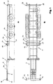
- the crossbar 10 is shown in an enlarged plan view.
- the locking housings 12 at the ends, in which the plug pins 14 are movably mounted in the axial direction.
- the plug pins are shown in their extended position.
- the lock housings serve not only for mounting the plug pins 14, but also for holding twist locks 16 in the vertical direction, while the plug pins 14 extend horizontally and in the longitudinal direction of the container chassis (cf. also FIG. 1b), but counter to the direction of travel.
- the plug pin and the twist lock 16 are arranged in the locking housing 12 so that the central axis of the clamping bolt of the twist lock 16 intersects the central axis of the plug pin 14 at right angles.
- FIGS. 3a and b show a vertical cross section along the line III-III of FIG. 2 and FIG. 3b shows a horizontal longitudinal section.
- the locking housing 12 is hollow and receives a guide part 30 on which the plug pin 14 sits, which projects outwards through an opening 31 in the locking housing 12.
- the guide part 30 is dimensioned and mounted within the hollow locking housing such that it is in the axial direction of the plug pin 14 between a first position in which the plug pin 14 is completely extended from the locking housing 12 (shown in solid lines in FIGS.
- the guide member 30 is with a straight slot or Provide slot 32 through which the clamping bolt 34 of the twist lock 16 extends at right angles to the direction of movement of the guide part 30.
- the diameter of the clamping bolt 34 is only slightly smaller than the width of the elongated hole 32.
- the clamping bolt 34 is stationary in the locking housing 12, but is rotatably mounted.
- the clamping bolt 34 carries at its upper end the locking head 36 of the twist lock 16, which is arranged on the top of the locking housing 12.
- the clamping bolt 34 protrudes from the underside of the locking housing 12 and is provided at its lower end 35 with a clamping nut, not shown in the figures.
- the clamping bolt 34 of the twist lock 16 together with the elongated hole 32 of the guide part 30 receiving it, serves as a guide device which ensures that the plug pin 14 is axially movable but prevents movement in the transverse direction.
- the central axis of the elongated hole 32 coincides with the central axis of the plug pin 14 and is cut at right angles from the central axis of the clamping bolt 34.
- the outer sides of the guide part 30 rest loosely on the facing inner sides of the locking housing 12.
- the guide part 30 has a substantially flat O-shape.
- a small guide pin 38 sits on the upper side of the guide part 30 and is loosely inserted in a recess 40 at one end of a pivot lever 42.
- the pivot lever 42 is held on the crossbar 10 and about an axis of rotation 44 pivotable.
- the pivot lever 42 sits outside the locking housing 12 and projects through an opening 46 into it so that the recess 40 can grip around the pin 38 of the guide part 30 arranged in the locking housing 12 at one end.
- the pivot lever 42 is shown in solid lines in a position in which the plug pin 14 is fully extended, and in dash-dotted lines in a further position in which the plug pin 14 is fully inserted into the locking housing 12.
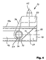
- twist locks 20 at the two ends of the second crossbar 18 is explained in more detail below with reference to FIGS. 4 and 5.
- the twist lock 20 is held in a twist lock housing 50 which has two plate-shaped side legs 51, 52 which are arranged parallel and at a distance from one another and which are connected to one another by a plate-shaped upper part 53 and a rib element 54 arranged below this.
- each twist-lock housing 50 is pivotally supported on the crossbar 18 by means of a pivot pin 56.
- the crossbeam 18 consists of two spaced and parallel to each other cross member, between which the twist lock housing of each of the two twist locks 20 is arranged and pivotally supported.
- the twist-lock housing 50 has a sleeve 58 which connects the two side parts 51, 52 on the inside with one another, as can be seen in FIG. 5b.
- Corresponding holes are provided in the two truss parts through which the ends of the Sleeve 58 received pivot pin 56 for pivoting mounting of the twist lock housing 50 protrude.
- the axis of rotation of the pivot pin 56 runs horizontally and in the direction of travel and transversely to the crossbar 18, so that the twist-lock housing 50 can be pivoted transversely to the direction of travel.
- the rib element 54 has a bore for the rotatable mounting of the clamping bolt 60 of the twist lock 20.
- the upper end of the clamping bolt 60 protrudes from the upper part 53 of the twist lock housing 50 and carries the locking head 62, while the clamping and rotating nuts 64, 66 are arranged below the rib element 54 within the twist lock housing 50.
- a plate-shaped element 68 is fastened between the bore 57 and the outermost end 19 on the inner sides of the two cross member parts.
- This plate-shaped element 19 is provided with an edge 69 which faces the opening 57 and thus the central axis of the container chassis and is inclined such that the lower end of the edge 69 is less distant from the central axis of the container chassis than the upper end has (see FIG. 4).
- the side parts 51, 52 of the twist-lock housing 50 are provided with a corresponding edge 70 which is arranged such that it is essentially flat on the edge 69 of the element in the working position of the twist-lock housing 50 shown in FIG 68 rests.
- the element 68 serves as a stop and support element for holding the twist-lock housing 50 in the working position in which the axis of rotation of the clamping bolt 60 of the twist-lock 20 is directed vertically, so that the locking head 62 projects upwards and the outer surface of the Upper part 53 of the twist lock housing 50 forms a horizontal support surface for a container of the short design.
- the edge 70 of the twist-lock housing 50 rests securely on the edge 69 of the element 68, so that special locking means for locking the twist-lock housing 50 are not absolutely necessary.
- the element 68 has a further edge 72 which faces the central axis of the container chassis and which essentially adjoins the lower end of the inclined edge 69 vertically.
- This edge 72 serves as a stop for the twist-lock housing 50 when it is pivoted into the rest position. In the rest position, the twist-lock housing 50 then lies against this edge 72 with the edge 74 opposite the edge 70, as a result of which further pivoting or oscillation of the twist-lock housing 50 in its rest position is prevented.
- twist-lock housing 50 If the twist-lock housing 50 is now to be brought into its rest position from its working position shown in FIG. 4, it only has to be pivoted downwards in the direction of arrow 76 between the two cross-member parts of the cross-member 18. In the rest position, the twist-lock housing 50 is located completely below the support plane formed by the upper side 18a of the crossbar 18. The swivel angle is a maximum of approximately 180 °.
- twist-lock housings 50 are in the rest position at the ends of the second crossbar 18 pivoted because the container must rest on the top 18a of the second crossbar 18 and the twist locks 20 are not needed in their working position, but then only interfere. If, on the other hand, two containers of the short design are to be used, the twist-lock housings 50 are pivoted in their working position, since the twist-locks 20 are then required to lock the rear of the front container.
- the height of the twist-lock housings 50 are dimensioned such that in the working position the surface of the upper side 53 forms a common support plane with the support surface 4a of the front section 4 of the container chassis 2.
- FIGS. 6 and 7 show further versions of locking housings 12 'and 12' 'which differ from the version shown in FIG. 3 in that a twist lock is not provided and a bolt 80 instead of the twist lock clamping bolt is fastened in the housing 12 'and 12' ', which extends at right angles to the direction of movement of the guide part 30 and thus to the axis of the plug pin 14.
- the diameter of the bolt 80 is only slightly smaller than the width of the elongated hole 32.
- the bolt 80 has a hexagon head at one end and a threaded section at its other end, onto which a nut is screwed in order to secure the bolt 80 in the locking housing 12 'or 12' '.
- the bolt 80 is stationary and fixed in the locking housing 12 'or 12' '.
- FIGS. 6 and 7 differ from the version in FIG. 3 in that the pivot lever 42 is located directly on the locking housing 12 'or 12''is pivotally mounted about its axis of rotation 44.
- a fork bearing 82 is provided on the end face 12a 'of the locking housing 12', on which the pivot lever 42 is pivotably supported with the aid of an articulated bolt 84.
- pivot lever 42 in the embodiment of FIG. 7 is mounted directly in the housing with the aid of the articulation pin 84 between two side walls 12a ′′ and 12b ′′ and protrudes therefrom.
- FIGS. 6 and 7 form separate units from the cross member 10, which are manufactured independently of the cross member 10 and then only have to be attached to the ends of the cross member 10, preferably by welding. This eliminates the need for adjustment work on the cross member, which can sometimes lead to problems with regard to the strength and statics of the cross member.
- the locking housing 12 'shown in Figure 6 is attached with its end face 12a' to the open end of the cross member 10 so that the pivot lever 42 protrudes into the cavity of the cross member 10.
- the pivot lever 42 can then be operated through openings formed in the cross member 10.
- FIGS. 6 and 7 have the same design features as the design of FIG. 3.
- the outside of the guide part 30 lies loosely against the facing inside of the locking housing 12 'or 12' 'and is thus also guided from the inside of the locking housing.
- the pivot lever 42 also has at one end the recess with which it can grip around the pin 38 seated on the guide part 30.
Abstract
Description
Die Erfindung betrifft eine Vorrichtung zur Verriegelung eines Containers an einem Fahrzeugchassis, mit einem an einem Teil des Fahrzeugchassis gelagerten und in axialer Richtung zwischen einer eingefahrenen und einer ausgefahrenen Stellung bewegbaren Steckzapfen, der in seiner ausgefahrenen Stellung in einen Verriegelungsbeschlag eines am Fahrzeugchassisteil in Anlage gebrachten Containers eingreift.The invention relates to a device for locking a container on a vehicle chassis, with a pin mounted on a part of the vehicle chassis and movable in the axial direction between a retracted and an extended position, which in its extended position in a locking fitting of a container brought into contact with the vehicle chassis part intervenes.
Eine solche Vorrichtung ist bekannt und wird insbesondere an den beiden Enden der vordersten Quertraverse eines Sattelaufliegers für Container vorgesehen. Dabei dient diese Traverse nicht zur Auflage, sondern lediglich zur Anlage eines auf dem Sattelauflieger liegenden Containers. Der Container wird zum Transport auf den Sattellieger aufgelegt und soweit in Fahrtrichtung auf dem Sattelauflieger verschoben, bis der Container in Anlage an die vorderste Quertraverse gelangt. Dann werden die Steckzapfen an den Enden der vordersten Quertraverse ausgefahren, damit diese in die entsprechenden Verriegelungsbeschläge des Containers eingreifen können, wozu der Container allerdings entsprechend ausgerichtet sein muß.Such a device is known and is provided in particular at the two ends of the foremost crossbar of a semi-trailer for containers. It serves this crossbeam does not serve as a support, but only for the installation of a container lying on the semi-trailer. The container is placed on the saddle carrier for transport and moved in the direction of travel on the semi-trailer until the container comes into contact with the front crossbar. Then the plug pins are extended at the ends of the foremost crossbar so that they can engage in the corresponding locking fittings of the container, for which purpose the container must be aligned accordingly.
Es hat sich jedoch herausgestellt, daß der Herstellungsaufwand für die Lagerung und Führung der herkömmlichen Steckzapfen besonders hoch ist. Dies liegt an einer im allgemeinen recht komplizierten Ausbildung der Lagerung und Führung des Steckzapfens am zugehörigen Fahrzeugchassisteil.However, it has been found that the manufacturing outlay for storing and guiding the conventional plug pins is particularly high. This is due to the generally quite complicated design of the mounting and guidance of the plug pin on the associated vehicle chassis part.
Es ist daher Aufgabe der Erfindung, die Lagerung und Führung eines solchen Steckzapfens einer Vorrichtung der eingangs genannten Art zu vereinfachen.It is therefore an object of the invention to simplify the storage and guidance of such a plug pin of a device of the type mentioned.
Diese Aufgabe wird dadurch gelöst, daß der Steckzapfen der Vorrichtung der eingangs genannten Art an einem ersten Führungselement sitzt, das eine längliche und sich axialer Richtung des Steckzapfens erstreckende Ausnehmung aufweist, in oder durch die ein am Fahrzeugchassisteil vorgesehenes und gegenüber der Bewegung des Steckzapfens feststehendes zweites Führungselement ragt.This object is achieved in that the plug of the device of the type mentioned sits on a first guide element which has an elongated and axial direction of the plug extending recess, in or through which a provided on the vehicle chassis part and fixed against the movement of the plug second Guide element protrudes.
Die erfindungsgemäße Lagerung und Führung des Steckzapfens wird mit Hilfe des den Steckzapfen tragenden ersten Führungselementes in Zusammenwirkung mit dem feststehenden zweiten Führungselement erreicht. Dabei ragt das zweite Führungselement in oder durch eine am ersten Führungselement vorgesehene Ausnehmung. Dadurch, daß diese Ausnehmung in länglicher Form ausgebildet ist und sich in axialer Richtung des Steckzapfens erstreckt, bleibt die axiale Bewegbarkeit des Steckzapfens aufrechterhalten, während eine Bewegung des ersten Führungselementes quer zur Achse des Steckzapfens durch das feststehende und in oder durch die Ausnehmung des ersten Führungselementes ragende zweite Führungselement verhindert wird.The storage and guidance of the plug pin according to the invention is carried out with the aid of the first one carrying the plug pin Guide element achieved in cooperation with the fixed second guide element. The second guide element projects into or through a recess provided on the first guide element. Characterized in that this recess is elongated and extends in the axial direction of the plug pin, the axial mobility of the plug pin is maintained, while a movement of the first guide element transversely to the axis of the plug pin through the fixed and in or through the recess of the first guide element protruding second guide element is prevented.
Mit Hilfe der Erfindung wird also eine einfache, jedoch zugleich sichere Lagerung und Führung des Steckzapfens geschaffen. Durch die Einfachheit der erfindungsgemäßen Anordnung können die Herstellungskosten in nicht unerheblicher Weise gesenkt werden. Als weiterer Vorteil ist die platzsparende Bauform der erfindungsgemäßen Anordnung zu nennen. Außerdem läßt sich die erfindungsgemäße Vorrichtung besonders einfach an der Außenseite eines Fahrzeugchassisteils anbringen, was insbesondere bei einer Nachrüstung eines Fahrzeugchassis mit der erfindungsgemäßen Vorrichtung von Vorteil ist.With the help of the invention, a simple, but at the same time safe storage and guidance of the plug is created. Due to the simplicity of the arrangement according to the invention, the manufacturing costs can be reduced in a not inconsiderable manner. Another advantage is the space-saving design of the arrangement according to the invention. In addition, the device according to the invention can be particularly easily attached to the outside of a vehicle chassis part, which is particularly advantageous when retrofitting a vehicle chassis with the device according to the invention.
Vorzugsweise sind der Steckzapfen und das zweite Führungselement in einem separaten, am Fahrzeugchassisteil befestigbaren Gehäuse gelagert. Bei einer derartigen Konstruktion braucht das Fahrzeugchassisteil im wesentlichen nicht besonders angepaßt oder verändert zu werden; lediglich das Gehäuse muß an diesem befestigt werden.The plug pin and the second guide element are preferably mounted in a separate housing which can be fastened to the vehicle chassis part. With such a construction, the vehicle chassis part does not essentially need to be specially adapted or changed; only the housing has to be attached to it.
Gemäß einer bevorzugten Weiterbildung dieser Ausführung ist das zweite Führungselement von einem an mindestens einer Gehäusewand befestigten Bolzen gebildet.According to a preferred development of this embodiment the second guide element is formed by a bolt fastened to at least one housing wall.
Es gibt aber auch Anwendungsfälle, bei denen der Container nicht in Anlage an das entsprechende Fahrzeugchassisteil gebracht werden kann, sondern auf diesen aufgelegt werden muß, beispielsweise weil dieser Container eine andere Länge oder Form besitzt, die eine andere Anordnung auf dem Fahrzeugchassis nicht erlauben. Für diese Fälle muß dann ein zusätzlicher Twist-Lock vorgesehen werden. In der Vergangenheit hat sich jedoch gezeigt, daß der Einbau eines Twist-Locks im Fahrzeugchassisteil im Bereich des axial bewegbaren Steckzapfens Probleme insofern bereitet, als der Twist-Lock und der Steckzapfen sich in Anordnung und Funktion nicht gegenseitig behindern. Dies führte zu komplizierten Anordnungen, die einen hohen Herstellungsaufwand und somit hohe Kosten verursachten.However, there are also applications in which the container cannot be brought into contact with the corresponding vehicle chassis part, but must be placed on it, for example because this container has a different length or shape that does not allow a different arrangement on the vehicle chassis. An additional twist lock must then be provided for these cases. In the past, however, it has been shown that the installation of a twist lock in the vehicle chassis part in the region of the axially movable plug poses problems insofar as the twist lock and the plug pin do not interfere with one another in terms of arrangement and function. This led to complicated arrangements, which caused high manufacturing costs and thus high costs.
Gemäß einem weiteren wichtigen Aspekt dieser Erfindung wurde zur Lösung dieses Problemes gefunden, daß das zweite Führungselement vom Spannbolzen eines am Fahrzeugchassisteil angeordneten Twist-Locks gebildet werden kann, der in Eingriff mit einem Verriegelungsbeschlag eines auf das Fahrzeugchassisteil aufliegenden Containers bringbar ist. Bei dieser Ausführung werden also der Twist-Lock und der Steckzapfen in ihrer Anordnung erfindungsgemäß so kombiniert, daß der Spannbolzen des Twist-Locks durch die Ausnehmung im ersten Führungselement, an dem der Steckzapfen sitzt, geführt ist. Mit Hilfe der Erfindung wird also in besonders geschickter Weise eine Anordnung von Steckzapfen und Twist-Lock geschaffen, welche nicht nur eine besonders einfache Konstruktion ermöglicht, sondern auch nur einen geringen Platzbedarf und somit kleine Bauform erfordert, ohne daß die Funktionen von Steckzapfen und Twist-Lock gegenseitig beeinflußt werden.According to a further important aspect of this invention, it has been found to solve this problem that the second guide element can be formed by the tensioning bolt of a twist lock arranged on the vehicle chassis part, which can be brought into engagement with a locking fitting of a container resting on the vehicle chassis part. In this embodiment, the twist lock and the plug pin are combined in their arrangement according to the invention so that the clamping bolt of the twist lock is guided through the recess in the first guide element on which the plug pin is seated. With the help of the invention, an arrangement of plug pins and twist-lock is thus created in a particularly clever manner, which not only enables a particularly simple construction, but also only requires a small amount of space and thus requires a small design without the functions of the plug pin and twist lock being influenced by one another.
Vorzugsweise erstreckt sich das zweite Führungselement rechtwinklig zum Steckzapfen, wodurch eine besonders gute Führung und axiale Bewegbarkeit des Steckzapfens erzielt wird. Zweckmäßigerweise schneidet die Mittelachse des zweiten Führungselementes die Mittelachse des Steckzapfens, wodurch nicht nur die Bauform der gesamten Anordnung besonders klein gehalten werden kann, sondern auch die Ausrichtung des Containers erleichtert wird, wenn das zweite Führungselement vom Spannbolzen eines Twist-Locks gebildet wird.The second guide element preferably extends at right angles to the plug pin, as a result of which particularly good guidance and axial mobility of the plug pin is achieved. The central axis of the second guide element expediently intersects the central axis of the plug pin, as a result of which not only the design of the entire arrangement can be kept particularly small, but also the alignment of the container is facilitated if the second guide element is formed by the clamping bolt of a twist lock.
Eine Weiterbildung der erfindungsgemäßen Vorrichtung mit integriertem zusätzlichem Twist-Lock zeichnet sich dadurch aus, daß der Steckzapfen horizontal angeordnet ist und in seiner ausgefahrenen Stellung in einen Verriegelungsbeschlag eines seitlich am Fahrzeugchassisteil anliegenden Containers eingreift und daß sich der Spannbolzen des Twist-Locks in vertikaler Richtung erstreckt und dessen Verriegelungskopf am oberen Ende des Spannbolzens und vorzugsweise auf der Oberseite des Fahrzeugchassisteils angeordnet ist, wodurch der Twist-Lock in Eingriff mit einem Verriegelungsbeschlag eines auf der Oberseite des Fahrzeugchassisteils aufliegenden Containers bringbar ist.A further development of the device according to the invention with an integrated additional twist lock is characterized in that the plug pin is arranged horizontally and, in its extended position, engages in a locking fitting of a container lying on the side of the vehicle chassis part and in that the clamping bolt of the twist lock extends in the vertical direction and the locking head of which is arranged at the upper end of the clamping bolt and preferably on the top of the vehicle chassis part, as a result of which the twist lock can be brought into engagement with a locking fitting of a container resting on the top of the vehicle chassis part.
Bei einer gegenwärtig besonders bevorzugten Ausführung besteht die Ausnehmung im ersten Führungselement, an dem der Steckzapfen sitzt, aus einem Langloch oder Schlitz. Alternativ kann das Führungselement beispielsweise aber auch die Form einer Gabel mit zwei im Abstand voneinander angeordneten Schenkeln besitzen, zwischen denen die Ausnehmung gebildet ist.In a currently particularly preferred embodiment, the recess in the first guide element on which the plug is seated consists of an elongated hole or slot. Alternatively, the guide element can, for example, also have the shape of a fork with two spaced apart have arranged legs, between which the recess is formed.
Der Steckzapfen kann mittels eines Schwenkhebels bewegt werden. Vorzugsweise kann der Schwenkhebel entweder am Fahrzeugchaussisteil oder am Gehäuse gelagert sein. Hierzu kann vorzugsweise am ersten Führungselement ein Stift angebracht sein, der lose in eine an einem Ende des Schwenkhebels vorgesehene Aussparung ragt.The plug pin can be moved using a swivel lever. The pivot lever can preferably be mounted either on the vehicle body part or on the housing. For this purpose, a pin can preferably be attached to the first guide element, which pin projects loosely into a recess provided at one end of the pivot lever.
Gewöhnlich erstreckt sich der Steckzapfen in Längsrichtung des Fahrzeugchassis, so daß dieser in eine seitliche Öffnung eines Verriegelungsbeschlages eines am Fahrzeugchassisteil in Anlage gebrachten Containers eingreift.Usually, the plug extends in the longitudinal direction of the vehicle chassis, so that it engages in a lateral opening of a locking fitting of a container which has been brought into contact with the vehicle chassis part.
Eine weitere gegenwärtig besonders bevorzugte Ausführung der Erfindung zeichnet sich dadurch aus, daß das Fahrzeugchassis ein Container-Chassis in Gooseneck-Ausführung ist und an dessen vorderster Quertraverse mindestens ein sich entgegen der Fahrtrichtung erstreckender Steckzapfen gelagert ist.Another currently particularly preferred embodiment of the invention is characterized in that the vehicle chassis is a container chassis in a Gooseneck design and on its front cross-member at least one plug extending in the opposite direction to the direction of travel is mounted.
Solche Container-Chassis werden in einer Ausführung verwendet, die in einen kürzeren vorderen Längsabschnitt und einen längeren hinteren Längsabschnitt unterteilt ist. Der längere hintere Abschnitt ist tiefergelegt, um Container mit größerer Höhe verwenden zu können, da die Höhe der Container und sonstige Aufbauten durch die maximal zulässige Durchfahrthöhe unter Brücken, Unterführungen etc. begrenzt ist. Der längere hintere Abschnitt des Container-Chassis ist derart tiefergelegt, daß der kürzere vordere Abschnitt, auch Gooseneck-Teil genannt, oberhalb der Auflageebene des längeren hinteren Abschnittes angeordnet ist, da der Königzapfen auf einer bestimmten definierten Höhe liegen muß, um in die Kupplung des Sattelschleppers passen zu können, und somit der kürzere vordere Abschnitt nicht tiefergelegt werden kann. Zwischen vorderem und hinterem Abschnitt des Container-Chassis wird demnach ein Absatz gebildet. Damit ein Container mit einer Länge, die der Gesamtlänge des Container-Chassis entspricht, gleichwohl sicher auf diesem aufgelegt und befestigt werden kann, muß die Wandung im vorderen Bereich der Unterseite des Containers mit einem nach innen ragenden, zurückgenommenen Abschnitt, auch Gooseneck-Tunnel genannt, zur Bildung einer zurückspringenden Ausnehmung für die Aufnahme des vorderen Abschnittes versehen sein. Am vordersten Ende des kürzeren vorderen Abschnittes des Container-Chassis sitzt eine Quertraverse, auf der der Container aufgrund der zuvor beschriebenen Konstruktion nicht aufliegt, sondern an deren Rückseite sich der Container mit dem unteren Abschnitt seiner Vorderseite in Anlage befindet, wobei die an den Enden der vordersten Quertraverse gelagerten Steckzapfen in ihrer ausgefahrenen Stellung in seitliche Öffnungen der zugewandten Verriegelungsbeschläge des Containers eingreifen.Such container chassis are used in an embodiment which is divided into a shorter front longitudinal section and a longer rear longitudinal section. The longer rear section is lowered in order to be able to use containers with a greater height, since the height of the containers and other superstructures is limited by the maximum permissible passage height under bridges, underpasses, etc. The longer rear section of the container chassis is lowered so that the shorter front section, also called the gooseneck part, lies above the support plane of the longer rear section Section is arranged because the kingpin must be at a certain defined height to be able to fit into the coupling of the articulated lorry, and thus the shorter front section cannot be lowered. A shoulder is therefore formed between the front and rear section of the container chassis. So that a container with a length that corresponds to the overall length of the container chassis can nevertheless be securely placed and fastened on it, the wall in the front area of the underside of the container must have an inwardly projecting, recessed section, also called a Gooseneck tunnel , To be provided with a recessed recess for receiving the front section. At the foremost end of the shorter front section of the container chassis is a crossbar on which the container does not rest due to the construction described above, but on the back of which the container is in contact with the lower section of its front, the ends of which In the extended position, the front cross-beam mounted plug pins engage in lateral openings in the facing locking fittings of the container.
Es gibt aber nun auch Fälle, in denen auf dem Containerchassis der zuvor beschriebenen Gooseneck-Ausführung Container transportiert werden sollen, welche einen Gooseneck-Tunnel nicht aufweisen. Diese Container müssen dann zwangsläufig mit ihrer ebenen Unterseite auf der Oberseite des vorderen Abschnittes aufliegen, was jedoch zur Folge hat, daß die Steckzapfen an der vordersten Quertraverse nicht zur Befestigung solcher Container verwendet werden können, da die entsprechenden Verriegelungsbeschläge dieser Container oberhalb der Steckzapfen liegen. In solchen Fällen wird der Container ein wenig, im allgemeinen entsprechend der Breite der vordersten Quertraverse, nach vorne verschoben, so daß der Container nun auf der vordersten Quertraverse aufliegt. Nun kann der Container an seiner Vorderseite mit Hilfe der Twist-Locks fixiert werden, die in der erfindungsgemäßen Anordnung gemeinsam mit den Steckzapfen an den beiden Enden der vordersten Quertraverse vorgesehen sind und dessen Spannbolzen durch die Ausnehmungen der die Steckzapfen tragenden ersten Führungselemente gesteckt sind. Mit Hilfe der erfindungsgemäßen Anordnung kann somit ein Container-Chassis in Gooseneck-Ausführung sowohl für den Transport von Containern mit Gooseneck-Tunnel als auch für den Transport von herkömmlichen Containern ohne Gooseneck-Tunnel und somit wesentlich vielseitiger als die herkömmlichen Container-Chassis dieser Art verwendet werden.However, there are also cases in which containers that do not have a gooseneck tunnel are to be transported on the container chassis of the previously described gooseneck version. These containers must then inevitably rest with their flat underside on the top of the front section, which has the consequence, however, that the plug pins on the foremost crossbar cannot be used to fasten such containers, since the corresponding locking fittings of these containers above the plug pins lie. In such cases, the container is moved forward a little, generally according to the width of the foremost crossbar, so that the container now rests on the foremost crossbar. Now the container can be fixed on its front side with the aid of the twist locks, which are provided in the arrangement according to the invention together with the plug pins at the two ends of the foremost crossbar and the clamping bolts of which are inserted through the recesses of the first guide elements carrying the plug pins. With the help of the arrangement according to the invention, a container chassis in gooseneck design can thus be used both for the transport of containers with gooseneck tunnels and for the transport of conventional containers without gooseneck tunnels and thus much more versatile than the conventional container chassis of this type will.
In diesem Zusammenhang ist eine weitere gegenwärtig besonders bevorzugte Ausführung der Erfindung vorgesehen, welche mindestens einen zusätzlichen Twist-Lock aufweist, der an einer zusätzlichen Quertraverse angebracht ist, die in einem der Länge eines Containers entsprechenden Abstand zur vordersten Quertraverse angeordnet ist, und welche dadurch gekennzeichnet ist, daß der zusätzliche Twist-Lock an einem Tragelement installiert ist, das zwischen einer Arbeitsstellung, in der der Twist-Lock mit einem Verriegelungsbeschlag eines auf dem Fahrzeugchassis aufliegenden Containers in Eingriff bringbar ist, und einer Ruhestellung, in der sich der Twist-Lock außer Eingriff mit dem Verriegelungsbeschlag des Containers und in einem Abstand zum Container befindet, bewegbar am Fahrzeugchassis gehaltert ist.In this context, another currently particularly preferred embodiment of the invention is provided, which has at least one additional twist lock, which is attached to an additional crossbar, which is arranged at a distance corresponding to the length of a container from the foremost crossbar, and which is characterized thereby is that the additional twist lock is installed on a support element, which is between a working position in which the twist lock can be brought into engagement with a locking fitting of a container resting on the vehicle chassis, and a rest position in which the twist lock out of engagement with the locking fitting of the container and at a distance from the container, is movably mounted on the vehicle chassis.
Diese Ausführung hat insbesondere den Vorteil, daß ein auf einem Container-Chassis in Gooseneck-Ausführung aufgesetzter herkömmlicher Container ohne Gooseneck-Tunnel auch an seiner Hinterseite sicher befestigt werden kann. In diesem Fall werden nämlich die zusätzlichen Twist-Locks in ihre Arbeitsstellung bewegt, in der sie mit den entsprechenden Verriegelungsbeschlägen dieses Containers in Eingriff bringbar sind. Wenn dagegen Container und insbesondere Container mit Gooseneck-Tunnel transportiert werden sollen, welche dann an ihrer Vorderseite mit Hilfe der ausgefahrenen Steckzapfen arretiert werden, kann es vorkommen, daß die zusätzlichen Twist-Locks stören, wenn eine Ausrichtung zu Verriegelungsbeschlägen des Containers aufgrund ihrer Lage nicht möglich ist. In solchen Fällen können diese zusätzlichen Twist-Locks bei dieser erfindungsgemäßen Ausführung in eine Ruhestellung bewegt werden, in der sie die Auflage des Containers auf dem Fahrzeugchassis nicht behindern. Dabei sollte sich das Twist-Lock-Tragelement in der Ruhestellung vollständig unter der auf dem Fahrzeugchassis gebildeten Auflageebene des Containers befinden.This version has the particular advantage that a conventional container placed on a container chassis in a Gooseneck version can also be securely attached to its rear without a Gooseneck tunnel. In this case, the additional twist locks are moved into their working position, in which they can be brought into engagement with the corresponding locking fittings of this container. If, on the other hand, containers and in particular containers with a gooseneck tunnel are to be transported, which are then locked on the front side with the aid of the extended plug pins, it may happen that the additional twist locks interfere if alignment with the container's lock fittings is not due to their position is possible. In such cases, these additional twist locks can be moved into a rest position in this embodiment according to the invention, in which they do not hinder the support of the container on the vehicle chassis. In the rest position, the twist-lock support element should be completely below the support level of the container formed on the vehicle chassis.
Vorzugsweise ist das Twist-Lock-Tragelement zwischen der Arbeits- und der Ruhestellung schwenkbar am Fahrzeugchassis gehaltert. Bei einer gegenwärtig besonders bevorzugten Weiterbildung dieser Ausführung verläuft die Schwenkachse in Richtung der Längserstreckung des Fahrzeugchassis und ist somit das Twist-Lock-Tragelement quer zur Längserstreckung des Fahrzeugchassis verschwenkbar. Dadurch ist das Twist-Lock-Tragelement auch quer zur Fahrtrichtung des Fahrzeugchassis verschwenkbar, so daß ein unbeabsichtigtes Verschwenken des Twist-Lock-Gehäuses durch in Fahrtrichtung auftretende Brems- und Beschleunigungskräfte im wesentlichen nicht möglich ist. Zweckmäßigerweise sollte das Twist-Lock-Tragelement zur Mitte des Fahrzeugchassis hin verschwenkbar sein.The twist-lock support element is preferably pivotally mounted on the vehicle chassis between the working and the rest position. In a currently particularly preferred development of this embodiment, the pivot axis runs in the direction of the longitudinal extent of the vehicle chassis and the twist-lock support element can thus be pivoted transversely to the longitudinal extent of the vehicle chassis. As a result, the twist-lock support element can also be pivoted transversely to the direction of travel of the vehicle chassis, so that unintentional pivoting of the twist-lock housing by braking and acceleration forces occurring in the direction of travel is essentially not possible is. The twist-lock support element should expediently be pivotable toward the center of the vehicle chassis.
Bei einer weiteren Ausführung der Erfindung verläuft die Drehachse des Spannbolzens des Twist-Locks in einem Abstand zur Schwenkachse des Twist-Lock-Tragelementes, wobei der Verriegelungskopf des Twist-Locks in einem Abstand zur Schwenkachse des Twist-Locks-Tragelementes angeordnet und von der Schwenkachse im wesentlichen weggerichtet ist. Zur Arretierung des Twist-Lock-Tragelementes in der Arbeitsstellung sollte vorzugsweise am Fahrzeugchassis ein erster Anschlag befestigt sein, auf dem das Twist-Lock-Tragelement in der Arbeitsstellung aufliegt. Dieser Anschlag kann eine rechtwinklig zur Schwenkebene und winklig zur Schwenkrichtung des Twist-Lock-Tragelementes angeordnete Auflagefläche aufweisen, auf der das Twist-Lock-Tragelement mit einer entsprechend ausgebildeten Fläche in der Arbeitsstellung aufliegt. Mit dieser Ausführung wird eine konstruktiv besonders einfache Anordnung geschaffen, mit der das Twist-Lock-Tragelement sicher in der Arbeitsstellung gehalten wird und eine definierte Lage einnimmt.In a further embodiment of the invention, the axis of rotation of the clamping bolt of the twist lock runs at a distance from the pivot axis of the twist lock support element, the locking head of the twist lock arranged at a distance from the pivot axis of the twist lock support element and from the pivot axis is essentially directed away. To lock the twist-lock support element in the working position, a first stop should preferably be attached to the vehicle chassis, on which the twist-lock support element rests in the working position. This stop can have a support surface arranged at right angles to the swivel plane and at an angle to the swivel direction of the twist lock support element, on which the twist lock support element rests with a correspondingly designed surface in the working position. With this design, a structurally particularly simple arrangement is created with which the twist-lock support element is held securely in the working position and occupies a defined position.
Damit auch das Twist-Lock-Tragelement in der Ruhestellung eine definierte Lage einnehmen kann, sollte am Fahrzeugchassis ebenfalls ein zweiter Anschlag befestigt sein, an den das Twist-Lock-Tragelement in der Ruhestellung anstößt. Der Schwenkwinkel sollte zweckmäßigerweise auf maximal 180° begrenzt sein.So that the twist-lock support element can also assume a defined position in the rest position, a second stop should also be attached to the vehicle chassis, which the twist-lock support element abuts in the rest position. The swivel angle should expediently be limited to a maximum of 180 °.
Im allgemeinen steht in der Arbeitsstellung der Spannbolzen des Twist-Locks im wesentlichen vertikal, um eine sichere Befestigung des auf dem Fahrzeugchassis aufgelegten Container zu gewährleisten.In general, the tensioning bolt of the twist lock stands essentially vertically in the working position in order to ensure secure fastening of the container placed on the vehicle chassis.
Eine weitere gegenwärtig besonders bevorzugte Weiterbildung zeichnet sich dadurch aus, daß an beiden Enden der vordersten Quertraverse jeweils ein Steckzapfen und an beiden Enden einer weiteren Quertraverse jeweils ein zusätzlicher Twist-Lock vorgesehen ist und daß die Auflageflächen der vordersten Quertraverse und des Twist-Lock-Tragelementes an der weiteren Quertraverse in einer gemeinsamen Ebene liegen, die vorzugsweise parallel zur Fahrbahnoberfläche verläuft.Another currently particularly preferred further development is characterized in that a plug pin is provided on both ends of the foremost crossbar and an additional twist lock is provided on both ends of a further crossbar and in that the contact surfaces of the foremost crossbar and the twist lock support element lie on the further crossbar in a common plane, which preferably runs parallel to the road surface.
Nachfolgend wird ein bevorzugtes Ausführungsbeispiel der erfindungsgemäßen Vorrichtung anhand der beiliegenden Zeichnungen näher erläutert. Es zeigen:
- Figur 1
- ein Container-Chassis in Gooseneck-Ausführung in Seitenansicht (Figur 1a) und in Draufsicht (Figur 1b);
- Figur 2
- eine vergrößerte Darstellung der vordersten Quertraverse in Draufsicht mit Verriegelungen in einer ersten Ausführung;
- Figur 3
- einen Querschnitt durch ein endseitiges Verriegelungsgehäuse der vordersten Quertraverse von Figur 2 entlang der Linie III-III (Figur 3a) und einen Längsschnitt durch dieses Verriegelungsgehäuse (Figur 3b);
Figur 4- eine Seitenansicht des Endes einer weiteren Quertraverse;
Figur 5- in zwei unterschiedlichen Seitenansichten (Figuren 5a und b) ein an der
Quertraverse von Figur 4 gehaltertes Twist-Lock-Tragelement mit darin installiertem Twist-Lock; - Figur 6a - d
- verschiedene Ansichten eines an den Enden der vordersten Quertraverse anbringbaren Verriegelungsgehäuses mit Verriegelungen in einer zweiten Ausführung; und
- Figur 7
- einen Querschnitt (Figur 7a) durch ein auf den Enden der vordersten Quertraverse befestigbares Verriegelungsgehäuse mit Verriegelungen in einer dritten Ausführung und eine Frontalansicht (Figur 7b) dieses Verriegelungsgehäuses.
- Figure 1
- a container chassis in Gooseneck version in side view (Figure 1a) and in plan view (Figure 1b);
- Figure 2
- an enlarged view of the foremost crossbar in plan view with locks in a first embodiment;
- Figure 3
- a cross section through an end locking housing of the foremost crossbar of Figure 2 along the line III-III (Figure 3a) and a longitudinal section through this locking housing (Figure 3b);
- Figure 4
- a side view of the end of another crossbar;
- Figure 5
- in two different side views (FIGS. 5a and b) a twist-lock support element held on the cross-beam of FIG. 4 with a twist-lock installed therein;
- Figure 6a - d
- different views of one at the ends of the foremost crossbar attachable locking housing with locks in a second embodiment; and
- Figure 7
- a cross section (Figure 7a) through a lockable on the ends of the front crossbar locking housing with locks in a third embodiment and a front view (Figure 7b) of this locking housing.
In Figur 1 ist ein Container-Sattelauflieger bzw. Container-Chassis 2 in Gooseneck-Ausführung dargestellt. Das Container-Chassis 2 ist in einen kürzeren vorderen Abschnitt 4 und einen längeren hinteren Abschnitt 6 unterteilt. Wie Figur 1a deutlich erkennen läßt, ist der hintere Abschnitt 6 gegenüber dem vorderen Abschnitt tiefergelegt, so daß zwischen diesen beiden Abschnitten 4 und 6 ein Absatz 5 gebildet wird. Aufgrund des tiefergelegten Abschnittes 6 können mit dem dargestellten Container-Chassis 2 Container mit einer größeren Höhe transportiert werden, wobei die Höhe ja bekanntlich von der maximal zulässigen Durchfahrtshöhe unter Brücken, Unterführungen etc. begrenzt ist. Gegenüber dem hinteren Abschnitt 6 kann der vordere Abschnitt 4 nicht tiefergelegt werden, da die Lage des an der Unterseite des vorderen Abschnittes 4 befestigten Königzapfens 8 fest definiert und unveränderbar ist, und zwar in Anpassung an eine Kupplung eines Sattelschleppers.In Figure 1, a container semi-trailer or container chassis 2 is shown in Gooseneck version. The container chassis 2 is divided into a
Wie insbesondere Figur 1b erkennen läßt, ist am - in Fahrtrichtung betrachtet - vordersten Ende des vorderen Abschnittes 4 eine erste Quertraverse 10 vorgesehen, an deren beiden Enden jeweils ein Verriegelungsgehäuse 12 angebracht ist, welches einen in Fahrtrichtung nach hinten ragenden, axial bewegbaren Steckzapfen 14 und zusätzlich noch einen Twist-Lock 16 trägt. Etwa auf halber Länge weist das Container-Chassis 2 eine zweite Quertraverse 18 mit an den beiden Enden befestigten Twist-Lock-Gehäusen 20 und eine direkt danebenliegende dritte Quertraverse 22 mit an deren Enden angeordneten Twist-Locks 24 auf. Am hintersten Ende des Container-Chassis 2 sitzt dann schließlich noch eine vierte Quertraverse 26 mit an deren beiden Enden angebrachten Twist-Locks 28. Während die Oberseite der vordersten Quertraverse 10 mit der Auflagefläche 4a des vorderen Abschnitts 4 in einer gemeinsamen Ebene liegt, liegen die Oberseiten der Quertraversen 18, 22 und 26 und die Auflageebene 6a des hinteren Abschnittes 6 in einer gemeinsamen tieferen Ebene.As can be seen in particular in FIG. 1b, a
Das in Figur 1 dargestellte Container-Chassis 2 ist für den Transport von Containern der langen Bauart (40 Fuß oder 45 Fuß) vorgesehen, wobei die Unterseite dieser Container im vorderen Bereich mit einem nach innen ragenden und zurückgenommenen Abschnitt, auch Gooseneck-Tunnel genannt, ausgebildet ist, welcher zur Aufnahme des erhöhten vorderen Abschnittes 4 vorgesehen ist, damit ein solcher Container plan auf der Auflageebene 6a des längeren hinteren Abschnittes 6 aufliegen kann. Dabei liegt ein solcher Container nicht auf der Oberseite der ersten Quertraverse 10 auf, sondern nur seitlich an dieser an, wobei die Steckzapfen 14 in ihrer ausgefahrenen Stellung in die vorderen Öffnungen der beiden vorderen unteren Eckbeschläge des Containers greifen und den Container somit vorn arretieren. An der Hinterseite wird der Container von den Twist-Locks 28 der hintersten Quertraverse 26 gehalten.The container chassis 2 shown in FIG. 1 is intended for the transport of containers of the long type (40 feet or 45 feet), the underside of these containers in the front area with an inwardly projecting and recessed section, also called a gooseneck tunnel, is formed, which is provided for receiving the raised
Das dargestellte Container-Chassis ist jedoch nicht nur für den Transport von Containern der langen Bauart mit Gooseneck-Tunnel geeignet, sondern auch zum Transport von zwei Containern der kurzen Bauart (20 Fuß). Dabei liegt der eine kleine Container auf der hinteren Hälfte des Container-Chassis 2 auf der Auflagefläche 6a des hinteren Abschnittes 6 auf und wird von den Twist-Locks 24 und 28 der dritten und vierten Quertraversen 22 und 26 gehalten. Da die Container der kurzen Bauart nicht mit einem Gooseneck-Tunnel ausgerüstet sind, liegt der vordere Container auf der Auflagefläche 4a des vorderen Abschnittes 4 und gleichzeitig auch noch auf der vordersten Quertraverse 10, deren Oberseite mit der Auflagefläche 4a des vorderen Abschnittes fluchtet, auf und wird an seiner Vorderseite von den Twist-Locks 16 an den beiden Enden der vordersten Quertraverse 10 arretiert. An der hinteren Seite wird der Container von an den beiden Enden der zweiten Quertraverse 18 erhöht angebrachten Twist-Lock-Gehäusen im Abstand zur Auflagefläche 6a des hinteren Abschnittes gehalten und von den zugehörigen Twist-Locks 20 arretiert. Der vordere kurze Container sitzt demnach gegenüber dem hinteren Container um das Maß des Absatzes 5 höher, um daß der hintere Abschnitt 6 gegenüber dem vorderen Abschnitt tiefergelegt ist. Der vordere Container wird in diesem Fall somit an der vordersten Quertraverse 10 nicht von den Steckzapfen 14 gehalten, die zu diesem Zweck in die Quertraverse 10 eingefahren sind.However, the container chassis shown is not only Suitable for the transport of containers of the long type with Gooseneck tunnel, but also for the transport of two containers of the short type (20 feet). One of the small containers rests on the rear half of the container chassis 2 on the support surface 6a of the
In Figur 2 ist die Quertraverse 10 in vergrößerter Draufsicht dargestellt. Deutlich erkennt man die endseitig angesetzten Verriegelungsgehäuse 12, in denen die Steckzapfen 14 in axialer Richtung bewegbar gelagert sind. In Figur 2 sind die Steckzapfen in ihrer ausgefahrenen Stellung gezeigt. Die Verriegelungsgehäuse dienen nicht nur zur Lagerung der Steckzapfen 14, sondern auch zur Halterung von Twist-Locks 16 in vertikaler Richtung, während die Steckzapfen 14 sich horizontal und in Längsrichtung des Container-Chassis (vgl. hierzu auch Figur 1b), jedoch entgegen der Fahrtrichtung erstrecken. Dabei sind der Steckzapfen und der Twist-Lock 16 im Verriegelungsgehäuse 12 so angeordnet, daß die Mittelachse des Spannbolzen des Twist-Locks 16 die Mittelachse des Steckbolzens 14 rechtwinklig schneidet.In Figure 2, the
Die Anordnung von Steckzapfen 14 und Twist-Lock 16 im Verriegelungsgehäuse 12 ist im einzelnen den Figuren 3a und b zu entnehmen, von denen Figur 3a einen vertikalen Querschnitt entlang der Linie III-III von Figur 2 und Figur 3b einen horizontalen Längsschnitt zeigt. Wie aus diesen Figuren ersichtlich ist, ist das Verriegelungsgehäuse 12 hohl und nimmt ein Führungsteil 30 auf, an dem der Steckzapfen 14 sitzt, der durch eine Öffnung 31 im Verriegelungsgehäuse 12 nach außen ragt. Das Führungsteil 30 ist so dimensioniert und innerhalb des hohlen Verriegelungsgehäuses gelagert, daß es in axialer Richtung des Steckzapfens 14 zwischen einer ersten Stellung, in der der Steckzapfen 14 aus dem Verriegelungsgehäuse 12 vollständig ausgefahren ist (in Figuren 3a und b in durchgezogenen Linien dargestellt), und einer zweiten Stellung bewegbar ist, in der der Steckzapfen 14 vollständig in das Verriegelungsgehäuse 12 eingefahren ist (in den Figuren 3a und b in strichpunktierten Linien dargestellt), wobei im dargestellten Ausführungsbeispiel das Führungsteil 30 in seiner zweiten Stellung mit dem hinteren Ende aus einer weiteren Öffnung 33 des Verriegelungsgehäuses 12 ein wenig herausragt.The arrangement of plug pins 14 and twist-
Das Führungsteil 30 ist mit einem geraden Schlitz oder Langloch 32 versehen, durch das sich rechtwinklig zur Bewegungsrichtung des Führungsteils 30 der Spannbolzen 34 des Twist-Locks 16 erstreckt. Der Durchmesser des Spannbolzens 34 ist nur unwesentlich kleiner als die Breite des Langloches 32 gewählt. Der Spannbolzen 34 ist im Verriegelungsgehäuse 12 stationär, jedoch drehbar gelagert. Der Spannbolzen 34 trägt an seinem oberen Ende den Verriegelungskopf 36 des Twist-Locks 16, welcher auf der Oberseite des Verriegelungsgehäuses 12 angeordnet ist. Außerdem ragt der Spannbolzen 34 an der Unterseite des Verriegelungsgehäuses 12 heraus und ist an seinem unteren Ende 35 mit einer in den Figuren nicht dargestellten Spannmutter versehen.The
Bei dieser Konstruktion dient der Spannbolzen 34 des Twist-Locks 16 zusammen mit dem diesen aufnehmenden Langloch 32 des Führungsteils 30 als Führungseinrichtung, die eine axiale Bewegbarkeit des Steckzapfens 14 sicherstellt, jedoch eine Bewegung in Querrichtung verhindert. Die Mittelachse des Langloches 32 fällt mit der Mittelachse des Steckzapfens 14 zusammen und wird rechtwinklig von der Mittelachse des Spannbolzens 34 geschnitten. In der dargestellten Ausführung liegen im übrigen die Außenseiten des Führungsteils 30 lose an den zugewandten Innenseiten des Verriegelungsgehäuses 12 an. Wie die Figuren 3a und b ferner erkennen lassen, besitzt das Führungsteil 30 eine im wesentlichen flache O-Form.In this construction, the clamping
Um das Führungsteil 30 und somit den Steckzapfen 14 in axialer Richtung bewegen zu können, sitzt auf der Oberseite des Führungsteils 30 ein kleiner Führungsstift 38, der in einer Aussparung 40 an einem Ende eines Schwenkhebels 42 lose gesteckt ist. Der Schwenkhebel 42 ist an der Quertraverse 10 gehaltert und um eine Drehachse 44 verschwenkbar. Der Schwenkhebel 42 sitzt außerhalb des Verriegelungsgehäuses 12 und ragt durch eine Öffnung 46 in dieses hinein, damit die Aussparung 40 an seinem einen Ende den Stift 38 des im Verriegelungsgehäuse 12 angeordneten Führungsteils 30 umgreifen kann. In Figur 3b ist der Schwenkhebel 42 in durchgezogenen Linien in einer Stellung, in der der Steckzapfen 14 vollständig ausgefahren ist, sowie in strichpunktierten Linien in einer weiteren Stellung dargestellt, in der der Steckzapfen 14 vollständig in das Verriegelungsgehäuse 12 eingefahren ist.In order to be able to move the
Im folgenden wird die Anordnung der Twist-Locks 20 an den beiden Enden der zweiten Quertraverse 18 anhand der Figuren 4 und 5 näher erläutert.The arrangement of the twist locks 20 at the two ends of the
Der Twist-Lock 20 ist in einem Twist-Lock-Gehäuse 50 gehaltert, welches zwei parallel im Abstand zueinander angeordnete, plattenförmige Seitenschenkel 51, 52 aufweist, die durch ein plattenförmiges Oberteil 53 sowie ein unterhalb dieses angeordnetes Rippenelement 54 miteinander verbunden sind.The
Wie Figur 4 erkennen läßt, ist jedes Twist-Lock-Gehäuse 50 mittels eines Drehbolzens 56 schwenkbar an der Quertraverse 18 gehaltert. Die Quertraverse 18 besteht aus zwei im Abstand und parallel zueinander angeordneten Traversenteilen, zwischen denen das Twist-Lock-Gehäuse jedes der beiden Twist-Locks 20 angeordnet und schwenkbar gehaltert ist. Hierzu weist das Twist-Lock-Gehäuse 50 eine Hülse 58 auf, die beide Seitenteile 51, 52, innenseitig miteinander verbindet, wie Figur 5b erkennen läßt. In den beiden Traversenteilen sind entsprechende Bohrungen vorgesehen, durch die die Enden des von der Hülse 58 aufgenommenen Drehbolzen 56 zur schwenkbaren Lagerung des Twist-Lock-Gehäuses 50 ragen. Die Drehachse des Drehbolzens 56 verläuft horizontal und in Fahrtrichtung und quer zur Quertraverse 18, so daß das Twist-Lock-Gehäuse 50 quer zur Fahrtrichtung verschwenkbar ist.As can be seen in FIG. 4, each twist-
Das Rippenelement 54 weist eine Bohrung zur drehbaren Lagerung des Spannbolzens 60 des Twist-Locks 20 auf. Das obere Ende des Spannbolzens 60 ragt aus dem Oberteil 53 des Twist-Lock-Gehäuses 50 heraus und trägt den Verriegelungskopf 62, während die Spann- und Drehmuttern 64, 66 unterhalb des Rippenelementes 54 innerhalb des Twist-Lock-Gehäuses 50 angeordnet sind.The rib element 54 has a bore for the rotatable mounting of the clamping
An den Innenseiten der beiden Traversenteile ist jeweils ein plattenförmiges Element 68 zwischen der Bohrung 57 und dem äußersten Ende 19 befestigt. Dieses plattenförmige Element 19 ist mit einem Rand 69 versehen, der der Öffnung 57 und somit der Mittelachse des Container-Chassis zugewandt ist und derart geneigt verläuft, daß das untere Ende des Randes 69 einen geringeren Abstand zur Mittelachse des Container-Chassis als das obere Ende aufweist (vgl. Figur 4). Die Seitenteile 51, 52 des Twist-Lock-Gehäuses 50 sind mit einem entsprechenden Rand 70 versehen, die so angeordnet ist, daß er in der in Figur 4 gezeigten Arbeitsstellung des Twist-Lock-Gehäuses 50 im wesentlichen flächig auf dem Rand 69 des Elementes 68 aufliegt. Demnach dient das Element 68 als Anschlag und Stützelement zur Halterung des Twist-Lock-Gehäuses 50 in der Arbeitsstellung, in welcher die Drehachse des Spannbolzens 60 des Twist-Locks 20 vertikal gerichtet ist, so daß der Verriegelungskopf 62 nach oben ragt und die Außenfläche des Oberteils 53 des Twist-Lock-Gehäuses 50 eine horizontale Auflagefläche für einen Container der kurzen Bauart bildet. In der Arbeitsstellung liegt das Twist-Lock-Gehäuse 50 mit seinem Rand 70 sicher auf dem Rand 69 des Elementes 68 auf, so daß besondere Arretierungsmittel zur Arretierung des Twist-Lock-Gehäuses 50 nicht unbedingt erforderlich sind.A plate-shaped
Außerdem weist das Element 68 einen der Mittelachse des Container-Chassis zugewandte weiteren Rand 72 auf, der sich im wesentlichen vertikal an das untere Ende des geneigten Randes 69 anschließt. Dieser Rand 72 dient als Anschlag für das Twist-Lock-Gehäuse 50, wenn dieses in die Ruhestellung verschwenkt ist. In der Ruhestellung liegt nämlich dann das Twist-Lock-Gehäuse 50 mit dem dem Rand 70 gegenüberliegenden Rand 74 an diesem Rand 72 an, wodurch ein weiteres Verschwenken oder Pendeln des Twist-Lock-Gehäuses 50 in seiner Ruhestellung verhindert wird.In addition, the
Soll nun das Twist-Lock-Gehäuse 50 von seiner in Figur 4 dargestellten Arbeitsstellung in die Ruhestellung gebracht werden, so muß es lediglich in Richtung des Pfeils 76 zwischen den beiden Traversenteilen der Quertraverse 18 nach unten verschwenkt werden. In der Ruhestellung befindet sich das Twist-Lock-Gehäuse 50 vollständig unterhalb der von der Oberseite 18a der Quertraverse 18 gebildeten Auflageebene. Der Schwenkwinkel beträgt maximal etwa 180°.If the twist-
Soll auf dem in Figur 1 dargestellte Container-Chassis 2 ein Container der langen Bauart mit Gooseneck-Tunnel transportiert werden, so werden die Twist-Lock-Gehäuse 50 an den Enden der zweiten Quertraverse 18 in die Ruhestellung geschwenkt, da der Container auf der Oberseite 18a der zweiten Quertraverse 18 aufliegen muß und die Twist-Locks 20 in ihre Arbeitsstellung nicht benötigt werden, sondern dann nur stören. Sollen dagegn zwei Container der kurzen Bauart verwendet werden, so werden die Twist-Lock-Gehäuse 50 in ihrer Arbeitsstellung verschwenkt, da die Twist-Locks 20 dann zur Arretierung der Rückseite des vorderen Containers benötigt werden. Die Twist-Lock-Gehäuse 50 sind dabei in ihrer Höhe so dimensioniert, daß in der Arbeitsstellung die Oberfläche der Oberseite 53 mit der Auflagefläche 4a des vorderen Abschnittes 4 des Container-Chassis 2 eine gemeinsame Auflageebene bilden.If a container of the long type with a Gooseneck tunnel is to be transported on the container chassis 2 shown in FIG. 1, the twist-
In den Figuren 6 und 7 sind weitere Ausführungen von Verriegelungsgehäusen 12' und 12'' dargestellt, die sich von der in Figur 3 dargestellten Ausführung dadurch unterscheiden, daß ein Twist-Lock nicht vorgesehen ist und anstelle des Twist-Lock-Spannbolzens ein Bolzen 80 im Gehäuse 12' und 12'' befestigt ist, der sich rechtwinklig zur Bewegungsrichtung des Führungsteils 30 und somit zur Achse des Steckbolzens 14 erstreckt. Der Durchmesser des Bolzens 80 ist nur unwesentlich kleiner als die Breite des Langloches 32 gewählt. In den dargestellten Ausführungen weist der Bolzen 80 an seinem einen Ende einen Sechskant-Kopf und an seinem anderen Ende ein Gewindeabschnitt auf, auf den zur Sicherung des Bolzens 80 im Verriegelungsgehäuse 12' bzw. 12'' eine Mutter aufgeschraubt ist. Der Bolzen 80 ist im Verriegelungsgehäuse 12' bzw. 12'' stationär und fest gelagert.FIGS. 6 and 7 show further versions of locking housings 12 'and 12' 'which differ from the version shown in FIG. 3 in that a twist lock is not provided and a
Außerdem unterscheiden sich die in den Figuren 6 und 7 gezeigten Ausführungen von der Ausführung von Figur 3 dadurch, daß der Schwenkhebel 42 direkt am Verriegelungsgehäuse 12' bzw. 12'' um seine Drehachse 44 verschwenkbar gelagert ist.In addition, the versions shown in FIGS. 6 and 7 differ from the version in FIG. 3 in that the
Hierzu ist bei der Ausführung von Figur 6 ein an der Stirnseite 12a' des Verriegelungsgehäuses 12' sitzendes Gabellager 82 vorgesehen, an der der Schwenkhebel 42 mit Hilfe eines Gelenkbolzens 84 schwenkbar gehaltert ist.For this purpose, in the embodiment of FIG. 6, a fork bearing 82 is provided on the
Dagegen ist der Schwenkhebel 42 bei der Ausführung von Figur 7 direkt im Gehäuse mit Hilfe des Gelenkbolzens 84 zwischen zwei Seitenwänden 12a'' und 12b'' gelagert und ragt aus diesem heraus.In contrast, the
Die in den Figuren 6 und 7 dargestellten Ausführungen bilden vom Querträger 10 separate Einheiten, die unabhängig vom Querträger 10 hergestellt und dann nur noch, vorzugsweise durch Schweißen, an den Enden des Querträgers 10 befestigt werden müssen. Dadurch erübrigen sich Anpassungsarbeiten am Querträger, welche manchmal Probleme bezüglich der Festigkeit und Statik des Querträgers mit sich bringen können.The designs shown in FIGS. 6 and 7 form separate units from the
Das in Figur 6 dargestellte Verriegelungsgehäuse 12' wird mit seiner Stirnseite 12a' am offenen Ende des Querträgers 10 so befestigt, daß der Schwenkhebel 42 in den Hohlraum des Querträgers 10 hineinragt. Durch im Querträger 10 ausgebildete Öffnungen kann dann der Schwenkhebel 42 bedient werden.The locking housing 12 'shown in Figure 6 is attached with its
Demgegenüber ist die in Figur 7 gezeigte Ausführung dazu vorgesehen, auf den Querträger 10 so aufgesetzt zu werden, daß der Schwenkhebel 42 nach oben ragt und von außen frei zugänglich ist. Diese Ausführung ist insbesondere für in Frankreich gängige Containerchassis mit zusätzlichen höher sitzenden Beschlägen geeignet.In contrast, the embodiment shown in Figure 7 is intended to be placed on the
Im übrigen weisen die in den Figuren 6 und 7 gezeigten Ausführungen die gleichen Konstruktionsmerkmale wie die Ausführung von Figur 3 auf. Insbesondere lieget das Führungsteil 30 mit seinen Außenseiten lose an den zugewandten Innenseiten des Verriegelungsgehäuses 12' bzw. 12'' an und wird somit auch von den Innenseiten des Verriegelungsgehäuses geführt. Auch weist der Schwenkhebel 42 an seinem einen Ende die Aussparung auf, mit der er den am Führungsteil 30 sitzenden Stift 38 umgreifen kann.Otherwise, the designs shown in FIGS. 6 and 7 have the same design features as the design of FIG. 3. In particular, the outside of the
Claims (27)
dadurch gekennzeichnet, daß der Steckzapfen (14) an einem ersten Führungselement (30) sitzt, das eine längliche und sich axialer Richtung des Steckzapfens (14) erstreckende Ausnehmung (32) aufweist, in oder durch die ein am Fahrzeugchassisteil (10) vorgesehenes und gegenüber der Bewegung des Steckzapfens (14) feststehendes zweites Führungselement (34; 80) ragt.Device for locking a container on a vehicle chassis, with at least one plug pin (14) mounted on a part (10) of the vehicle chassis (2) and movable in the axial direction between a retracted and an extended position, which in its extended position fits into a locking fitting engages in container placed in contact with the vehicle chassis part (10),
characterized in that the plug-in pin (14) is seated on a first guide element (30) which has a recess (32) which extends in an elongate and axial direction of the plug-in pin (14), in or through which there is provided and opposite one on the vehicle chassis part (10) the movement of the plug-in pin (14), the second guide element (34; 80) protrudes.
dadurch gekennzeichnet, daß der Steckzapfen (14) und das zweite Führungselement (34; 80) in einem separaten am Fahrzeugchassisteil (10) befestigbaren Gehäuse (12; 12'; 12'') gelagert sind.Device according to claim 1,
characterized in that the plug pin (14) and the second guide element (34; 80) are mounted in a separate housing (12; 12 ';12'') which can be fastened to the vehicle chassis part (10).
dadurch gekennzeichnet, daß das zweite Führungselement von einem an mindestens einer Gehäusewand befestigten Bolzen (80) gebildet ist.Device according to claim 2,
characterized in that the second guide element is formed by a bolt (80) fastened to at least one housing wall.
dadurch gekennzeichnet, daß das zweite Führungselement vom Spannbolzen (34) eines Twist-Locks (16) gebildet ist, der in Eingriff mit einem Verriegelungsbeschlag eines auf dem Fahrzeugchassisteil (10) aufliegenden Containers bringbar ist.Device according to claim 1 or 2,
characterized in that the second guide element is formed by the clamping bolt (34) of a twist lock (16) which engages with a locking fitting a container resting on the vehicle chassis part (10) can be brought.
dadurch gekennzeichnet, daß sich das zweite Führungselement (34) rechtwinklig zum Steckzapfen (14) erstreckt.Device according to one of claims 1 to 4,
characterized in that the second guide element (34) extends at right angles to the plug pin (14).
dadurch gekennzeichnet, daß die Mittelachse des zweiten Führungselementes (34) die Mittelachse des Steckzapfens (14) schneidet.Device according to claim 5,
characterized in that the central axis of the second guide element (34) intersects the central axis of the plug pin (14).
dadurch gekennzeichnet, daß der Steckzapfen (14) horizontal angeordnet ist und in seiner ausgefahrenen Stellung in einen Verriegelungsbeschlag eines seitlich am Fahrzeugchassisteil (10) anliegenden Containers eingreift und daß sich der Spannbolzen (34) des Twist-Locks (16) in vertikaler Richtung erstreckt und dessen Verriegelungskopf (36) am oberen Ende des Spannbolzens (34) angeordnet ist, wodurch der Twist-Lock (16) in Eingriff mit einem Verriegelungsbeschlag eines auf der Oberseite des Fahrzeugchassisteils (10, 12) aufliegenden Containers bringbar ist.Device according to claims 4 to 6,
characterized in that the plug-in pin (14) is arranged horizontally and in its extended position engages in a locking fitting of a container lying on the side of the vehicle chassis part (10) and in that the tensioning bolt (34) of the twist lock (16) extends in the vertical direction and the locking head (36) of which is arranged at the upper end of the clamping bolt (34), as a result of which the twist lock (16) can be brought into engagement with a locking fitting of a container resting on the upper side of the vehicle chassis part (10, 12).
dadurch gekennzeichnet, daß die Ausnehmung im ersten Führungselement (30) aus einem Langloch (32) oder Schlitz besteht.Device according to one of claims 1 to 7,
characterized in that the recess in the first guide element (30) consists of an elongated hole (32) or slot.
dadurch gekennzeichnet, daß das erste Führungselement die Form einer Gabel mit zwei im Abstand voneinander angeordneten Schenkeln besitzt, zwischen denen die Ausnehmung gebildet ist.Device according to one of claims 1 to 7,
characterized in that the first guide element is in the form of a fork with two spaced apart has arranged legs, between which the recess is formed.
dadurch gekennzeichnet, daß der Steckzapfen (14) mittels eines Schwenkhebels (42) bewegbar ist.Device according to one of claims 1 to 9,
characterized in that the plug pin (14) can be moved by means of a pivot lever (42).
dadurch gekennzeichnet, daß der Schwenkhebel (42) am Gehäuse (12'; 12'') gelagert ist.Apparatus according to claim 10 and claim 2,
characterized in that the pivot lever (42) is mounted on the housing (12 ';12'').
dadurch gekennzeichnet, daß am ersten Führungselement (30) ein Stift (38) angebracht ist, der lose in eine an einem Ende des Schwenkhebels (42) vorgesehene Aussparung (40) ragt.Device according to claim 10 or 11,
characterized in that a pin (38) is attached to the first guide element (30) and projects loosely into a recess (40) provided at one end of the pivoting lever (42).
dadurch gekennzeichnet, daß sich der Steckzapfen (14) in Längsrichtung des Fahrzeugchassis (2) erstreckt.Device according to one of claims 1 to 12,
characterized in that the plug-in pin (14) extends in the longitudinal direction of the vehicle chassis (2).
dadurch gekennzeichnet, daß das Fahrzeugchassis ein Container-Chassis (2) in Gooseneck-Ausführung ist und an dessen vorderster Quertraverse (10) mindestens ein sich entgegen der Fahrtrichtung erstreckender Steckzapfen (14) gelagert ist.Device according to claim 13,
characterized in that the vehicle chassis is a container chassis (2) in a Gooseneck design and on its front cross-member (10) at least one plug pin (14) extending counter to the direction of travel is mounted.
dadurch gekennzeichnet, daß der zusätzliche Twist-Lock (20) an einem Tragelement (50) installiert ist, das zwischen einer Arbeitsstellung, in der der Twist-Lock (20) mit einem Verriegelungsbeschlag eines auf dem Fahrzeugchassis (2) aufliegenden Containers in Eingriff bringbar ist, und einer Ruhestellung, in der sich der Twist-Lock (20) außer Eingriff mit dem Verriegelungsbeschlag des Containers und in einem Abstand zum Container befindet, bewegbar am Fahrzeugchassis (2) gehaltert ist.Device according to Claim 14, which has at least one additional twist lock (20) which is attached to an additional crossbar (18) which is arranged at a distance corresponding to the length of a container from the foremost crossbar (10),
characterized in that the additional twist lock (20) is installed on a support element (50) which can be brought into engagement between a working position in which the twist lock (20) with a locking fitting of a container resting on the vehicle chassis (2) and a rest position in which the twist lock (20) is disengaged from the locking fitting of the container and at a distance from the container, is movably mounted on the vehicle chassis (2).
dadurch gekennzeichnet, daß sich das Twist-Lock-Tragelement (50) in der Ruhestellung vollständig unter der auf dem Fahrzeugchassis (2) gebildeten Auflageebene (6a, 18a) des Containers befindet.Device according to claim 15,
characterized in that the twist-lock support element (50) is in the rest position completely below the support plane (6a, 18a) of the container formed on the vehicle chassis (2).
dadurch gekennzeichnet, daß das Twist-Lock-Tragelement (50) zwischen der Arbeits- und der Ruhestellung schwenkbar am Fahrzeugchassis (2) gehaltert ist.Device according to claim 15 or 16,
characterized in that the twist-lock support element (50) is pivotally mounted on the vehicle chassis (2) between the working and the rest position.
dadurch gekennzeichnet, daß die Schwenkachse in Richtung der Längserstreckung des Fahrzeugchassis (2) verläuft und somit das Twist-Lock-Tragelement (50) quer zur Längserstreckung des Fahrzeugchassis (2) verschwenkbar ist.Device according to claim 17,
characterized in that the pivot axis extends in the direction of the longitudinal extent of the vehicle chassis (2) and thus the twist-lock support element (50) can be pivoted transversely to the longitudinal extent of the vehicle chassis (2).
dadurch gekennzeichnet, daß das Twist-Lock-Tragelement (50) zur Mitte des Fahrzeugchassis (2) hin verschwenkbar ist.Device according to claim 18,
characterized in that the twist-lock support element (50) can be pivoted towards the center of the vehicle chassis (2).
dadurch gekennzeichnet, daß die Drehachse des Spannbolzens (60) des Twist-Locks (20) in einem Abstand zur Schwenkachse (56) des Twist-Lock-Tragelementes (50) verläuft.Device according to one of claims 17 to 19,
characterized in that the axis of rotation of the clamping bolt (60) of the twist lock (20) runs at a distance from the pivot axis (56) of the twist lock support element (50).
dadurch gekennzeichnet, daß der Verriegelungskopf (62) des Twist-Locks (20) in einem Abstand zur Schwenkachse (56) des Twist-Lock-Tragelementes (50) angeordnet und von der Schwenkachse (56) im wesentlichen weggerichtet ist.Device according to one of claims 17 to 20,
characterized in that the locking head (62) of the twist lock (20) is arranged at a distance from the pivot axis (56) of the twist lock support element (50) and is essentially directed away from the pivot axis (56).
gekennzeichnet durch einen am Fahrzeugchassis (2) befestigten ersten Anschlag (68), auf dem das Twist-Lock-Tragelement (50) in der Arbeitsstellung aufliegt.Device according to one of claims 15 to 21,
characterized by a first stop (68) attached to the vehicle chassis (2), on which the twist-lock support element (50) rests in the working position.
dadurch gekennzeichnet, daß der Anschlag (68) eine rechtwinklig zur Schwenkebene und winklig zur Schwenkrichtung des Twist-Lock-Tragelementes (50) angeordnete Auflagefläche (69) aufweist, auf der das Twist-Lock-Tragelement (50) mit einer entsprechend ausgebildeten Fläche (70) in der Arbeitsstellung aufliegt.Device according to claims 22 and 20,
characterized in that the stop (68) has a support surface (69) arranged at right angles to the swivel plane and at an angle to the swivel direction of the twist-lock support element (50), on which the twist-lock support element (50) has a correspondingly designed surface ( 70) lies in the working position.
gekennzeichnet durch einen am Fahrzeugchassis (2, 18) befestigten zweiten Anschlag (72) an den das Twist-Lock-Tragelement (50) in der Ruhestellung anstößt.Device according to one of claims 15 to 23,
characterized by a second stop (72) fastened to the vehicle chassis (2, 18) against which the twist-lock support element (50) abuts in the rest position.
dadurch gekennzeichnet, daß der Schwenkwinkel auf maximal 180° begrenzt ist.Device according to claims 24 and 17,
characterized in that the swivel angle is limited to a maximum of 180 °.
dadurch gekennzeichnet, daß in der Arbeitsstellung der Spannbolzen (60) des Twist-Locks (20) im wesentlichen vertikal steht.Device according to one of claims 15 to 25,
characterized in that in the working position the clamping bolt (60) of the twist lock (20) is substantially vertical.
dadurch gekennzeichnet, daß an beiden Enden der vordersten Quertraverse (10) jeweils ein Steckzapfen (14) und an beiden Enden einer weiteren Quertraverse (18) jeweils ein zusätzlicher Twist-Lock (20) vorgesehen ist und daß die Auflageflächen der vordersten Quertraverse (10) und der Twist-Lock-Tragelemente (50) an der weiteren Quertraverse (18) in deren Arbeitsstellung in einer gemeinsamen Ebene liegen, die vorzugsweise parallel zur Fahrbahnoberfläche verläuft.Device according to one of claims 14 to 26,
characterized in that a plug pin (14) is provided on both ends of the foremost crossbar (10) and an additional twist lock (20) is provided on both ends of a further crossbar (18) and that the contact surfaces of the foremost crossbar (10) and the twist-lock support elements (50) on the further crossbar (18) lie in their working position in a common plane, which preferably runs parallel to the road surface.
Applications Claiming Priority (2)
| Application Number | Priority Date | Filing Date | Title |
|---|---|---|---|
| DE9114903U DE9114903U1 (en) | 1991-11-30 | 1991-11-30 | |
| DE9114903U | 1991-11-30 |
Publications (2)
| Publication Number | Publication Date |
|---|---|
| EP0545019A1 true EP0545019A1 (en) | 1993-06-09 |
| EP0545019B1 EP0545019B1 (en) | 1996-02-14 |
Family
ID=6873794
Family Applications (1)
| Application Number | Title | Priority Date | Filing Date |
|---|---|---|---|
| EP92116807A Expired - Lifetime EP0545019B1 (en) | 1991-11-30 | 1992-10-01 | Device for latching a container on a vehicle frame |
Country Status (3)
| Country | Link |
|---|---|
| EP (1) | EP0545019B1 (en) |
| DE (2) | DE9114903U1 (en) |
| ES (1) | ES2084233T3 (en) |
Cited By (1)
| Publication number | Priority date | Publication date | Assignee | Title |
|---|---|---|---|---|
| EP0878352A3 (en) * | 1997-05-14 | 1999-05-19 | Frank P. Schulz | Latching device for a container on a vehicle frame |
Families Citing this family (5)
| Publication number | Priority date | Publication date | Assignee | Title |
|---|---|---|---|---|
| DE19603817A1 (en) * | 1996-02-02 | 1997-10-09 | Gerd Schulz | Device for locking a container on a vehicle chassis |
| DE102004045665B4 (en) * | 2004-09-18 | 2008-01-31 | Jost-Werke Gmbh & Co. Kg | Cross member for frontal installation in a chassis |
| DE102014218891A1 (en) | 2014-09-19 | 2016-03-24 | Jost-Werke Gmbh | Locking device for containers |
| DE202018107146U1 (en) * | 2018-12-14 | 2020-03-23 | Kögel Trailer GmbH | Container lock, front extension of a chassis with such a container lock, chassis and locking arrangement |
| RU203352U1 (en) * | 2020-12-18 | 2021-04-01 | Общество с ограниченной ответственностью "Торгово-Закупочная Компания ОВК" (ООО "ТЗК "ОВК") | FOLDING FITTING STOP |
Citations (4)
| Publication number | Priority date | Publication date | Assignee | Title |
|---|---|---|---|---|
| US3621236A (en) * | 1970-05-15 | 1971-11-16 | Mac Lean Fogg Lock Nut Co | Convertible securement apparatus for securing standard containers and nonstandard cargo on vehicles |
| GB1298035A (en) * | 1970-09-30 | 1972-11-29 | Fruehauf Corp | Trailer chassis |
| EP0051107A1 (en) * | 1980-10-11 | 1982-05-12 | Gerd Schulz Fahrzeug- und Container-Technik | Device in particular for the frontal locking of containers |
| DE8910645U1 (en) * | 1989-09-07 | 1989-10-19 | Maschinenfabriken Bernard Krone Gmbh, 4441 Spelle, De |
-
1991
- 1991-11-30 DE DE9114903U patent/DE9114903U1/de not_active Expired - Lifetime
-
1992
- 1992-10-01 ES ES92116807T patent/ES2084233T3/en not_active Expired - Lifetime
- 1992-10-01 DE DE59205349T patent/DE59205349D1/en not_active Expired - Lifetime
- 1992-10-01 EP EP92116807A patent/EP0545019B1/en not_active Expired - Lifetime
Patent Citations (4)
| Publication number | Priority date | Publication date | Assignee | Title |
|---|---|---|---|---|
| US3621236A (en) * | 1970-05-15 | 1971-11-16 | Mac Lean Fogg Lock Nut Co | Convertible securement apparatus for securing standard containers and nonstandard cargo on vehicles |
| GB1298035A (en) * | 1970-09-30 | 1972-11-29 | Fruehauf Corp | Trailer chassis |
| EP0051107A1 (en) * | 1980-10-11 | 1982-05-12 | Gerd Schulz Fahrzeug- und Container-Technik | Device in particular for the frontal locking of containers |
| DE8910645U1 (en) * | 1989-09-07 | 1989-10-19 | Maschinenfabriken Bernard Krone Gmbh, 4441 Spelle, De |
Cited By (2)
| Publication number | Priority date | Publication date | Assignee | Title |
|---|---|---|---|---|
| EP0878352A3 (en) * | 1997-05-14 | 1999-05-19 | Frank P. Schulz | Latching device for a container on a vehicle frame |
| US6092967A (en) * | 1997-05-14 | 2000-07-25 | Schulz; Frank P. | Lock for containers on a vehicle chassis |
Also Published As
| Publication number | Publication date |
|---|---|
| EP0545019B1 (en) | 1996-02-14 |
| ES2084233T3 (en) | 1996-05-01 |
| DE59205349D1 (en) | 1996-03-28 |
| DE9114903U1 (en) | 1993-03-25 |
Similar Documents
| Publication | Publication Date | Title |
|---|---|---|
| DE4229867C2 (en) | Construction of a sunroof of a self-driving vehicle and method for assembling the same | |
| EP1700745B1 (en) | Load carrier, particularly a bicycle carrier | |
| EP3666591B1 (en) | Container lock, front extension of a chassis with such a container lock and locking arrangement | |
| EP1637393B1 (en) | Mounting beam for securing containers on vehicles | |
| DE102005056837B4 (en) | Device for fastening a driver-side airbag module in a vehicle | |
| EP0545019B1 (en) | Device for latching a container on a vehicle frame | |
| EP3276112B1 (en) | Door locking device | |
| EP3549417A1 (en) | Lift arm assembly for a three point hydraulic power lift of a tractor or another agricultural machine and three point hydraulic power lift | |
| DE3822542A1 (en) | LOADING TRAILER | |
| DE3737651A1 (en) | DEVICE FOR A FOLDING LIFTBOARD | |
| EP1232905A2 (en) | Device for locking a load on a vehicle and components thereof | |
| DE10047093A1 (en) | Device to lock container to vehicle chassis has first locking element positioned at larger distance to its carrier when in rest position | |
| EP0806309A1 (en) | Height adjustable towbar for vehicle trailers | |
| DE3740028C2 (en) | Road vehicle | |
| DE10232561A1 (en) | Arrangement for holding different types of containers on a chassis | |
| DE19648158A1 (en) | Jack | |
| EP1384619A1 (en) | Universal locking device for containers on a trailer | |
| EP0361094B1 (en) | Auxiliary device for a tractor, particularly a terrain vehicle | |
| DE4035636A1 (en) | Box-shaped mobile home and trailer - forms combination providing connecting doors between two units | |
| DE1988891U (en) | CHASSIS FOR CONTAINER TRANSPORT. | |
| DE102004012483B4 (en) | Coupling device for connecting a towing vehicle with a trailer | |
| DE3531252C2 (en) | ||
| DE19636186C1 (en) | Multi-axle trailer-hitch with manual lengthwise adjustment | |
| EP0355577B1 (en) | Short-coupling device | |
| DE1655799C (en) | Device for locking containers on the loading area of a vehicle |
Legal Events
| Date | Code | Title | Description |
|---|---|---|---|
| PUAI | Public reference made under article 153(3) epc to a published international application that has entered the european phase |
Free format text: ORIGINAL CODE: 0009012 |
|
| AK | Designated contracting states |
Kind code of ref document: A1 Designated state(s): BE DE ES FR GB NL |
|
| 17P | Request for examination filed |
Effective date: 19930709 |
|
| 17Q | First examination report despatched |
Effective date: 19941228 |
|
| GRAA | (expected) grant |
Free format text: ORIGINAL CODE: 0009210 |
|
| AK | Designated contracting states |
Kind code of ref document: B1 Designated state(s): BE DE ES FR GB NL |
|
| GBT | Gb: translation of ep patent filed (gb section 77(6)(a)/1977) |
Effective date: 19960212 |
|
| REF | Corresponds to: |
Ref document number: 59205349 Country of ref document: DE Date of ref document: 19960328 |
|
| REG | Reference to a national code |
Ref country code: ES Ref legal event code: FG2A Ref document number: 2084233 Country of ref document: ES Kind code of ref document: T3 |
|
| ET | Fr: translation filed | ||
| PLBE | No opposition filed within time limit |
Free format text: ORIGINAL CODE: 0009261 |
|
| STAA | Information on the status of an ep patent application or granted ep patent |
Free format text: STATUS: NO OPPOSITION FILED WITHIN TIME LIMIT |
|
| 26N | No opposition filed | ||
| REG | Reference to a national code |
Ref country code: GB Ref legal event code: IF02 |
|
| PGFP | Annual fee paid to national office [announced via postgrant information from national office to epo] |
Ref country code: ES Payment date: 20091026 Year of fee payment: 18 Ref country code: DE Payment date: 20091106 Year of fee payment: 18 |
|
| PGFP | Annual fee paid to national office [announced via postgrant information from national office to epo] |
Ref country code: NL Payment date: 20091027 Year of fee payment: 18 |
|
| PGFP | Annual fee paid to national office [announced via postgrant information from national office to epo] |
Ref country code: FR Payment date: 20091110 Year of fee payment: 18 Ref country code: GB Payment date: 20091023 Year of fee payment: 18 |
|
| PGFP | Annual fee paid to national office [announced via postgrant information from national office to epo] |
Ref country code: BE Payment date: 20091029 Year of fee payment: 18 |
|
| BERE | Be: lapsed |
Owner name: *SCHULZ GERD Effective date: 20101031 |
|
| REG | Reference to a national code |
Ref country code: NL Ref legal event code: V1 Effective date: 20110501 |
|
| GBPC | Gb: european patent ceased through non-payment of renewal fee |
Effective date: 20101001 |
|
| PG25 | Lapsed in a contracting state [announced via postgrant information from national office to epo] |
Ref country code: FR Free format text: LAPSE BECAUSE OF NON-PAYMENT OF DUE FEES Effective date: 20101102 |
|
| REG | Reference to a national code |
Ref country code: FR Ref legal event code: ST Effective date: 20110630 |
|
| REG | Reference to a national code |
Ref country code: DE Ref legal event code: R119 Ref document number: 59205349 Country of ref document: DE Effective date: 20110502 |
|
| PG25 | Lapsed in a contracting state [announced via postgrant information from national office to epo] |
Ref country code: BE Free format text: LAPSE BECAUSE OF NON-PAYMENT OF DUE FEES Effective date: 20101031 Ref country code: NL Free format text: LAPSE BECAUSE OF NON-PAYMENT OF DUE FEES Effective date: 20110501 Ref country code: GB Free format text: LAPSE BECAUSE OF NON-PAYMENT OF DUE FEES Effective date: 20101001 |
|
| REG | Reference to a national code |
Ref country code: ES Ref legal event code: FD2A Effective date: 20111118 |
|
| PG25 | Lapsed in a contracting state [announced via postgrant information from national office to epo] |
Ref country code: ES Free format text: LAPSE BECAUSE OF NON-PAYMENT OF DUE FEES Effective date: 20101002 |
|
| PG25 | Lapsed in a contracting state [announced via postgrant information from national office to epo] |
Ref country code: DE Free format text: LAPSE BECAUSE OF NON-PAYMENT OF DUE FEES Effective date: 20110502 |