EP0545019A1 - Dispositif de verrouillage d'un conteneur sur le châssis d'un véhicule - Google Patents
Dispositif de verrouillage d'un conteneur sur le châssis d'un véhicule Download PDFInfo
- Publication number
- EP0545019A1 EP0545019A1 EP92116807A EP92116807A EP0545019A1 EP 0545019 A1 EP0545019 A1 EP 0545019A1 EP 92116807 A EP92116807 A EP 92116807A EP 92116807 A EP92116807 A EP 92116807A EP 0545019 A1 EP0545019 A1 EP 0545019A1
- Authority
- EP
- European Patent Office
- Prior art keywords
- twist
- vehicle chassis
- container
- lock
- plug
- Prior art date
- Legal status (The legal status is an assumption and is not a legal conclusion. Google has not performed a legal analysis and makes no representation as to the accuracy of the status listed.)
- Granted
Links
Images


Classifications
-
- B—PERFORMING OPERATIONS; TRANSPORTING
- B60—VEHICLES IN GENERAL
- B60P—VEHICLES ADAPTED FOR LOAD TRANSPORTATION OR TO TRANSPORT, TO CARRY, OR TO COMPRISE SPECIAL LOADS OR OBJECTS
- B60P7/00—Securing or covering of load on vehicles
- B60P7/06—Securing of load
- B60P7/13—Securing freight containers or forwarding containers on vehicles
Definitions
- the invention relates to a device for locking a container on a vehicle chassis, with a pin mounted on a part of the vehicle chassis and movable in the axial direction between a retracted and an extended position, which in its extended position in a locking fitting of a container brought into contact with the vehicle chassis part intervenes.
- Such a device is known and is provided in particular at the two ends of the foremost crossbar of a semi-trailer for containers. It serves this crossbeam does not serve as a support, but only for the installation of a container lying on the semi-trailer.
- the container is placed on the saddle carrier for transport and moved in the direction of travel on the semi-trailer until the container comes into contact with the front crossbar.
- the plug pins are extended at the ends of the foremost crossbar so that they can engage in the corresponding locking fittings of the container, for which purpose the container must be aligned accordingly.
- the plug of the device of the type mentioned sits on a first guide element which has an elongated and axial direction of the plug extending recess, in or through which a provided on the vehicle chassis part and fixed against the movement of the plug second Guide element protrudes.
- the storage and guidance of the plug pin according to the invention is carried out with the aid of the first one carrying the plug pin Guide element achieved in cooperation with the fixed second guide element.
- the second guide element projects into or through a recess provided on the first guide element. Characterized in that this recess is elongated and extends in the axial direction of the plug pin, the axial mobility of the plug pin is maintained, while a movement of the first guide element transversely to the axis of the plug pin through the fixed and in or through the recess of the first guide element protruding second guide element is prevented.
- the device according to the invention can be particularly easily attached to the outside of a vehicle chassis part, which is particularly advantageous when retrofitting a vehicle chassis with the device according to the invention.
- the plug pin and the second guide element are preferably mounted in a separate housing which can be fastened to the vehicle chassis part.
- the vehicle chassis part does not essentially need to be specially adapted or changed; only the housing has to be attached to it.
- the second guide element is formed by a bolt fastened to at least one housing wall.
- the second guide element can be formed by the tensioning bolt of a twist lock arranged on the vehicle chassis part, which can be brought into engagement with a locking fitting of a container resting on the vehicle chassis part.
- the twist lock and the plug pin are combined in their arrangement according to the invention so that the clamping bolt of the twist lock is guided through the recess in the first guide element on which the plug pin is seated.
- the second guide element preferably extends at right angles to the plug pin, as a result of which particularly good guidance and axial mobility of the plug pin is achieved.
- the central axis of the second guide element expediently intersects the central axis of the plug pin, as a result of which not only the design of the entire arrangement can be kept particularly small, but also the alignment of the container is facilitated if the second guide element is formed by the clamping bolt of a twist lock.
- a further development of the device according to the invention with an integrated additional twist lock is characterized in that the plug pin is arranged horizontally and, in its extended position, engages in a locking fitting of a container lying on the side of the vehicle chassis part and in that the clamping bolt of the twist lock extends in the vertical direction and the locking head of which is arranged at the upper end of the clamping bolt and preferably on the top of the vehicle chassis part, as a result of which the twist lock can be brought into engagement with a locking fitting of a container resting on the top of the vehicle chassis part.
- the recess in the first guide element on which the plug is seated consists of an elongated hole or slot.
- the guide element can, for example, also have the shape of a fork with two spaced apart have arranged legs, between which the recess is formed.
- the plug pin can be moved using a swivel lever.
- the pivot lever can preferably be mounted either on the vehicle body part or on the housing.
- a pin can preferably be attached to the first guide element, which pin projects loosely into a recess provided at one end of the pivot lever.
- the plug extends in the longitudinal direction of the vehicle chassis, so that it engages in a lateral opening of a locking fitting of a container which has been brought into contact with the vehicle chassis part.
- vehicle chassis is a container chassis in a Gooseneck design and on its front cross-member at least one plug extending in the opposite direction to the direction of travel is mounted.
- Such container chassis are used in an embodiment which is divided into a shorter front longitudinal section and a longer rear longitudinal section.
- the longer rear section is lowered in order to be able to use containers with a greater height, since the height of the containers and other superstructures is limited by the maximum permissible passage height under bridges, underpasses, etc.
- the longer rear section of the container chassis is lowered so that the shorter front section, also called the gooseneck part, lies above the support plane of the longer rear section Section is arranged because the kingpin must be at a certain defined height to be able to fit into the coupling of the articulated lorry, and thus the shorter front section cannot be lowered.
- a shoulder is therefore formed between the front and rear section of the container chassis.
- the wall in the front area of the underside of the container must have an inwardly projecting, recessed section, also called a Gooseneck tunnel , To be provided with a recessed recess for receiving the front section.
- recessed section also called a Gooseneck tunnel
- the front cross-beam mounted plug pins engage in lateral openings in the facing locking fittings of the container.
- the container can be fixed on its front side with the aid of the twist locks, which are provided in the arrangement according to the invention together with the plug pins at the two ends of the foremost crossbar and the clamping bolts of which are inserted through the recesses of the first guide elements carrying the plug pins.
- a container chassis in gooseneck design can thus be used both for the transport of containers with gooseneck tunnels and for the transport of conventional containers without gooseneck tunnels and thus much more versatile than the conventional container chassis of this type will.
- another currently particularly preferred embodiment of the invention which has at least one additional twist lock, which is attached to an additional crossbar, which is arranged at a distance corresponding to the length of a container from the foremost crossbar, and which is characterized thereby is that the additional twist lock is installed on a support element, which is between a working position in which the twist lock can be brought into engagement with a locking fitting of a container resting on the vehicle chassis, and a rest position in which the twist lock out of engagement with the locking fitting of the container and at a distance from the container, is movably mounted on the vehicle chassis.
- This version has the particular advantage that a conventional container placed on a container chassis in a Gooseneck version can also be securely attached to its rear without a Gooseneck tunnel.
- the additional twist locks are moved into their working position, in which they can be brought into engagement with the corresponding locking fittings of this container. If, on the other hand, containers and in particular containers with a gooseneck tunnel are to be transported, which are then locked on the front side with the aid of the extended plug pins, it may happen that the additional twist locks interfere if alignment with the container's lock fittings is not due to their position is possible. In such cases, these additional twist locks can be moved into a rest position in this embodiment according to the invention, in which they do not hinder the support of the container on the vehicle chassis. In the rest position, the twist-lock support element should be completely below the support level of the container formed on the vehicle chassis.
- the twist-lock support element is preferably pivotally mounted on the vehicle chassis between the working and the rest position.
- the pivot axis runs in the direction of the longitudinal extent of the vehicle chassis and the twist-lock support element can thus be pivoted transversely to the longitudinal extent of the vehicle chassis.
- the twist-lock support element can also be pivoted transversely to the direction of travel of the vehicle chassis, so that unintentional pivoting of the twist-lock housing by braking and acceleration forces occurring in the direction of travel is essentially not possible is.
- the twist-lock support element should expediently be pivotable toward the center of the vehicle chassis.
- a first stop should preferably be attached to the vehicle chassis, on which the twist-lock support element rests in the working position.
- This stop can have a support surface arranged at right angles to the swivel plane and at an angle to the swivel direction of the twist lock support element, on which the twist lock support element rests with a correspondingly designed surface in the working position.
- a second stop should also be attached to the vehicle chassis, which the twist-lock support element abuts in the rest position.
- the swivel angle should expediently be limited to a maximum of 180 °.
- the tensioning bolt of the twist lock stands essentially vertically in the working position in order to ensure secure fastening of the container placed on the vehicle chassis.
- Another currently particularly preferred further development is characterized in that a plug pin is provided on both ends of the foremost crossbar and an additional twist lock is provided on both ends of a further crossbar and in that the contact surfaces of the foremost crossbar and the twist lock support element lie on the further crossbar in a common plane, which preferably runs parallel to the road surface.
- a container semi-trailer or container chassis 2 is shown in Gooseneck version.
- the container chassis 2 is divided into a shorter front section 4 and a longer rear section 6.
- the rear section 6 is lowered compared to the front section, so that a shoulder 5 is formed between these two sections 4 and 6.
- the container chassis shown can be used to transport 2 containers with a greater height, the height of which is known to be limited by the maximum permissible passage height under bridges, underpasses, etc.
- the front section 4 cannot be lowered, since the position of the king pin 8 fastened to the underside of the front section 4 is firmly defined and unchangeable, specifically in adaptation to a coupling of a semitrailer tractor.
- a first crossbeam 10 is provided at the foremost end of the front section 4, viewed in the direction of travel, at the two ends of which a locking housing 12 is attached, which has an axially movable plug pin 14 and projecting rearward in the direction of travel additionally carries a twist lock 16.
- the container chassis 2 Approximately halfway along the length, the container chassis 2 has a second crossbar 18 with twist-lock housings 20 attached to the two ends and a third crossbar 22 directly next to it with twist-locks 24 arranged at the ends thereof.
- a fourth crossbar 26 with twist locks 28 attached to both ends thereof. While the top of the front crossbar 10 lies in a common plane with the contact surface 4a of the front section 4, they lie Top sides of the cross members 18, 22 and 26 and the support plane 6a of the rear section 6 in a common lower plane.
- the container chassis 2 shown in FIG. 1 is intended for the transport of containers of the long type (40 feet or 45 feet), the underside of these containers in the front area with an inwardly projecting and recessed section, also called a gooseneck tunnel, is formed, which is provided for receiving the raised front section 4 so that such a container can lie flat on the support plane 6a of the longer rear section 6.
- Such a container does not rest on the top of the first crossbar 10, but only on the side thereof, the plug pins 14 in their extended position engaging in the front openings of the two lower front corner fittings of the container and thus locking the container in front.
- the container is held by the twist locks 28 of the rearmost crossbar 26.
- the container chassis shown is not only Suitable for the transport of containers of the long type with Gooseneck tunnel, but also for the transport of two containers of the short type (20 feet).
- One of the small containers rests on the rear half of the container chassis 2 on the support surface 6a of the rear section 6 and is held by the twist locks 24 and 28 of the third and fourth cross members 22 and 26. Since the containers of the short design are not equipped with a gooseneck tunnel, the front container lies on the support surface 4a of the front section 4 and at the same time also on the front crossbar 10, the upper side of which is flush with the support surface 4a of the front section is locked at its front by the twist locks 16 at the two ends of the foremost crossbar 10.
- the container On the rear side, the container is held at a distance from the support surface 6a of the rear section by twist-lock housings, which are mounted at the two ends of the second crossbar 18 and are locked by the associated twist-locks 20.
- the front short container sits accordingly higher than the rear container by the amount of paragraph 5, so that the rear section 6 is lowered compared to the front section. In this case, the front container is therefore not held on the foremost crossbar 10 by the plug pins 14 which have been inserted into the crossbar 10 for this purpose.
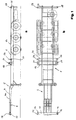
- the crossbar 10 is shown in an enlarged plan view.
- the locking housings 12 at the ends, in which the plug pins 14 are movably mounted in the axial direction.
- the plug pins are shown in their extended position.
- the lock housings serve not only for mounting the plug pins 14, but also for holding twist locks 16 in the vertical direction, while the plug pins 14 extend horizontally and in the longitudinal direction of the container chassis (cf. also FIG. 1b), but counter to the direction of travel.
- the plug pin and the twist lock 16 are arranged in the locking housing 12 so that the central axis of the clamping bolt of the twist lock 16 intersects the central axis of the plug pin 14 at right angles.
- FIGS. 3a and b show a vertical cross section along the line III-III of FIG. 2 and FIG. 3b shows a horizontal longitudinal section.
- the locking housing 12 is hollow and receives a guide part 30 on which the plug pin 14 sits, which projects outwards through an opening 31 in the locking housing 12.
- the guide part 30 is dimensioned and mounted within the hollow locking housing such that it is in the axial direction of the plug pin 14 between a first position in which the plug pin 14 is completely extended from the locking housing 12 (shown in solid lines in FIGS.
- the guide member 30 is with a straight slot or Provide slot 32 through which the clamping bolt 34 of the twist lock 16 extends at right angles to the direction of movement of the guide part 30.
- the diameter of the clamping bolt 34 is only slightly smaller than the width of the elongated hole 32.
- the clamping bolt 34 is stationary in the locking housing 12, but is rotatably mounted.
- the clamping bolt 34 carries at its upper end the locking head 36 of the twist lock 16, which is arranged on the top of the locking housing 12.
- the clamping bolt 34 protrudes from the underside of the locking housing 12 and is provided at its lower end 35 with a clamping nut, not shown in the figures.
- the clamping bolt 34 of the twist lock 16 together with the elongated hole 32 of the guide part 30 receiving it, serves as a guide device which ensures that the plug pin 14 is axially movable but prevents movement in the transverse direction.
- the central axis of the elongated hole 32 coincides with the central axis of the plug pin 14 and is cut at right angles from the central axis of the clamping bolt 34.
- the outer sides of the guide part 30 rest loosely on the facing inner sides of the locking housing 12.
- the guide part 30 has a substantially flat O-shape.
- a small guide pin 38 sits on the upper side of the guide part 30 and is loosely inserted in a recess 40 at one end of a pivot lever 42.
- the pivot lever 42 is held on the crossbar 10 and about an axis of rotation 44 pivotable.
- the pivot lever 42 sits outside the locking housing 12 and projects through an opening 46 into it so that the recess 40 can grip around the pin 38 of the guide part 30 arranged in the locking housing 12 at one end.
- the pivot lever 42 is shown in solid lines in a position in which the plug pin 14 is fully extended, and in dash-dotted lines in a further position in which the plug pin 14 is fully inserted into the locking housing 12.
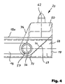
- twist locks 20 at the two ends of the second crossbar 18 is explained in more detail below with reference to FIGS. 4 and 5.
- the twist lock 20 is held in a twist lock housing 50 which has two plate-shaped side legs 51, 52 which are arranged parallel and at a distance from one another and which are connected to one another by a plate-shaped upper part 53 and a rib element 54 arranged below this.
- each twist-lock housing 50 is pivotally supported on the crossbar 18 by means of a pivot pin 56.
- the crossbeam 18 consists of two spaced and parallel to each other cross member, between which the twist lock housing of each of the two twist locks 20 is arranged and pivotally supported.
- the twist-lock housing 50 has a sleeve 58 which connects the two side parts 51, 52 on the inside with one another, as can be seen in FIG. 5b.
- Corresponding holes are provided in the two truss parts through which the ends of the Sleeve 58 received pivot pin 56 for pivoting mounting of the twist lock housing 50 protrude.
- the axis of rotation of the pivot pin 56 runs horizontally and in the direction of travel and transversely to the crossbar 18, so that the twist-lock housing 50 can be pivoted transversely to the direction of travel.
- the rib element 54 has a bore for the rotatable mounting of the clamping bolt 60 of the twist lock 20.
- the upper end of the clamping bolt 60 protrudes from the upper part 53 of the twist lock housing 50 and carries the locking head 62, while the clamping and rotating nuts 64, 66 are arranged below the rib element 54 within the twist lock housing 50.
- a plate-shaped element 68 is fastened between the bore 57 and the outermost end 19 on the inner sides of the two cross member parts.
- This plate-shaped element 19 is provided with an edge 69 which faces the opening 57 and thus the central axis of the container chassis and is inclined such that the lower end of the edge 69 is less distant from the central axis of the container chassis than the upper end has (see FIG. 4).
- the side parts 51, 52 of the twist-lock housing 50 are provided with a corresponding edge 70 which is arranged such that it is essentially flat on the edge 69 of the element in the working position of the twist-lock housing 50 shown in FIG 68 rests.
- the element 68 serves as a stop and support element for holding the twist-lock housing 50 in the working position in which the axis of rotation of the clamping bolt 60 of the twist-lock 20 is directed vertically, so that the locking head 62 projects upwards and the outer surface of the Upper part 53 of the twist lock housing 50 forms a horizontal support surface for a container of the short design.
- the edge 70 of the twist-lock housing 50 rests securely on the edge 69 of the element 68, so that special locking means for locking the twist-lock housing 50 are not absolutely necessary.
- the element 68 has a further edge 72 which faces the central axis of the container chassis and which essentially adjoins the lower end of the inclined edge 69 vertically.
- This edge 72 serves as a stop for the twist-lock housing 50 when it is pivoted into the rest position. In the rest position, the twist-lock housing 50 then lies against this edge 72 with the edge 74 opposite the edge 70, as a result of which further pivoting or oscillation of the twist-lock housing 50 in its rest position is prevented.
- twist-lock housing 50 If the twist-lock housing 50 is now to be brought into its rest position from its working position shown in FIG. 4, it only has to be pivoted downwards in the direction of arrow 76 between the two cross-member parts of the cross-member 18. In the rest position, the twist-lock housing 50 is located completely below the support plane formed by the upper side 18a of the crossbar 18. The swivel angle is a maximum of approximately 180 °.
- twist-lock housings 50 are in the rest position at the ends of the second crossbar 18 pivoted because the container must rest on the top 18a of the second crossbar 18 and the twist locks 20 are not needed in their working position, but then only interfere. If, on the other hand, two containers of the short design are to be used, the twist-lock housings 50 are pivoted in their working position, since the twist-locks 20 are then required to lock the rear of the front container.
- the height of the twist-lock housings 50 are dimensioned such that in the working position the surface of the upper side 53 forms a common support plane with the support surface 4a of the front section 4 of the container chassis 2.
- FIGS. 6 and 7 show further versions of locking housings 12 'and 12' 'which differ from the version shown in FIG. 3 in that a twist lock is not provided and a bolt 80 instead of the twist lock clamping bolt is fastened in the housing 12 'and 12' ', which extends at right angles to the direction of movement of the guide part 30 and thus to the axis of the plug pin 14.
- the diameter of the bolt 80 is only slightly smaller than the width of the elongated hole 32.
- the bolt 80 has a hexagon head at one end and a threaded section at its other end, onto which a nut is screwed in order to secure the bolt 80 in the locking housing 12 'or 12' '.
- the bolt 80 is stationary and fixed in the locking housing 12 'or 12' '.
- FIGS. 6 and 7 differ from the version in FIG. 3 in that the pivot lever 42 is located directly on the locking housing 12 'or 12''is pivotally mounted about its axis of rotation 44.
- a fork bearing 82 is provided on the end face 12a 'of the locking housing 12', on which the pivot lever 42 is pivotably supported with the aid of an articulated bolt 84.
- pivot lever 42 in the embodiment of FIG. 7 is mounted directly in the housing with the aid of the articulation pin 84 between two side walls 12a ′′ and 12b ′′ and protrudes therefrom.
- FIGS. 6 and 7 form separate units from the cross member 10, which are manufactured independently of the cross member 10 and then only have to be attached to the ends of the cross member 10, preferably by welding. This eliminates the need for adjustment work on the cross member, which can sometimes lead to problems with regard to the strength and statics of the cross member.
- the locking housing 12 'shown in Figure 6 is attached with its end face 12a' to the open end of the cross member 10 so that the pivot lever 42 protrudes into the cavity of the cross member 10.
- the pivot lever 42 can then be operated through openings formed in the cross member 10.
- FIGS. 6 and 7 have the same design features as the design of FIG. 3.
- the outside of the guide part 30 lies loosely against the facing inside of the locking housing 12 'or 12' 'and is thus also guided from the inside of the locking housing.
- the pivot lever 42 also has at one end the recess with which it can grip around the pin 38 seated on the guide part 30.
Landscapes
- Engineering & Computer Science (AREA)
- Transportation (AREA)
- Mechanical Engineering (AREA)
- Fittings On The Vehicle Exterior For Carrying Loads, And Devices For Holding Or Mounting Articles (AREA)
- Passenger Equipment (AREA)
Applications Claiming Priority (2)
| Application Number | Priority Date | Filing Date | Title |
|---|---|---|---|
| DE9114903U DE9114903U1 (fr) | 1991-11-30 | 1991-11-30 | |
| DE9114903U | 1991-11-30 |
Publications (2)
| Publication Number | Publication Date |
|---|---|
| EP0545019A1 true EP0545019A1 (fr) | 1993-06-09 |
| EP0545019B1 EP0545019B1 (fr) | 1996-02-14 |
Family
ID=6873794
Family Applications (1)
| Application Number | Title | Priority Date | Filing Date |
|---|---|---|---|
| EP92116807A Expired - Lifetime EP0545019B1 (fr) | 1991-11-30 | 1992-10-01 | Dispositif de verrouillage d'un conteneur sur le châssis d'un véhicule |
Country Status (3)
| Country | Link |
|---|---|
| EP (1) | EP0545019B1 (fr) |
| DE (2) | DE9114903U1 (fr) |
| ES (1) | ES2084233T3 (fr) |
Cited By (1)
| Publication number | Priority date | Publication date | Assignee | Title |
|---|---|---|---|---|
| EP0878352A3 (fr) * | 1997-05-14 | 1999-05-19 | Frank P. Schulz | Dispositif de verrouillage pour un conteneur sur le châssis d'un véhicule |
Families Citing this family (5)
| Publication number | Priority date | Publication date | Assignee | Title |
|---|---|---|---|---|
| DE19603817A1 (de) * | 1996-02-02 | 1997-10-09 | Gerd Schulz | Vorrichtung zur Verriegelung eines Containers an einem Fahrzeugchassis |
| DE102004045665B4 (de) * | 2004-09-18 | 2008-01-31 | Jost-Werke Gmbh & Co. Kg | Querträger zum stirnseitigen Einbau in ein Chassis |
| DE102014218891A1 (de) | 2014-09-19 | 2016-03-24 | Jost-Werke Gmbh | Verriegelungsvorrichtung für Container |
| DE202018107146U1 (de) * | 2018-12-14 | 2020-03-23 | Kögel Trailer GmbH | Containerverriegelung, Frontausschub eines Fahrgestells mit einer solchen Containerverriegelung, Fahrgestell und Verriegelungsanordnung |
| RU203352U1 (ru) * | 2020-12-18 | 2021-04-01 | Общество с ограниченной ответственностью "Торгово-Закупочная Компания ОВК" (ООО "ТЗК "ОВК") | Откидной фитинговый упор |
Citations (4)
| Publication number | Priority date | Publication date | Assignee | Title |
|---|---|---|---|---|
| US3621236A (en) * | 1970-05-15 | 1971-11-16 | Mac Lean Fogg Lock Nut Co | Convertible securement apparatus for securing standard containers and nonstandard cargo on vehicles |
| GB1298035A (en) * | 1970-09-30 | 1972-11-29 | Fruehauf Corp | Trailer chassis |
| EP0051107A1 (fr) * | 1980-10-11 | 1982-05-12 | Gerd Schulz Fahrzeug- und Container-Technik | Dispositif, en particulier pour verrouiller la face frontale de containers |
| DE8910645U1 (fr) * | 1989-09-07 | 1989-10-19 | Maschinenfabriken Bernard Krone Gmbh, 4441 Spelle, De |
-
1991
- 1991-11-30 DE DE9114903U patent/DE9114903U1/de not_active Expired - Lifetime
-
1992
- 1992-10-01 ES ES92116807T patent/ES2084233T3/es not_active Expired - Lifetime
- 1992-10-01 DE DE59205349T patent/DE59205349D1/de not_active Expired - Lifetime
- 1992-10-01 EP EP92116807A patent/EP0545019B1/fr not_active Expired - Lifetime
Patent Citations (4)
| Publication number | Priority date | Publication date | Assignee | Title |
|---|---|---|---|---|
| US3621236A (en) * | 1970-05-15 | 1971-11-16 | Mac Lean Fogg Lock Nut Co | Convertible securement apparatus for securing standard containers and nonstandard cargo on vehicles |
| GB1298035A (en) * | 1970-09-30 | 1972-11-29 | Fruehauf Corp | Trailer chassis |
| EP0051107A1 (fr) * | 1980-10-11 | 1982-05-12 | Gerd Schulz Fahrzeug- und Container-Technik | Dispositif, en particulier pour verrouiller la face frontale de containers |
| DE8910645U1 (fr) * | 1989-09-07 | 1989-10-19 | Maschinenfabriken Bernard Krone Gmbh, 4441 Spelle, De |
Cited By (2)
| Publication number | Priority date | Publication date | Assignee | Title |
|---|---|---|---|---|
| EP0878352A3 (fr) * | 1997-05-14 | 1999-05-19 | Frank P. Schulz | Dispositif de verrouillage pour un conteneur sur le châssis d'un véhicule |
| US6092967A (en) * | 1997-05-14 | 2000-07-25 | Schulz; Frank P. | Lock for containers on a vehicle chassis |
Also Published As
| Publication number | Publication date |
|---|---|
| DE59205349D1 (de) | 1996-03-28 |
| EP0545019B1 (fr) | 1996-02-14 |
| ES2084233T3 (es) | 1996-05-01 |
| DE9114903U1 (fr) | 1993-03-25 |
Similar Documents
| Publication | Publication Date | Title |
|---|---|---|
| EP1700745B1 (fr) | Porte-charge, en particulier porte-bicyclette | |
| DE4229867A1 (de) | Aufbau eines sonnendachs eines selbstfahrenden fahrzeugs und verfahren zur montage desselben | |
| EP3666591B1 (fr) | Verrouillage du récipient, extension avant d'un châssis dotée d'un tel verrouillage du récipient et dispositif de verrouillage | |
| EP1637393B1 (fr) | Montant de montage pour fixer des conteneurs sur des véhicules | |
| EP0132702B1 (fr) | Attelage entre un véhicule tracteur et une remorque en particulier une remorque à essieu unique | |
| DE102005056837B4 (de) | Einrichtung zum Befestigen eines fahrerseitigen Airbagmoduls in einem Fahrzeug | |
| EP0545019B1 (fr) | Dispositif de verrouillage d'un conteneur sur le châssis d'un véhicule | |
| EP3276112B1 (fr) | Dispositif de verrouillage de porte | |
| EP3549417A1 (fr) | Ensemble de bras de levage pour un relevage hydraulic trois points d'un tracteur ou d'un autre engin de travail agricole ainsi que relevage hydraulic trois points | |
| DE3822542A1 (de) | Ladeanhaenger | |
| DE3737651A1 (de) | Vorrichtung fuer eine unterfalt-ladebordwand | |
| EP1232905A2 (fr) | Dispositif de verrouillage d'une charge sur un véhicule et ses composants | |
| DE10047093A1 (de) | Vorrichtung zur Verriegelung eines Containers an einem Fahrzeugchassis | |
| EP0806309A1 (fr) | Barre d'attelage réglable en hauteur pour remorques de véhicule | |
| DE3740028C2 (de) | Straßenfahrzeug | |
| DE10232561A1 (de) | Anordnung zur Halterung unterschiedlicher Container-Typen auf einem Fahrgestell | |
| DE19648158A1 (de) | Wagenheber | |
| EP1384619A1 (fr) | Dispositif de vérouillage universel pour container sur un semi-remorque | |
| EP0361094B1 (fr) | Dispositif auxiliaire pour un tracteur, en particulier un véhicule tout terrain | |
| DE1988891U (de) | Fahrgestell fuer den container-transport. | |
| DE4035636A1 (de) | Fahrzeugkombination | |
| DE102004012483B4 (de) | Kupplungseinrichtung zum Verbinden eines Zugfahrzeuges mit einem Anhänger | |
| DE3531252C2 (fr) | ||
| DE19636186C1 (de) | Manuell längenveränderliche Zugvorrichtung für mehrachsige Anhänger | |
| EP0355577B1 (fr) | Dispositif d'attelage court |
Legal Events
| Date | Code | Title | Description |
|---|---|---|---|
| PUAI | Public reference made under article 153(3) epc to a published international application that has entered the european phase |
Free format text: ORIGINAL CODE: 0009012 |
|
| AK | Designated contracting states |
Kind code of ref document: A1 Designated state(s): BE DE ES FR GB NL |
|
| 17P | Request for examination filed |
Effective date: 19930709 |
|
| 17Q | First examination report despatched |
Effective date: 19941228 |
|
| GRAA | (expected) grant |
Free format text: ORIGINAL CODE: 0009210 |
|
| AK | Designated contracting states |
Kind code of ref document: B1 Designated state(s): BE DE ES FR GB NL |
|
| GBT | Gb: translation of ep patent filed (gb section 77(6)(a)/1977) |
Effective date: 19960212 |
|
| REF | Corresponds to: |
Ref document number: 59205349 Country of ref document: DE Date of ref document: 19960328 |
|
| REG | Reference to a national code |
Ref country code: ES Ref legal event code: FG2A Ref document number: 2084233 Country of ref document: ES Kind code of ref document: T3 |
|
| ET | Fr: translation filed | ||
| PLBE | No opposition filed within time limit |
Free format text: ORIGINAL CODE: 0009261 |
|
| STAA | Information on the status of an ep patent application or granted ep patent |
Free format text: STATUS: NO OPPOSITION FILED WITHIN TIME LIMIT |
|
| 26N | No opposition filed | ||
| REG | Reference to a national code |
Ref country code: GB Ref legal event code: IF02 |
|
| PGFP | Annual fee paid to national office [announced via postgrant information from national office to epo] |
Ref country code: ES Payment date: 20091026 Year of fee payment: 18 Ref country code: DE Payment date: 20091106 Year of fee payment: 18 |
|
| PGFP | Annual fee paid to national office [announced via postgrant information from national office to epo] |
Ref country code: NL Payment date: 20091027 Year of fee payment: 18 |
|
| PGFP | Annual fee paid to national office [announced via postgrant information from national office to epo] |
Ref country code: FR Payment date: 20091110 Year of fee payment: 18 Ref country code: GB Payment date: 20091023 Year of fee payment: 18 |
|
| PGFP | Annual fee paid to national office [announced via postgrant information from national office to epo] |
Ref country code: BE Payment date: 20091029 Year of fee payment: 18 |
|
| BERE | Be: lapsed |
Owner name: *SCHULZ GERD Effective date: 20101031 |
|
| REG | Reference to a national code |
Ref country code: NL Ref legal event code: V1 Effective date: 20110501 |
|
| GBPC | Gb: european patent ceased through non-payment of renewal fee |
Effective date: 20101001 |
|
| PG25 | Lapsed in a contracting state [announced via postgrant information from national office to epo] |
Ref country code: FR Free format text: LAPSE BECAUSE OF NON-PAYMENT OF DUE FEES Effective date: 20101102 |
|
| REG | Reference to a national code |
Ref country code: FR Ref legal event code: ST Effective date: 20110630 |
|
| REG | Reference to a national code |
Ref country code: DE Ref legal event code: R119 Ref document number: 59205349 Country of ref document: DE Effective date: 20110502 |
|
| PG25 | Lapsed in a contracting state [announced via postgrant information from national office to epo] |
Ref country code: BE Free format text: LAPSE BECAUSE OF NON-PAYMENT OF DUE FEES Effective date: 20101031 Ref country code: NL Free format text: LAPSE BECAUSE OF NON-PAYMENT OF DUE FEES Effective date: 20110501 Ref country code: GB Free format text: LAPSE BECAUSE OF NON-PAYMENT OF DUE FEES Effective date: 20101001 |
|
| REG | Reference to a national code |
Ref country code: ES Ref legal event code: FD2A Effective date: 20111118 |
|
| PG25 | Lapsed in a contracting state [announced via postgrant information from national office to epo] |
Ref country code: ES Free format text: LAPSE BECAUSE OF NON-PAYMENT OF DUE FEES Effective date: 20101002 |
|
| PG25 | Lapsed in a contracting state [announced via postgrant information from national office to epo] |
Ref country code: DE Free format text: LAPSE BECAUSE OF NON-PAYMENT OF DUE FEES Effective date: 20110502 |