EP0544798B1 - Beutelfülleinrichtung mit vertikalschnecke, schwingtrichter, nach unten offenem aubsaugkonus und rotierendem rührflügel - Google Patents
Beutelfülleinrichtung mit vertikalschnecke, schwingtrichter, nach unten offenem aubsaugkonus und rotierendem rührflügel Download PDFInfo
- Publication number
- EP0544798B1 EP0544798B1 EP91915930A EP91915930A EP0544798B1 EP 0544798 B1 EP0544798 B1 EP 0544798B1 EP 91915930 A EP91915930 A EP 91915930A EP 91915930 A EP91915930 A EP 91915930A EP 0544798 B1 EP0544798 B1 EP 0544798B1
- Authority
- EP
- European Patent Office
- Prior art keywords
- auger
- assembly
- bowl
- agitator
- fill tube
- Prior art date
- Legal status (The legal status is an assumption and is not a legal conclusion. Google has not performed a legal analysis and makes no representation as to the accuracy of the status listed.)
- Expired - Lifetime
Links
- 238000013022 venting Methods 0.000 title claims abstract description 23
- 239000000945 filler Substances 0.000 title description 2
- 230000002093 peripheral effect Effects 0.000 claims description 39
- 230000000712 assembly Effects 0.000 claims description 12
- 238000000429 assembly Methods 0.000 claims description 12
- 238000006073 displacement reaction Methods 0.000 claims description 9
- 239000007789 gas Substances 0.000 claims description 7
- 230000033001 locomotion Effects 0.000 claims description 4
- 230000005540 biological transmission Effects 0.000 claims description 2
- 230000013011 mating Effects 0.000 claims description 2
- 230000007246 mechanism Effects 0.000 abstract description 15
- 238000007789 sealing Methods 0.000 abstract description 4
- 238000005303 weighing Methods 0.000 abstract description 4
- 238000013461 design Methods 0.000 description 6
- 230000009977 dual effect Effects 0.000 description 5
- 230000010355 oscillation Effects 0.000 description 3
- VYPSYNLAJGMNEJ-UHFFFAOYSA-N Silicium dioxide Chemical compound O=[Si]=O VYPSYNLAJGMNEJ-UHFFFAOYSA-N 0.000 description 2
- 238000005273 aeration Methods 0.000 description 2
- 239000003638 chemical reducing agent Substances 0.000 description 2
- 230000000694 effects Effects 0.000 description 2
- 239000002184 metal Substances 0.000 description 2
- 238000000034 method Methods 0.000 description 2
- 229920000642 polymer Polymers 0.000 description 2
- 230000008569 process Effects 0.000 description 2
- 238000012545 processing Methods 0.000 description 2
- 239000000725 suspension Substances 0.000 description 2
- 230000006978 adaptation Effects 0.000 description 1
- 239000000853 adhesive Substances 0.000 description 1
- 230000001070 adhesive effect Effects 0.000 description 1
- 238000007796 conventional method Methods 0.000 description 1
- 230000005574 cross-species transmission Effects 0.000 description 1
- 238000005429 filling process Methods 0.000 description 1
- 235000013312 flour Nutrition 0.000 description 1
- 238000009413 insulation Methods 0.000 description 1
- 239000000843 powder Substances 0.000 description 1
- 230000004044 response Effects 0.000 description 1
- 239000000377 silicon dioxide Substances 0.000 description 1
- 230000032258 transport Effects 0.000 description 1
- 238000011179 visual inspection Methods 0.000 description 1
Images


Classifications
-
- B—PERFORMING OPERATIONS; TRANSPORTING
- B65—CONVEYING; PACKING; STORING; HANDLING THIN OR FILAMENTARY MATERIAL
- B65B—MACHINES, APPARATUS OR DEVICES FOR, OR METHODS OF, PACKAGING ARTICLES OR MATERIALS; UNPACKING
- B65B37/00—Supplying or feeding fluent-solid, plastic, or liquid material, or loose masses of small articles, to be packaged
-
- B—PERFORMING OPERATIONS; TRANSPORTING
- B65—CONVEYING; PACKING; STORING; HANDLING THIN OR FILAMENTARY MATERIAL
- B65B—MACHINES, APPARATUS OR DEVICES FOR, OR METHODS OF, PACKAGING ARTICLES OR MATERIALS; UNPACKING
- B65B1/00—Packaging fluent solid material, e.g. powders, granular or loose fibrous material, loose masses of small articles, in individual containers or receptacles, e.g. bags, sacks, boxes, cartons, cans, or jars
- B65B1/04—Methods of, or means for, filling the material into the containers or receptacles
- B65B1/08—Methods of, or means for, filling the material into the containers or receptacles by vibratory feeders
-
- B—PERFORMING OPERATIONS; TRANSPORTING
- B65—CONVEYING; PACKING; STORING; HANDLING THIN OR FILAMENTARY MATERIAL
- B65B—MACHINES, APPARATUS OR DEVICES FOR, OR METHODS OF, PACKAGING ARTICLES OR MATERIALS; UNPACKING
- B65B1/00—Packaging fluent solid material, e.g. powders, granular or loose fibrous material, loose masses of small articles, in individual containers or receptacles, e.g. bags, sacks, boxes, cartons, cans, or jars
- B65B1/04—Methods of, or means for, filling the material into the containers or receptacles
- B65B1/10—Methods of, or means for, filling the material into the containers or receptacles by rotary feeders
- B65B1/12—Methods of, or means for, filling the material into the containers or receptacles by rotary feeders of screw type
-
- B—PERFORMING OPERATIONS; TRANSPORTING
- B65—CONVEYING; PACKING; STORING; HANDLING THIN OR FILAMENTARY MATERIAL
- B65D—CONTAINERS FOR STORAGE OR TRANSPORT OF ARTICLES OR MATERIALS, e.g. BAGS, BARRELS, BOTTLES, BOXES, CANS, CARTONS, CRATES, DRUMS, JARS, TANKS, HOPPERS, FORWARDING CONTAINERS; ACCESSORIES, CLOSURES, OR FITTINGS THEREFOR; PACKAGING ELEMENTS; PACKAGES
- B65D88/00—Large containers
- B65D88/54—Large containers characterised by means facilitating filling or emptying
- B65D88/64—Large containers characterised by means facilitating filling or emptying preventing bridge formation
- B65D88/68—Large containers characterised by means facilitating filling or emptying preventing bridge formation using rotating devices
-
- B—PERFORMING OPERATIONS; TRANSPORTING
- B65—CONVEYING; PACKING; STORING; HANDLING THIN OR FILAMENTARY MATERIAL
- B65G—TRANSPORT OR STORAGE DEVICES, e.g. CONVEYORS FOR LOADING OR TIPPING, SHOP CONVEYOR SYSTEMS OR PNEUMATIC TUBE CONVEYORS
- B65G65/00—Loading or unloading
- B65G65/30—Methods or devices for filling or emptying bunkers, hoppers, tanks, or like containers, of interest apart from their use in particular chemical or physical processes or their application in particular machines, e.g. not covered by a single other subclass
- B65G65/34—Emptying devices
- B65G65/40—Devices for emptying otherwise than from the top
- B65G65/46—Devices for emptying otherwise than from the top using screw conveyors
- B65G65/463—Devices for emptying otherwise than from the top using screw conveyors arranged vertically or substantially vertically within the container
Definitions
- This invention relates generally to vertical auger or vertical screw type bag filling machines for filling products into bags, and particularly to a vertical auger type bag filler having a vibrating bowl, inverted venting cone, and a rotating agitator assembly.
- US-A-4 944 334 discloses a vibrating hopper with inverted venting cone in accordance with the pre-characterising portion of claim 1, which apparatus is connected to a vertical auger bag filling machine via a cross auger conveyor.
- This system has proven effective for de-aerating and filling many types of powdered and granular products that were previously, at best, difficult to de-aerate and fill.
- the system provides great adaptability to handling different types of products through adjustments and fine tuning of the various elements along the system, and provides for adjustment of those components.
- Model 3CM-F Automatic Bagging Machine by the Newlong Machine Works, Ltd. of Tokyo, Japan (American-NewLong Inc., Indianapolis, Indiana) incorporates a vibrating hopper and a two vertical screw feeds which may be adapted between a standard configuration and a specialized configuration for extremely fine powdered products.
- the Newlong system utilizes a service hopper which feeds product into a vibratile hopper.
- the vibratile hopper is disposed above a conical primary fill hopper having a fill tube and screw feeder with a bag elevator mechanism which permits bottom filling of bags.
- the bags are lowered by the bag elevator mechanism when the filling process commences, with the filling cycle being controlled by a timer that interrupts rotation of the screw feeder after a pre-set time.
- the bag top is shaped and the bag is then forwarded to a secondary fill station which is also disposed beneath the vibratile hopper.
- the bag is supported from above on a load-cell weight scale, and a secondary screw feeder fills the bag with the balance of a pre-set weight of product.
- the bag is then transferred via a conveyor to a bag inserter and bag top slitter, and the top of the bag is then sealed using a heat sealer or stitching machine.
- hoppers or bowls are required to accomplish both the vibrational de-aeration process and the independent primary filling and secondary topping processes, with at least three of those hoppers or bowls being disposed in generally vertical alignment. Including the height of the fill tubes and conduits connecting the hoppers or bowls, the system then requires significant minimum interior ceiling height for clearance.
- the system requires two outlet ports from the vibratile hopper, thus preventing effective use of auxiliary equipment within the vibratile hopper such as an inverted venting cone, vertical auger, or an agitator assembly. Since the bag is transferred between a primary fill station and a topping station with correctional weighing commencing after the bag reaches the topping station, there is a significant delay in processing bags through the system.
- the system requires two independent sets of screw feeder drives for the separate filling stations, and if the system is adapted for automated responsive filling, two sets of controls for measuring product density within the two fill tubes and adjusting the revolutions of the two screw feeders are necessary.
- the system for filling extremely fine powders is distinct from the standard arrangement, and tuning either system for different types of products can only be accomplished by synchronizing several system elements.
- auger bowl may be equipped with an venting device such as an inverted venting cone.
- the present invention provides a container filling machine for filling a product into a container, said container filling machine comprising:
- a preferred vertical auger bottom-fill bag filling machine includes a conical auger bowl depending from a cylindrical hopper on rocker arms, with the auger bowl being connected to the cylindrical hopper and a fill tube by flexible gaskets.
- a vertical auger shaft extends through the cylindrical hopper, auger bowl, and fill tube, with a section of flighting disposed within the auger bowl and fill tube to compress, de-aerate, and dispense the product.
- An agitator is mounted on the bottom of an agitator drive shaft which circumscribes the auger shaft and rotates independent thereof, the agitator having paddles which moves the product and press the product downwardly in the auger bowl.
- An inverted venting cone is disposed within the auger bowl, with a vent tube extending upwardly and terminating proximate to the top of the cylindrical hopper.
- the inverted venting cone and vent tube are connected to the auger bowl to vibrate therewith, the vent tube surrounding and being spaced apart from the auger shaft and agitator drive shaft.
- the fill tube includes an enlarged upper section which permits the auger bowl to vibrate even though the diameters of the section of flighting and lower section of the fill tube are closely fitted.
- the vertical auger bottom-fill bag filling machine is incorporated into an automated bag filling system including a bag magazine, bag pickup and hanging mechanism, bag elevator assembly, bag weighing mechanism, bag conveyor, sealing station, and associated controls.
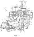
- FIG. 1-11 A vertical auger bottom-fill bag filling machine constructed in accordance with the present invention is shown in Figures 1-11 and referenced generally therein by the numeral 10.
- the vertical auger bottom-fill bag filling machine 10 is incorporated into an automated bag filling system 12.
- the vertical auger bottom-fill bag filling machine 10 is mounted within a frame assembly 14 including an access ladder 16 and an upper deck 18 and a railing 20 surrounding the vertical auger bottom-fill bug filling machine 10.
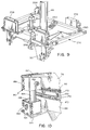
- An empty bag 22 is transferred by a bag input conveyor 24 from a conventional bag magazine (not shown) to a position proximate to the vertical auger bottom-fill bag filling machine 10, and is grasped by the bag gripping members 26 of the bag pickup and hanging mechanism 28 which pivot upwardly and mount the bag 22 on a clam-jaw fill spout 30 as shown in Figure 8.
- the fill spout 30 is mounted on a pair of generally horizontal carrier plates 32, 34, the lower plate 34 being pivoted downward by a dual acting power cylinder 36 across a hinge 38 extending along the edges of the carrier plates 32, 34 opposite the power cylinder 36.
- the fill spout 30 is pivoted toward the bag conveyor 24 and bag pickup and hanging mechanism 28 to permit the bag 22 to be mounted on the fill spout 30.
- the bag 22 is held in place on the fill spout 30 by two pair of bag holding members 40 which grip and hold the top gusset of the bag 22 on opposing sides of the fill spout 30, and are pivoted by dual acting power cylinders 42.
- the central portion of the top of each bag 22 is held against the fill spout 30 by a pair of clamping assemblies 44 which are each similarly pivoted by a dual acting power cylinder 46 mounted on or adjacent to the fill spout 30.
- the bag pickup and hanging mechanism 28, fill spout 30, horizontal carrier plates 32, 34, bag holding members 40, and clamping assemblies 44 are carried in the vertical direction by a bag elevator assembly 48 of a conventional type, which may also include a pair of dual acting power cylinders 50, 52 which permit continuous settling of the product 54 filled into the bag 22 using an oscillating bag settling arm 56 which travels with the bag 22 as the bag 22 is raised and lowered along a generally vertical path during the bag hanging and filling cycle.
- Filled bags 22 are lowered by the bag elevator assembly 48 onto a conveyor belt assembly 58 including a dual track conveyor 60 disposed beneath the fill spout 30 and an extended conveyor belt 62 driven by a motor assembly 64.
- the conveyor belt 62 transports the bag 22 to or through a bag folding machine 66 and sealing station 68 which fold the open tops of the bags 22 and seal the bags 22 using conventional techniques such as stitching, adhesive, or a heat seal.
- the operation of the vertical auger bottom-fill bag filling machine 10, bag elevator assembly 48, bag pickup and hanging mechanism 28, conveyor belt assembly 58, bag folding machine 66 and bag sealing station 68 are coordinated by a central processing unit (CPU) 70 which receives signals from various sensors and load cells disposed on those components, and which may be manually operated, interrupted, reset, or monitored via a control panel 72.
- CPU central processing unit
- a safety shield 74 permits visual inspection of the operation of the vertical auger bottom-fill bag filling machine 10, bag elevator assembly 48, and bag pickup and hanging mechanism 28 throughout the bag hanging and filling cycle during operation of the vertical auger bottom-fill bag filling machine 10.
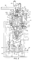
- the vertical auger bottom-fill bag filling machine 10 may be seen to comprise a generally cylindrical hopper 76 which is fixedly attached and mounted to the frame assembly 14 at or slightly above the height of the deck 18.
- the hopper 76 includes a generally circular lid 78 which covers and seals the open top of hopper 76.
- Product 54 is dispensed into the hopper 76 through an inlet tube 80 connected to and communicating with an aperture or inlet port in the lid 78, the inlet tube 80 being connected to a cross auger 82 or other mechanism for conveying product 54 to the hopper 76 from a replenishable source or supply (not shown).
- air pressure is vented through an air outlet or venting port 84 in the top of the cross auger 82.
- air pressure is vented through an air outlet or venting port 86 connected to and communicating with an aperture or outlet in the lid 78 of the hopper 76.
- a conical auger bowl 88 is suspended beneath the hopper 76 on a plurality of pivotal connecting rod assemblies 90.
- a fill tube assembly 92 is connected to the bottom of the auger bowl 88 and is composed of an outlet or neck region 94 of the auger bowl 88, an upper fill tube segment 96 or reducer fitting, and a lower fill tube segment 98 which are aligned and communicate with one another.
- the hopper 76 is spaced apart above and connected to the top of the auger bowl 88 by a flexible gasket or resilient connector 100.
- the upper fill tube segment 96 is spaced apart beneath and connected to the bottom of the neck region 94 of the auger bowl 88 by a similar but smaller diameter flexible gasket or resilient connector 102.
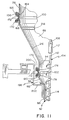
- a multi-stage auger shaft 104 extends downwardly through the hopper 76 and auger bowl 88 from a point disposed above the lid 78 to the distal end 106 of the lower fill tube segment 98.
- the auger shaft 104 is composed of an upper shaft segment 108 and a lower shaft segment 110 connected by a coupler 112, the lower shaft segment 110 including a section of flighting 114 or helical screw blades which compress product 54 within the fill tube assembly 92 and dispense product 54 from the distal end 106 into the bag 22.
- the upper shaft segment 108 and lower shaft segment 110 are interlocked together by the coupler 112 and connected thereto using a plurality of threaded fasteners 116 or similar conventional securing devices.
- the top end of the auger shaft 104 extends upwardly through the lid 78 of the hopper 76 and is connected to a shaft drive assembly 118.
- the drive assembly 118 includes a high torque, variable speed DC drive motor 120 having an upwardly extending motor shaft 122 and geared drive wheel 124 connected thereto.
- a geared drive belt 126 meshes with the drive wheel 122 and is mounted thereon, and extends horizontally to a second geared drive wheel 128 mounted at the lower end of an intermediate drive axle 130.
- a pneumatic clutch 132 is connected to the bottom of the intermediate drive axle 130, and to a source of gas pressure which is controlled by the CPU 70.
- the pneumatic clutch 132 may be used to selectively or responsively control the rate and direction of rotation of the intermediate drive axle 130, or to completely disengage the intermediate drive axle 130.
- a third drive wheel 134 is connected to the top end of the intermediate drive axle 130.
- a second geared drive belt 136 meshes with and is mounted on the third geared drive wheel 134 and extends horizontally to a fourth geared drive wheel 138 connected to the top of a second intermediate drive axle 140.
- a second pneumatic clutch 142 is disposed between and connected to the lower end of the second intermediate drive axle 140 and the top end of the upper auger shaft 108, and may be used to selectively or responsively control the rate and direction of rotation of the upper shaft segment 108 and auger shaft assembly 104, or to completely disengage the auger shaft assembly 104. It is understood that any suitable type of a transmission means, such as a direct drive servo motor, may be utilized in place of the clutches 132, 142 in particular applications.
- a vibrator assembly 144 or vibration producing means is connected to the auger bowl 88.
- the vibrator assembly 144 includes a drive motor 146 such as a DC electric motor having a drive shaft 148 and a first geared drive wheel 150 mounted thereon, with a geared drive belt 152 extending from the first drive wheel 150 to a second geared drive wheel 154 mounted on the upper end of a weight shaft 156.
- the weight shaft 156 extends vertically through and is mounted for rotation within a weight housing 158, the weight housing 158 being fixedly connected to the outer surface of the auger bowl 88.
- a plurality of counterweights 160 are mounted such that the center of mass of the combined counterweights 160 is linearly displaced or offset from the axis of rotation of the weight shaft 156, such that when the weight shaft 156 and counterweights 160 are rotated at sufficient angular velocity, the weight shaft 156 and counterweights 160 will induce oscillations or vibrations which are transmitted from the weight shaft 156 through one or more bearing assemblies 162 to the weight housing 158, and in turn to the auger bowl 88.
- the number and position of the counterweights 160 may be manually adjusted so that the total mass and degrees of linear displacement of the center of mass of the counterweights 160 relative to the axis of rotation of the weight shaft 156 may be selectively determined, and the angular velocity of the weight shaft 156 and counterweights 160 may be monitored by the CPU 70 and the magnitude and rate of the oscillations or vibrations controlled by adjusting the speed of the drive motor 146.
- the flexible connectors 100, 102 disposed between the auger bowl 88 and the hopper 76 and fill tube assembly 92 insulate the hopper 76 and fill tube assembly 92 from the vibration of the auger bowl 88 so that the auger bowl 88 moves horizontally and vibrates independently of the hopper 76, fill tube assembly 92, or frame assembly 14.
- the upper flexible connector 100 extends around and contacts the outer surface of the bottom peripheral edge 164 of the hopper 76 beneath an outwardly extending flange member 166, and extends around and contacts the outer surface of the top peripheral edge 168 of the auger bowl 88 above an outwardly extending flange member 170.
- the upper flexible connector 100 is clamped or secured in place in engaging contact with the outer surface of the bottom peripheral edge 164 of the hopper 76 and the outer surface of the top peripheral edge 168 of the auger bowl 88 by a pair of metal or polymer bands 172 which are cinched or tightened sufficiently to prevent the flexible connector 100 from leaking product 54 or sliding off the bottom peripheral edge 164 of the hopper 76 and top peripheral edge 168 of the auger bowl 88 when the auger bowl 88 is vibrated vigorously over an extended period of time.
- the lower flexible connector 102 extends around and contacts the outer surface of the bottom peripheral edge 174 of the neck region 94 of the auger bowl 88 beneath an outwardly extending flange member 176, and extends around and contacts the outer surface of the top peripheral edge 178 of the upper fill tube segment 96 above an outwardly extending flange member 180.
- the lower flexible connector 102 is clamped or secured in place in engaging contact with the outer surface of the bottom peripheral edge 174 of the neck region 94 and the outer surface of the top peripheral edge 178 of the upper fill tube segment 96 by a pair of smaller diameter metal or polymer bands (not shown) which are cinched or tightened sufficient to prevent the flexible connector 102 from leaking product 54 or sliding off the bottom peripheral edge 174 of the neck region 94 and top peripheral edge 178 of the upper fill tube segment 96 during vibration of the auger bowl 88.
- the upper fill tube segment 96 or reducer fitting has a tapered central portion, the top peripheral edge 178 having a diameter greater than the diameter of the bottom peripheral edge 182 where the upper fill tube segment 96 is joined to the lower fill tube segment 98, the bottom peripheral edge 182 having a diameter substantially equal to the diameter of the lower fill tube segment 98.
- the inside diameters of the bottom peripheral edge 182 and lower fill tube segment 98 are generally equal to the outer diameter of the section of flighting 114 within tolerances necessary to permit the section of flighting 114 to convey all or substantially all of the product 54 within the lower fill tube segment 98 without appreciable overflighting or spill-over around the edges of the section of flighting 114.
- the respective diameters of the lower fill tube segment 98 and the section of flighting 114 may be considered approximately equal to one another even though a gap or space between the lower fill tube segment 98 and section of flighting 114 is intentionally maintained to permit a predetermined amount of overflighting to occur, whereby product 54 will pass over the edge of the section of flighting 114 between the section of flighting 114 and the inner surface of the lower fill tube segment 98.
- the diameter of the top peripheral edge 178 of the upper fill tube segment 96 is generally equal to the diameter of the bottom peripheral edge 174 of the neck region 94 of the auger bowl 88 so that the respective top peripheral edge 178 and bottom peripheral edge 174 will be aligned with one another when the auger bowl 88 is at rest of not being vibrated.
- the diameter of the top peripheral edge 178 and bottom peripheral edge 174 are sufficient so that the auger bowl 88 may be vibrated in a generally horizontal plane perpendicular to the axis of rotation of the auger shaft assembly 104 without the neck region 94 and flexible connector 102 contacting the outer edge of the section of flighting 114.
- the diameter of the bottom peripheral edge 174 of the neck region 94 should be at least equal to or greater than two times the maximum linear displacement of the auger bowl 88 relative to the centerline or axis of rotation of the lower shaft section 110 of the vertical auger shaft assembly 104 plus the maximum outer diameter of the section of flighting 114 in the proximity of the neck region 94 (or one times the total maximum linear displacement of the auger bowl 88 relative to the centerline or axis of rotation of the lower shaft section 110 if that total maximum linear displacement is considered to be the sum of the linear displacements in two diametrically opposing directions relative to the axis of rotation of the lower shaft section 110.)
- the connecting rod assemblies 90 are each comprised of a rocker arm 184 having a generally cylindrical fitting 186 fixedly attached to each opposing end of the rocker arm 184.
- Each of the two cylindrical fittings 186 attached to the rocker arm 184 defines a cylindrical bore (not shown), the two cylindrical bores and cylindrical fittings 186 of each rocker arm 184 being oriented generally orthogonal to one another and to a vertical centerline of the rocker arm 184 when the rocker arm 184 depends or hangs in a vertical position.
- Each cylindrical fitting 186 is received and disposed within an upper or lower box-like housing 188, 190 having an open bottom or top end, respectively, with the upper housing 188 being fixedly connected to a bracket 192 which is in turn fixedly connected to the outer surface of the hopper 76, and the lower housing 190 being fixedly connected to a bracket 194 which is in turn fixedly connected to the outer surface of the auger bowl 88.
- a first threaded fastener 196 extends completely through the cylindrical bore of the upper cylindrical fitting 186 and through a pair of apertures defined by the opposing sides of the upper housing 188 normal to the outer surface of the hopper 76, the first threaded fastener 196 serving as an axle permitting the lower portion of the rocker arm 184 to pivot inwardly and outwardly or toward and away from the outer surface of the auger bowl 88 generally normal thereto.
- a second threaded fastener 196 extends completely through the cylindrical bore of the lower cylindrical fitting 186 and through a pair of apertures defined by the inner and outer sides of the lower housing 190 parallel with the outer surface of the auger bowl 88, the second threaded fastener 196 serving as an axle permitting the upper portion of the rocker arm 184 to pivot back and forth along the outer surface of the hopper 76 generally parallel therewith.
- the fill tube assembly 92 is mounted on a suspension bracket 198 which is fixedly attached to the frame assembly 114 on opposing sides of and at approximately the same height as the upper fill tube segment 96.
- the suspension bracket 198 includes two inverted L-shaped segments 200 which extend inwardly and downwardly from the frame assembly 14. The lower edges of the inverted L-shaped segments 200 are connected by a central segment 202 to which the upper fill tube segment 96 and lower fill tube segment 98 are connected, the central segment 200 defining an aperture through which the lower fill tube segment 98 depends.
- the vertical auger bottom-fill bag filling machine 10 includes a venting assembly 204 disposed within the hopper 76.
- the venting assembly 204 comprises a truncated cone 206 which defines an open top aperture 208 and a peripheral bottom edge 210 and a vent tube 212, or a similar flow passage means to vent gases de-aerated from the product 54 within the auger bowl 88 to the exterior of the auger bowl 88 or to the top of the hopper 76.
- the vertical vent tube 212 is fixedly connected to the top of the truncated cone 206 and extends upwardly therefrom and terminates at a top end 214 or vent discharge disposed beneath the lid 78 of the hopper 76.
- the vent tube 212 has a diameter equal to the open top aperture 208, and is aligned and communicates therewith such that air or gas de-aerated from the product 54 within the hopper 76 at a point below the peripheral bottom edge 210 of the truncated cone 206 will pass upwardly through the vent tube 212. It should be understood that the vent tube 212 or flow passage means may be designed to extend radially outward to or through the side of the hopper 76, in which case the gases de-aerated from the product 54 will be vented outwardly rather than or as well as upwardly.
- the truncated cone 206 is connected to the inner surface 216 of the auger bowl 88 by a plurality of brace members 218 which are fixedly connected to the outer top angled surface of the truncated cone 206 and the inner surface 216 of the auger bowl 88. Consequently, the venting assembly 204 is completely supported by and carried with the auger bowl 88, and vibrates linearly back and forth therewith when the vibrator assembly 144 vibrates the auger bowl 88.
- the vertical auger bottom-fill bag filling machine 10 also includes an agitator assembly 220 which extends from a point above the lid 78 of the hopper 76 to a position within the auger bowl 88 beneath the peripheral bottom edge 210 of the truncated cone 206.
- the agitator assembly 220 comprises a hollow cylindrical agitator drive shaft 222 disposed within the vent tube 212 and defining a longitudinal bore receiving the auger shaft assembly 104 such that the agitator drive shaft circumscribes the upper shaft segment 108.
- the agitator drive shaft 222 is carried on and rotates independently of the upper shaft segment 108 on a plurality of bearing assemblies 224 which maintain the agitator drive shaft 222 in a generally vertical orientation aligned with the upper shaft segment 108.
- the agitator drive shaft 222 is spaced apart from vent tube 212 on all sides a distance sufficient to permit the maximum amplitude in vibration or oscillation of the vent tube 212 and truncated cone 206 without contacting the outer surface of the agitator drive shaft 222, thereby also permitting air or gas de-aerated from the product 54 within the auger bowl 88 to be vented upwardly through the vent tube 212 between the agitator drive shaft 222 and the vent tube 212.
- An agitator mounting collar 226 is removably connected to and interlocked with the bottom end of agitator drive shaft 222.
- the agitator mounting collar 226 consists of a pair of mating semi-annular collar segments 228, 230, each collar segment 228, 230 extending partially around the agitator drive shaft 222 and having a pair of generally vertical flange members 232 which abuttingly contact the flange members 234 of the opposing collar segment 230, 228 respectively.
- the two collar segments 228, 230 are fastened together using a plurality of threaded fasteners 236 which extend through the flange members 232, 234 or a similar fastening or securing means, with the assembled mounting collar 226 being fastened to the agitator drive shaft 222 using a plurality of threaded fasteners 238 or a similar fastening or securing means.
- each agitator mounting bracket 240 Extending from and fixedly connected to each of the collar segments 228, 230 on diametrically opposing sides of the mounting collar 226 is a agitator mounting bracket 240, each agitator mounting bracket 240 having a generally inverted U-shape and defining a channel 242 therein.
- a pair of agitator paddle assemblies 244 are removably mounted to the agitator mounting brackets 240.
- the agitator paddle assemblies 244 each include a generally horizontal mounting plate 246 dimensioned to be received within the channel 242 of the corresponding agitator mounting bracket 240 and connected thereto using a plurality of threaded fasteners 248 or a similar fastening or securing means, an outwardly angled paddle shaft 250 fixedly connected to and depending from the mounting plate 246, and a paddle member 252.
- the paddle shafts 250 are each sized and angled such that the opposing paddle shafts 250 and paddle members 252 are generally symmetrical to one another, with the paddle members 252 extending generally parallel with the inner surface of the auger bowl 88 and spaced apart therefrom sufficiently that the paddle members 252 do not contact the auger bowl 88 when the auger bowl 88 is vibrated.
- Each paddle member 252 is shaped and oriented to move and de-aerate the product 54 within the auger bowl 88, and to press the product 54 downwardly and inwardly within the auger bowl 88 toward the neck region 94 and section of flighting 114
- the horizontal carrier plates 32, 34 define a central opening 254 through which the lower fill tube segment 98 extends toward the fill spout 30 mounted thereunder.
- Figure 9 shows an alternative embodiment with the carrier plates 32, 34 being disposed within a rectangular frame 256, with the rectangular frame being supported on a plurality of load cells 258.
- Each load cell 258 includes a contact 260 which is engaged when the lower carrier plate 34 is pivoted upwardly to parallel with the upper carrier plate 32.
- the rectangular frame 256 is connected to the bag elevator assembly 48 and travels therewith, the load cells 258 being capable of continuously measuring the weight of the hanging bag 22 and product 54 within the bag 22 after taring the measured weight of any suspended portion of the rectangular frame 256, carrier plates 32, 34, bag pickup and hanging mechanism 28, fill spout 30, bag holding members 40, and clamping assemblies 44.
- a separate agitator drive motor 262 is mounted to the frame assembly 14 or lid 78 of the hopper 76, with the agitator drive motor 262 being connected to the top of the agitator drive shaft 222 via a differential 264, first drive gear 266, endless chain 268, and second drive gear 270 mounted on the agitator drive shaft 222.
- the agitator drive motor 262 may be a conventional variable speed DC electric motor, and may include a pickoff (not shown) or other timing or synchronization device electronically coupled to the CPU 70 such that the direction of rotation and angular velocity of the agitator paddles 252 may be monitored and adjusted either selectively or in response to the condition of the product 54 within the auger bowl 88 or fill tube assembly 92.
Landscapes
- Engineering & Computer Science (AREA)
- Mechanical Engineering (AREA)
- Basic Packing Technique (AREA)
- Supply Of Fluid Materials To The Packaging Location (AREA)
Claims (21)
- Behälterfüllmaschine (10) für das Abfüllen eines Produkts in einen Behälter, welche Behälterfüllmaschine umfaßt:einen Trichter (76) mit einer Oberseite, einem unteren peripheren Rand (164) und einer inneren Region zur Aufnahme des Produkts;eine Schneckenschüssel (88), welche Schneckenschüssel mit dem Trichter (76) nahe dem unteren peripheren Rand (164) desselben verbunden ist und sich generell unter ihm befindet, derart, daß das Produkt innerhalb des Trichters nach unten in die Schneckenschüssel (88) transferiert werden kann, welche Schneckenschüssel einen Innenraum und einen Auslaß (94) aufweist, durch den das Produkt von der Schneckenschüssel transferiert wird;eine Vibratorbaugruppe (144), die in Wirkverbindung mit der Schneckenschüssel (88) steht und die Schneckenschüssel selektiv zum Vibrieren bringen kann;eine Schneckenwellenbaugruppe (104), welche Schneckenwellenbaugruppe in einer generell vertikalen Richtung orientiert ist und sich von einem oberen Ende nahe oder oberhalb der inneren Region des Trichters (76) zu einem unteren Ende erstreckt, welche Schneckenwellenbaugruppe (104) drehbeweglich um eine Drehachse montiert ist, die in generell vertikaler Richtung orientiert ist, welche Schneckenwellenbaugruppe ferner einen Schneckengangabschnitt (114) aufweist; undeine Belüftungsbaugruppe (204), die mindestens teilweise innerhalb des Trichters (76) und der Schneckenschüssel (88) angeordnet ist, welche Belüftungsbaugruppe ein Strömungspassagemittel (212) aufweist, das zwischen dem Inneren der Schneckenschüssel und einem Belüftungsaustrag für die Abfuhr von Gasen kommuniziert, die von dem Produkt innerhalb der Schneckenschüssel entgast werden, welches Strömungspassagemittel (212) generell zumindest einen Abschnitt der Schneckenwellenbaugruppe (104) umschreibt und ein Belüftungsrohr (212) umfaßt,
dadurch gekennzeichnet, daß die Maschine (10) ferner umfaßt:eine Agitatorbaugruppe (220), die mindestens teilweise innerhalb der Schneckenschüssel (88) angeordnet ist, wobei zumindest ein Abschnitt der Agitatorbaugruppe für Drehung innerhalb der Schneckenschüssel montiert ist und mindestens ein Agitatorglied (252) trägt, das in der Lage ist, das Produkt darin zu bewegen, welche Agitatorbaugruppe (220) eine Agitatorantriebswelle (222) umfaßt, die für die Drehung um eine generell vertikale Drehachse montiert ist, wobei zumindest ein Abschnitt der Agitatorantriebswelle innerhalb des Belüftungsrohres (212) im Abstand von ihm aufgenommen ist; undeine Füllrohrbaugruppe (92), welche Füllrohrbaugruppe mit der Schneckenschüssel (88) verbunden und generell darunter angeordnet ist und einen Abschnitt aufweist, der mit dem Auslaß (94) derart kommuniziert, daß das Produkt innerhalb der Schneckenschüssel nach unten in die Füllrohrbaugruppe von der Schneckenschüssel transferierbar ist, wobei das untere Ende der Schneckenwellenbaugruppe (104) und der Schneckengangabschnitt zumindest teilweise innerhalb der Füllrohrbaugruppe (92) angeordnet sind. - Behälterfüllmaschine (10) nach Anspruch 1, bei der die Belüftungsbaugruppe (204) mit der Schneckenschüssel (88) verbunden und von ihr getragen wird, derart, daß zumindest ein Abschnitt der Belüftungsbaugruppe mit der Schneckenschüssel vibriert.
- Behälterfüllmaschine (10) nach Anspruch 1, bei der die Belüftungsbaugruppe (204) einen Kegelstumpfabschnitt (206) umfaßt, welcher Kegelstumpfabschnitt einen unteren peripheren Rand (210) und eine obere Öffnung (208) aufweist, wobei das Strömungspassagemittel (212) das Belüftungsrohr (212) umfaßt, das mit der offenen oberen Öffnung des kegelstumpfförmigen Abschnitts verbunden ist und mit ihm kommuniziert und sich von ihm generell aufwärts erstreckt.
- Behälterfüllmaschine (10) nach Anspruch 3, bei der die oben offene Öffnung (208) einen Durchmesser aufweist und der untere periphere Rand (210) des kegelstumpfförmigen Abschnitts (206) einen Durchmesser aufweist, der größer ist als der Durchmesser der oberen offenen Öffnung.
- Behälterfüllmaschine (10) nach Anspruch 3, bei der das Belüftungsrohr (212) sich generell aufwärts von dem kegelstumpfförmigen Abschnitt (206) erstreckt und bei der ferner der kegelstumpfförmige Abschnitt und das Belüftungsrohr mit der Schneckenschüssel (88) verbunden sind und von ihr getragen werden, derart, daß sowohl der kegelstumpfförmige Abschnitt als auch das Belüftungsrohr mit der Schneckenschüssel vibrieren.
- Behälterfüllmaschine (10) nach Anspruch 1, bei der das Strömungspassagemittel (212) einen Durchmesser aufweist und der von dem Strömungspassagemittel umschriebene Abschnitt der Schneckenwellenbaugruppe (104) einen Durchmesser aufweist, welcher Durchmesser des Strömungspassagemittels hinreichend größer ist als der Durchmesser des von dem Strömungspassagemittel umschriebenen Abschnitts der Schneckenwellenbaugruppe, derart, daß das Strömungspassagemittel nicht die Schneckenwellenbaugruppe kontaktiert, wenn das Strömungspassagemittel vibriert wird.
- Behälterfüllmaschine (10) nach Anspruch 1, bei der die Füllrohrbaugruppe (92) umfaßt:ein oberes Füllrohrsegment (96); undein unteres Füllrohrsegment (98), welches untere Füllrohrsegment generell mit dem oberen Füllrohrsegment ausgefluchtet ist und mit ihm kommuniziert.
- Behälterfüllmaschine (10) nach Anspruch 7, bei der der Schneckengangabschnitt (114) einen Durchmesser aufweist und zumindest teilweise innerhalb des unteren Füllrohrsegments (98) aufgenommen ist, welches untere Füllrohrsegment einen Durchmesser etwa gleich dem Durchmesser des Schneckengangabschnitts besitzt, der in dem unteren Füllrohrsegment aufgenommen ist.
- Behälterfüllmaschine (10) nach Anspruch 7, bei der der Schneckengangabschnitt (114) einen Durchmesser aufweist und mindestens teilweise innerhalb des oberen Füllrohrsegments (96) aufgenommen ist, und bei der ferner die Vibratorbaugruppe (144) die Schneckenschüssel (88) zu einer maximal linearen Verlagerung innerhalb einer generell horizontalen Ebene senkrecht zur Drehachse der Schneckenwellenbaugruppe (104) vibriert, wobei das obere Füllrohrsegment (96) einen Durchmesser und der Auslaß (94) einen Durchmesser aufweisen, welcher Auslaßdurchmesser und Durchmesser des oberen Füllrohrsegments jeder mindestens gleich oder größer als der Durchmesser des Schneckengangabschnitts (114) ist, der innerhalb des oberen Füllrohrsegments aufgenommen ist plus dem Zweifachen der maximalen linearen Verlagerung der Schneckenschüssel (88).
- Behälterfüllmaschine (10) nach Anspruch 7, bei der der Schneckengangabschnitt (114) einen Durchmesser hat und mindestens teilweise innerhalb des oberen Füllrohrsegments (96) aufgenommen ist, und bei der ferner die Vibratorbaugruppe (144) die Schneckenschüssel (88) zu einer Gesamtmaximallinearverlagerung innerhalb einer generell horizontalen Ebene senkrecht zur Drehachse der Schneckenwellenbaugruppe (104) vibriert, wobei das obere Füllrohrsegment (96) einen Durchmesser und der Auslaß (94) einen Durchmesser haben, welcher Durchmesser des Auslasses und Durchmesser des oberen Füllrohrsegments jeder mindestens gleich oder größer sind als der Durchmesser des Schneckengangabschnitts (114), der innerhalb des oberen Füllrohrsegments aufgenommen ist plus der genannten Gesamtmaximallinearverlagerung der Schneckenschüssel (88).
- Behälterfüllmaschine (10) nach Anspruch 1, bei der die Schneckenschüssel (88) einen oberen peripheren Rand (168) aufweist und der untere periphere Rand (164) des Trichters (76) im Abstand von dem oberen peripheren Rand der Schneckenschüssel und mit diesem über einen flexiblen Verbinder (100) verbunden ist, welcher flexible Verbinder sich im wesentlichen rings um den unteren peripheren Rand (164) des Trichters und den oberen peripheren Rand (168) der Schneckenschüssel und zwischen diesen erstreckt und verhindert, daß Produkt innerhalb des Trichters oder der Schneckenschüssel zwischen dem unteren peripheren Rand des Trichters und dem oberen peripheren Rand der Schneckenschüssel entweichen kann.
- Behälterfüllmaschine (10) nach Anspruch 1, bei der der Auslaß (94) der Schneckenschüssel (88) von dem Abschnitt der Füllrohrbaugruppe (92) beabstandet ist, der mit dem Auslaß ausgefluchtet und in Kommunikation ist, wobei der Auslaß mit der Füllrohrbaugruppe über einen flexiblen Verbinder (102) verbunden ist, welcher flexible Verbinder sich im wesentlichen rings um den Auslaß (94) der Schneckenschüssel und den Abschnitt der Füllrohrbaugruppe, der mit dem Auslaß ausgefluchtet und in Kommunikation ist und zwischen diesen erstreckt, um zu verhindern, daß Produkt innerhalb der Schneckenschüssel oder der Füllrohrbaugruppe zwischen dem Auslaß der Schneckenschüssel und der Füllrohrbaugruppe entweicht.
- Behälterfüllmaschine (10) nach Anspruch 1, bei der die Agitatorantriebswelle sich von einem oberen Ende nahe oder oberhalb des Deckels (78) des Trichters (76) nach unten erstreckt, welche Behälterfüllmaschine (10) ferner umfaßt:Eine Agitatorantriebsbaugruppe, welche Agitatorantriebsbaugruppe einen Antriebsmotor (262) in Wirkverbindung mit der Agitatorantriebswelle (222) umfaßt, welcher Antriebsmotor die Agitatorantriebswelle mit einer gewählten Winkelgeschwindigkeit unabhängig von der Drehung der Schneckenwelle (104) antreiben kann.
- Behälterfüllmaschine (10) nach Anspruch 1, bei der die Agitatorantriebswelle sich nach einem unteren Ende zu erstreckt, wobei die Behälterfüllmaschine (10) ferner umfaßt:einen Agitatormontagekragen (226), der abnehmbar mit der Agitatorantriebswelle nahe deren unterem Ende verbunden und verriegelt ist.
- Behälterfüllmaschine (10) nach Anspruch 14, bei der der Agitatormontagekragen (226) ein Paar von Kragensegmenten (228, 230) umfaßt, von denen jedes der Paare von Kragensegmenten sich mindestens teilweise um die Agitatorantriebswelle (222) erstreckt und generell aneinander angepaßt sind, wobei das Paar von Kragensegmenten lösbar miteinander verbunden ist.
- Behälterfüllmaschine (10) nach Anspruch 1, bei der die Agitatorbaugruppe (220) ein Paar von Agitatorpaddelbaugruppen (244) umfaßt, wobei jedes aus dem Paar von Agitatorpaddelbaugruppen derart montiert ist, daß jedes des Paares von Agitatorpaddelbaugruppen generell symmetrisch zueinander relativ zu einer generell vertikalen Ebene ist, die die Drehachse der Schneckenwellenbaugruppe (104) durchsetzt.
- Behälterfüllmaschine (10) nach Anspruch 1, bei der die Schneckenschüssel (88) eine Innenoberfläche hat und die Agitatorbaugruppe (220) mindestens eine Agitatorpaddelbaugruppe (244) umfaßt, welche Agitatorpaddelbaugruppe ein Paddelglied (252) umfaßt, das sich generell parallel mit der Innenoberfläche der Schneckenschüssel im Abstand von dieser erstreckt, der ausreicht, daß das Paddelglied nicht die Innenoberfläche der Schneckenschüssel (88) kontaktiert, wenn die Schneckenschüssel vibriert wird.
- Behälterfüllmaschine (10) nach Anspruch 1, bei der die Agitatorbaugruppe (220) mindestens eine Agitatorpaddelbaugruppe (244) umfaßt, welche Agitatorpaddelbaugruppe ein Paddelglied (252) umfaßt, welches Paddelglied so geformt und orientiert ist, daß es das Produkt innerhalb der Schneckenschüssel (88) bewegt und entgast und das Produkt nach unten innerhalb der Schneckenschüssel in Richtung von deren Auslaß (94) treibt.
- Behälterfüllmaschine (10) nach Anspruch 1, bei der die Schneckenwellenbaugruppe (104) umfaßt:ein oberes Wellensegment (108); undein unteres Wellensegment (110), das mit dem oberen Wellensegment verbunden und generell ausgefluchtet mit ihm ist und sich von ihm erstreckt.
- Behälterfüllmaschine (10) nach Anspruch 19, bei der das obere Wellensegment (108) mit dem unteren Wellensegment (110) durch ein Kopplungsglied (112) lösbar verbunden ist.
- Behälterfüllmaschine (10) nach Anspruch 1, ferner umfassend:eine Schneckenwellenantriebsbaugruppe (118), welche Schneckenwellenantriebsbaugruppe einen Schneckenantriebsmotor (120) in Wirkverbindung mit der Schneckenwellenbaugruppe (104) nahe deren oberem Ende umfaßt, welcher Schneckenantriebsmotor (120) die Schneckenwellenbaugruppe (104) mit einer gewählten Winkelgeschwindigkeit antreiben kann, wobei die Schneckenwellenantriebsbaugruppe (118) ferner ein Übertragungsmittel in Wirkverbindung mit dem Schneckenantriebsmotor und der Schneckenwellenbaugruppe umfaßt, und ausgebildet, um selektiv den Schneckenantriebsmotor von der Schneckenwellenbaugruppe zu entkoppeln bzw. zu koppeln und die gewählte Winkelgeschwindigkeit der Schneckenwellenbaugruppe einzustellen.
Applications Claiming Priority (3)
| Application Number | Priority Date | Filing Date | Title |
|---|---|---|---|
| US07/573,554 US5327947A (en) | 1988-11-14 | 1990-08-27 | Vertical auger type bag filler having a vibrating bowl with inverted venting cone and rotating agitator assembly |
| US573554 | 1990-08-27 | ||
| PCT/US1991/006069 WO1992003342A1 (en) | 1990-08-27 | 1991-08-26 | Vertical auger type bag filler having a vibrating bowl with inverted venting cone and rotating agitator assembly |
Publications (3)
| Publication Number | Publication Date |
|---|---|
| EP0544798A1 EP0544798A1 (de) | 1993-06-09 |
| EP0544798A4 EP0544798A4 (de) | 1994-04-13 |
| EP0544798B1 true EP0544798B1 (de) | 1997-11-05 |
Family
ID=24292465
Family Applications (1)
| Application Number | Title | Priority Date | Filing Date |
|---|---|---|---|
| EP91915930A Expired - Lifetime EP0544798B1 (de) | 1990-08-27 | 1991-08-26 | Beutelfülleinrichtung mit vertikalschnecke, schwingtrichter, nach unten offenem aubsaugkonus und rotierendem rührflügel |
Country Status (6)
| Country | Link |
|---|---|
| US (1) | US5327947A (de) |
| EP (1) | EP0544798B1 (de) |
| AT (1) | ATE159903T1 (de) |
| CA (1) | CA2090760C (de) |
| DE (1) | DE69128146T2 (de) |
| WO (1) | WO1992003342A1 (de) |
Cited By (1)
| Publication number | Priority date | Publication date | Assignee | Title |
|---|---|---|---|---|
| CN109178364A (zh) * | 2018-10-15 | 2019-01-11 | 张海亭 | 一种建筑用自动装沙装置 |
Families Citing this family (57)
| Publication number | Priority date | Publication date | Assignee | Title |
|---|---|---|---|---|
| US5381967A (en) * | 1993-08-11 | 1995-01-17 | Vki Technologies Corporation | Hopper which is vibrated so as to dispense product |
| US5535792A (en) * | 1994-12-01 | 1996-07-16 | Mcgregor; James R. | High speed bag filling machine |
| US5771665A (en) * | 1995-12-12 | 1998-06-30 | Nelson; W. Titus | Sand bagging system |
| US5921295A (en) * | 1997-09-03 | 1999-07-13 | Xerox Corporation | High speed nozzle for toner filling systems |
| US6000446A (en) * | 1998-03-16 | 1999-12-14 | Xerox Corporation | Apparatus for particulate processing |
| ES2185364T3 (es) * | 1998-06-26 | 2003-04-16 | Elkem Materials | Densificacion de un material en particulas a granel. |
| DE19950743A1 (de) * | 1999-10-21 | 2001-04-26 | Harald Kniele | KKM-Mischer |
| US6598374B1 (en) | 1999-11-18 | 2003-07-29 | Ensor Equipment, Inc. | Method and apparatus for bagging particulate matter |
| ES2166684B1 (es) * | 2000-01-04 | 2004-05-01 | Josep Lluch Gustems | Instalacion para la carga y descarga de productos, productos semielaborados y materias primas en proceso de produccion relacionados con la industria quimico-farmaceutica y similares. |
| KR100378300B1 (ko) * | 2000-09-20 | 2003-03-31 | 이일해 | 다용도 분말 충전기 |
| US20030032675A1 (en) * | 2001-02-15 | 2003-02-13 | Franz G. Andrew | Manufacture of thyroid hormone tablets having consistent active moiety amounts |
| US6715640B2 (en) * | 2001-07-09 | 2004-04-06 | Innovative Technology, Inc. | Powder fluidizing devices and portable powder-deposition apparatus for coating and spray forming |
| CA2372399C (en) * | 2002-02-19 | 2010-10-26 | Long Manufacturing Ltd. | Low profile finned heat exchanger |
| ES2289245T3 (es) * | 2002-11-29 | 2008-02-01 | Ishida Co., Ltd. | Sistema de pesaje y aromatizacion y aparato envasador. |
| ITMI20030519A1 (it) * | 2003-03-18 | 2004-09-19 | Concetti Spa | Apparecchiatura per il riempimento di sacchi con materiale |
| AT503853B1 (de) * | 2003-05-12 | 2008-01-15 | Steinwald Kurt | Vorrichtung zum dosieren pulverförmiger materialien |
| US6951230B1 (en) * | 2004-09-03 | 2005-10-04 | Xerox Corporation | Continuously variable length and shaped auger for powder fillers |
| US7955031B2 (en) * | 2005-07-06 | 2011-06-07 | First Solar, Inc. | Material supply system and method |
| DE102005050090A1 (de) * | 2005-10-18 | 2007-04-19 | Pfister Gmbh | Dosiervorrichtung |
| DE602006009418D1 (de) * | 2005-11-21 | 2009-11-05 | Mannkind Corp | Pulverabgabe und -erfassungsvorrichtung und -verfahren |
| CN101092207B (zh) * | 2006-06-23 | 2010-08-25 | 鸿富锦精密工业(深圳)有限公司 | 立式送料装置 |
| ES2334474B1 (es) * | 2007-03-26 | 2011-01-12 | Payper, S.A. | Terial pulverulento o granulado.tubo de aceleracion o tubo de llenado por gravedad para descarga de ma. |
| AU2009280075B2 (en) | 2008-08-05 | 2014-05-15 | Mannkind Corporation | Improved powder dispenser modules and powder dispenser assemblies |
| US8200367B2 (en) * | 2008-09-16 | 2012-06-12 | K-Tron Technologies, Inc. | Bulk material transport system |
| IT1399712B1 (it) * | 2009-12-23 | 2013-05-03 | Umbra Packaging S R L | Dispositivo di riempimento di sacchi, particolarmente per sacchi preformati, e relativo procedimento di riempimento. |
| CA3098716C (en) * | 2010-02-15 | 2023-07-04 | Certainteed Corporation | System, method and apparatus for processing fiber materials |
| EP2436602A1 (de) * | 2010-10-01 | 2012-04-04 | Bühler AG | Vorrichtung und Verfahren zum Dosieren eines Schüttguts |
| ES2391217B1 (es) * | 2011-04-27 | 2013-11-08 | Law Iberica, S.A. | Dispositivo de dosificación para productos granulares y pulverulentos, simples o mezclas |
| ES2618220T3 (es) * | 2012-02-20 | 2017-06-21 | Bühler AG | Dispositivo y procedimiento para el ensacado de productos a granel en un contenedor |
| AT512170B1 (de) * | 2012-02-28 | 2013-06-15 | Bsw Machinery Handels Gmbh | Vorrichtung zum Zuführen von Granulat und Füllmaterial zu einer Extruderschnecke eines Extruders |
| DE102012110800A1 (de) * | 2012-11-09 | 2014-05-15 | Khs Gmbh | Maschine zum Füllen von Beuteln |
| DE102012222335A1 (de) * | 2012-12-05 | 2014-06-05 | Robert Bosch Gmbh | Dosiervorrichtung für Schüttgut |
| CN103332306B (zh) * | 2013-06-09 | 2015-09-23 | 常州力马包装科技有限公司 | 垂直螺旋给料包装机 |
| CN103523284A (zh) * | 2013-10-15 | 2014-01-22 | 安徽远鸿机械自动化有限公司 | 超细粉重袋包装机 |
| WO2015073981A1 (en) * | 2013-11-18 | 2015-05-21 | Red Flint Group, LLC | Modular batch plant for granular products |
| US9950856B2 (en) * | 2015-09-25 | 2018-04-24 | Spee-Dee Packaging Machinery, Inc. | Split dispensing hopper |
| US20170209882A1 (en) * | 2016-01-22 | 2017-07-27 | Ramiro M. Perez | Digital dispensing system for flowable compositions |
| IT201600091025A1 (it) * | 2016-09-08 | 2018-03-08 | Ica Spa | Sistema e metodo per il confezionamento di polveri |
| CN106986066A (zh) * | 2017-05-19 | 2017-07-28 | 桂林电子科技大学 | 一种粉体充填后的敞口袋传送装置及其运行方法 |
| CN107826357A (zh) * | 2017-10-16 | 2018-03-23 | 上海米益实业有限公司 | 一种高效多功能颗粒包装机 |
| CN107621165B (zh) * | 2017-10-27 | 2023-12-08 | 苏州汇科技术股份有限公司 | 重质重载全自动辊道炉用装钵机 |
| CN108918385A (zh) * | 2018-07-19 | 2018-11-30 | 中国科学院工程热物理研究所 | 粉尘发生控制装置 |
| CN109625350B (zh) * | 2018-10-19 | 2021-05-14 | 安徽江南化工股份有限公司 | 粉状乳化炸药小包装装填计量装置及其计量方法 |
| US10343847B1 (en) | 2018-12-18 | 2019-07-09 | V.Y.F. Express Inc. | Manure screw press having screen vibration |
| US10486383B1 (en) * | 2018-12-18 | 2019-11-26 | V.Y.F. Express Inc. | Screw press having screen vibration |
| EP3733558B1 (de) * | 2019-05-03 | 2022-01-26 | Color Service S.r.l. | Dosiereinheit für automatische wägesysteme |
| CN110116838A (zh) * | 2019-06-28 | 2019-08-13 | 厦门恰再注包装有限公司 | 一种半湿状态的富钾型有机肥料装包设备 |
| US11478406B1 (en) * | 2019-09-09 | 2022-10-25 | Chris C. Rutter | Aseptic filling apparatus and method |
| DE102019124562A1 (de) * | 2019-09-12 | 2021-03-18 | VFill GmbH | Dosiervorrichtung |
| CN111619895B (zh) * | 2020-06-05 | 2021-11-30 | 嘉兴鼎尚信息科技有限公司 | 一种用于包装粉状物的包装机 |
| CN114455215B (zh) * | 2022-02-16 | 2023-07-04 | 中交疏浚技术装备国家工程研究中心有限公司 | 一种泥浆调理剂精准添加系统 |
| EP4491550A1 (de) * | 2022-03-08 | 2025-01-15 | FUJIFILM Corporation | Pulverversorgungsvorrichtung |
| US20230358520A1 (en) * | 2022-05-04 | 2023-11-09 | Modgunn Security ApS | Powder trickler |
| CN116424724B (zh) * | 2023-03-29 | 2025-11-18 | 华能煤炭技术研究有限公司 | 矿仓清堵设备 |
| DE202023102387U1 (de) * | 2023-05-03 | 2023-05-23 | Loibl Förderanlagen GmbH | Austragungssystem zum Austragen von Fördergut |
| CN116495242B (zh) * | 2023-06-28 | 2023-09-08 | 晋江鲜之惠食品有限公司 | 一种鸡精生产灌装装置及其灌装方法 |
| CN119429422B (zh) * | 2024-12-17 | 2025-12-05 | 河南首成科技新材料有限公司 | 一种锥形下料仓高效清堵装置 |
Family Cites Families (20)
| Publication number | Priority date | Publication date | Assignee | Title |
|---|---|---|---|---|
| US1452585A (en) * | 1920-12-07 | 1923-04-24 | American Machinery Company | Feed for powder in automatic packaging machines |
| DE733453C (de) * | 1939-06-21 | 1943-03-26 | Hans Heymann Dr Ing | Verdichtungsvorrichtung fuer staubfoermige Gueter, insbesondere Russ |
| US2778387A (en) * | 1953-01-08 | 1957-01-22 | Stokes & Smith Co | Filling machine |
| US3064385A (en) * | 1961-10-09 | 1962-11-20 | Pickard Rod | Inclosed powered fishing reel and rod |
| US3191642A (en) * | 1962-09-24 | 1965-06-29 | Nissan Chemical Ind Ltd | Automatic feeder of pulverulent body |
| US3186602A (en) * | 1963-09-05 | 1965-06-01 | Jos L Muscarelle | Feeding apparatus for particulate material |
| GB1021726A (en) * | 1963-10-23 | 1966-03-09 | Southall & Smith Ltd | Improvements relating to variable position control systems |
| US3369578A (en) * | 1964-12-07 | 1968-02-20 | Bartelt Engineering Co Inc | Dispensing device |
| US3664385A (en) * | 1971-02-12 | 1972-05-23 | Carter Eng Co | Method and apparatus for feeding and compacting finely divided particulate material |
| IT991082B (it) * | 1972-07-18 | 1975-07-30 | Buehler Ag Geb | Apparato di scarico di silos |
| CH595241A5 (de) * | 1976-10-05 | 1978-02-15 | Sig Schweiz Industrieges | |
| FR2377937A1 (fr) * | 1977-01-20 | 1978-08-18 | Alfa Laval Ag | Procede et dispositif pour la desaeration des poudres, telles que poudres de lait |
| SU715413A1 (ru) * | 1978-01-30 | 1980-02-15 | Тбилисское Специальное Конструкторское Бюро Дозировочно-Упаковочных Автоматов | Бункер-дозатор |
| SU912613A1 (ru) * | 1980-07-16 | 1982-03-15 | Московский Ордена Трудового Красного Знамени Горный Институт | Пневматический винтовой насос |
| US4676690A (en) * | 1980-07-18 | 1987-06-30 | Allen Engineering Corporation | Material spreader system |
| GB8322469D0 (en) * | 1983-08-20 | 1983-09-21 | Dynacast Int Ltd | Apparatus for forming internally screw-threaded article |
| US4633923A (en) * | 1985-05-02 | 1987-01-06 | Hauni-Werke Korber & Co. Kg. | Apparatus for filling ink cartridges |
| DE3602493A1 (de) * | 1986-01-28 | 1987-07-30 | Edelmann Carl Verpackung | Verfahren und vorrichtung zum dosierten, gewichtsgerechten abfuellen einer vorbestimmten menge eines fliessfaehigen abfuellguts |
| SU1402487A1 (ru) * | 1986-11-17 | 1988-06-15 | Опытно-Конструкторское И Технологическое Бюро Расфасовочного И Упаковочного Оборудования | Устройство дл наполнени тары сыпучим материалом |
| US4944334A (en) * | 1988-11-14 | 1990-07-31 | Mcgregor Harold R | Vibrating hopper and auger feed assembly |
-
1990
- 1990-08-27 US US07/573,554 patent/US5327947A/en not_active Expired - Fee Related
-
1991
- 1991-08-26 CA CA002090760A patent/CA2090760C/en not_active Expired - Fee Related
- 1991-08-26 DE DE69128146T patent/DE69128146T2/de not_active Expired - Fee Related
- 1991-08-26 WO PCT/US1991/006069 patent/WO1992003342A1/en not_active Ceased
- 1991-08-26 EP EP91915930A patent/EP0544798B1/de not_active Expired - Lifetime
- 1991-08-26 AT AT91915930T patent/ATE159903T1/de not_active IP Right Cessation
Cited By (1)
| Publication number | Priority date | Publication date | Assignee | Title |
|---|---|---|---|---|
| CN109178364A (zh) * | 2018-10-15 | 2019-01-11 | 张海亭 | 一种建筑用自动装沙装置 |
Also Published As
| Publication number | Publication date |
|---|---|
| EP0544798A4 (de) | 1994-04-13 |
| ATE159903T1 (de) | 1997-11-15 |
| WO1992003342A1 (en) | 1992-03-05 |
| DE69128146D1 (de) | 1997-12-11 |
| CA2090760C (en) | 1997-12-30 |
| DE69128146T2 (de) | 1998-05-07 |
| US5327947A (en) | 1994-07-12 |
| CA2090760A1 (en) | 1992-02-28 |
| EP0544798A1 (de) | 1993-06-09 |
Similar Documents
| Publication | Publication Date | Title |
|---|---|---|
| EP0544798B1 (de) | Beutelfülleinrichtung mit vertikalschnecke, schwingtrichter, nach unten offenem aubsaugkonus und rotierendem rührflügel | |
| US4944334A (en) | Vibrating hopper and auger feed assembly | |
| CN1038531C (zh) | 重量精确地提供松散物料的预定装料量的方法与装料装置 | |
| EP0257683A2 (de) | Pulverabgabevorrichtung | |
| US5001889A (en) | Apparatus for bagging foodstuffs | |
| CN111038769B (zh) | 一种定量的水平包装机 | |
| US20050208185A1 (en) | Seasoning treatment system | |
| EA035476B1 (ru) | Устройство и способ наполнения открытого контейнера | |
| US3785414A (en) | Automatic bag feed system | |
| CN102202976A (zh) | 散料装袋装置 | |
| WO1990008724A1 (en) | Adjustable discharge valve for container/storage tanks/silos for pulverulent materials | |
| US2538441A (en) | Method and apparatus for filling containers | |
| EP0004469B1 (de) | Verfahren und Vorrichtung zum Entleeren von Schüttgutbehältern | |
| US4744701A (en) | Drum unloader | |
| AU618246B2 (en) | Non-flooding set rate feeder | |
| US5413254A (en) | Vibratory feeder | |
| JP3158685B2 (ja) | 各種粉粒体の貯槽・計量装置 | |
| CN218173584U (zh) | 一种基于药品自动称量的振动式精确加料机构 | |
| CN117443238A (zh) | 一种用于粉末状物料的高精度送粉混粉设备 | |
| CN210763234U (zh) | 一种便于上料的粉剂包装机 | |
| CN215904772U (zh) | 物料给料计量装置 | |
| CN110877761A (zh) | 小剂量原料配料系统 | |
| CN211281683U (zh) | 小剂量原料配料系统 | |
| CN212524926U (zh) | 一种片状盐筛粉式包装机 | |
| CN219770209U (zh) | 一种饲料添加剂包装用包装机 |
Legal Events
| Date | Code | Title | Description |
|---|---|---|---|
| PUAI | Public reference made under article 153(3) epc to a published international application that has entered the european phase |
Free format text: ORIGINAL CODE: 0009012 |
|
| 17P | Request for examination filed |
Effective date: 19930223 |
|
| AK | Designated contracting states |
Kind code of ref document: A1 Designated state(s): AT BE CH DE DK ES FR GB GR IT LI LU NL SE |
|
| A4 | Supplementary search report drawn up and despatched |
Effective date: 19940225 |
|
| AK | Designated contracting states |
Kind code of ref document: A4 Designated state(s): AT BE CH DE DK ES FR GB GR IT LI LU NL SE |
|
| 17Q | First examination report despatched |
Effective date: 19950609 |
|
| GRAG | Despatch of communication of intention to grant |
Free format text: ORIGINAL CODE: EPIDOS AGRA |
|
| GRAH | Despatch of communication of intention to grant a patent |
Free format text: ORIGINAL CODE: EPIDOS IGRA |
|
| GRAH | Despatch of communication of intention to grant a patent |
Free format text: ORIGINAL CODE: EPIDOS IGRA |
|
| GRAA | (expected) grant |
Free format text: ORIGINAL CODE: 0009210 |
|
| AK | Designated contracting states |
Kind code of ref document: B1 Designated state(s): AT BE CH DE DK ES FR GB GR IT LI LU NL SE |
|
| PG25 | Lapsed in a contracting state [announced via postgrant information from national office to epo] |
Ref country code: NL Free format text: LAPSE BECAUSE OF FAILURE TO SUBMIT A TRANSLATION OF THE DESCRIPTION OR TO PAY THE FEE WITHIN THE PRESCRIBED TIME-LIMIT Effective date: 19971105 Ref country code: LI Free format text: LAPSE BECAUSE OF FAILURE TO SUBMIT A TRANSLATION OF THE DESCRIPTION OR TO PAY THE FEE WITHIN THE PRESCRIBED TIME-LIMIT Effective date: 19971105 Ref country code: GR Free format text: LAPSE BECAUSE OF FAILURE TO SUBMIT A TRANSLATION OF THE DESCRIPTION OR TO PAY THE FEE WITHIN THE PRESCRIBED TIME-LIMIT Effective date: 19971105 Ref country code: FR Free format text: LAPSE BECAUSE OF FAILURE TO SUBMIT A TRANSLATION OF THE DESCRIPTION OR TO PAY THE FEE WITHIN THE PRESCRIBED TIME-LIMIT Effective date: 19971105 Ref country code: ES Free format text: THE PATENT HAS BEEN ANNULLED BY A DECISION OF A NATIONAL AUTHORITY Effective date: 19971105 Ref country code: DK Free format text: LAPSE BECAUSE OF NON-PAYMENT OF DUE FEES Effective date: 19971105 Ref country code: CH Free format text: LAPSE BECAUSE OF FAILURE TO SUBMIT A TRANSLATION OF THE DESCRIPTION OR TO PAY THE FEE WITHIN THE PRESCRIBED TIME-LIMIT Effective date: 19971105 Ref country code: BE Free format text: LAPSE BECAUSE OF FAILURE TO SUBMIT A TRANSLATION OF THE DESCRIPTION OR TO PAY THE FEE WITHIN THE PRESCRIBED TIME-LIMIT Effective date: 19971105 Ref country code: AT Free format text: LAPSE BECAUSE OF FAILURE TO SUBMIT A TRANSLATION OF THE DESCRIPTION OR TO PAY THE FEE WITHIN THE PRESCRIBED TIME-LIMIT Effective date: 19971105 |
|
| REF | Corresponds to: |
Ref document number: 159903 Country of ref document: AT Date of ref document: 19971115 Kind code of ref document: T |
|
| REG | Reference to a national code |
Ref country code: CH Ref legal event code: EP |
|
| REF | Corresponds to: |
Ref document number: 69128146 Country of ref document: DE Date of ref document: 19971211 |
|
| ITF | It: translation for a ep patent filed | ||
| PG25 | Lapsed in a contracting state [announced via postgrant information from national office to epo] |
Ref country code: SE Free format text: LAPSE BECAUSE OF FAILURE TO SUBMIT A TRANSLATION OF THE DESCRIPTION OR TO PAY THE FEE WITHIN THE PRESCRIBED TIME-LIMIT Effective date: 19980205 |
|
| NLV1 | Nl: lapsed or annulled due to failure to fulfill the requirements of art. 29p and 29m of the patents act | ||
| EN | Fr: translation not filed | ||
| REG | Reference to a national code |
Ref country code: CH Ref legal event code: PL |
|
| PG25 | Lapsed in a contracting state [announced via postgrant information from national office to epo] |
Ref country code: LU Free format text: LAPSE BECAUSE OF NON-PAYMENT OF DUE FEES Effective date: 19980826 |
|
| PLBE | No opposition filed within time limit |
Free format text: ORIGINAL CODE: 0009261 |
|
| STAA | Information on the status of an ep patent application or granted ep patent |
Free format text: STATUS: NO OPPOSITION FILED WITHIN TIME LIMIT |
|
| 26N | No opposition filed | ||
| REG | Reference to a national code |
Ref country code: GB Ref legal event code: IF02 |
|
| PGFP | Annual fee paid to national office [announced via postgrant information from national office to epo] |
Ref country code: GB Payment date: 20031022 Year of fee payment: 13 |
|
| PGFP | Annual fee paid to national office [announced via postgrant information from national office to epo] |
Ref country code: DE Payment date: 20031023 Year of fee payment: 13 |
|
| PG25 | Lapsed in a contracting state [announced via postgrant information from national office to epo] |
Ref country code: GB Free format text: LAPSE BECAUSE OF NON-PAYMENT OF DUE FEES Effective date: 20040826 |
|
| PG25 | Lapsed in a contracting state [announced via postgrant information from national office to epo] |
Ref country code: DE Free format text: LAPSE BECAUSE OF NON-PAYMENT OF DUE FEES Effective date: 20050301 |
|
| GBPC | Gb: european patent ceased through non-payment of renewal fee |
Effective date: 20040826 |
|
| PG25 | Lapsed in a contracting state [announced via postgrant information from national office to epo] |
Ref country code: IT Free format text: LAPSE BECAUSE OF NON-PAYMENT OF DUE FEES;WARNING: LAPSES OF ITALIAN PATENTS WITH EFFECTIVE DATE BEFORE 2007 MAY HAVE OCCURRED AT ANY TIME BEFORE 2007. THE CORRECT EFFECTIVE DATE MAY BE DIFFERENT FROM THE ONE RECORDED. Effective date: 20050826 |