EP0544576B1 - Linear Servomotor mit veränderlicher Reluktanz - Google Patents
Linear Servomotor mit veränderlicher Reluktanz Download PDFInfo
- Publication number
- EP0544576B1 EP0544576B1 EP92403147A EP92403147A EP0544576B1 EP 0544576 B1 EP0544576 B1 EP 0544576B1 EP 92403147 A EP92403147 A EP 92403147A EP 92403147 A EP92403147 A EP 92403147A EP 0544576 B1 EP0544576 B1 EP 0544576B1
- Authority
- EP
- European Patent Office
- Prior art keywords
- electromagnet
- circuit
- displacement
- signal
- delivering
- Prior art date
- Legal status (The legal status is an assumption and is not a legal conclusion. Google has not performed a legal analysis and makes no representation as to the accuracy of the status listed.)
- Expired - Lifetime
Links
Images


Classifications
-
- G—PHYSICS
- G01—MEASURING; TESTING
- G01D—MEASURING NOT SPECIALLY ADAPTED FOR A SPECIFIC VARIABLE; ARRANGEMENTS FOR MEASURING TWO OR MORE VARIABLES NOT COVERED IN A SINGLE OTHER SUBCLASS; TARIFF METERING APPARATUS; MEASURING OR TESTING NOT OTHERWISE PROVIDED FOR
- G01D5/00—Mechanical means for transferring the output of a sensing member; Means for converting the output of a sensing member to another variable where the form or nature of the sensing member does not constrain the means for converting; Transducers not specially adapted for a specific variable
- G01D5/12—Mechanical means for transferring the output of a sensing member; Means for converting the output of a sensing member to another variable where the form or nature of the sensing member does not constrain the means for converting; Transducers not specially adapted for a specific variable using electric or magnetic means
- G01D5/14—Mechanical means for transferring the output of a sensing member; Means for converting the output of a sensing member to another variable where the form or nature of the sensing member does not constrain the means for converting; Transducers not specially adapted for a specific variable using electric or magnetic means influencing the magnitude of a current or voltage
- G01D5/20—Mechanical means for transferring the output of a sensing member; Means for converting the output of a sensing member to another variable where the form or nature of the sensing member does not constrain the means for converting; Transducers not specially adapted for a specific variable using electric or magnetic means influencing the magnitude of a current or voltage by varying inductance, e.g. by a movable armature
- G01D5/2006—Mechanical means for transferring the output of a sensing member; Means for converting the output of a sensing member to another variable where the form or nature of the sensing member does not constrain the means for converting; Transducers not specially adapted for a specific variable using electric or magnetic means influencing the magnitude of a current or voltage by varying inductance, e.g. by a movable armature by influencing the self-induction of one or more coils
- G01D5/2013—Mechanical means for transferring the output of a sensing member; Means for converting the output of a sensing member to another variable where the form or nature of the sensing member does not constrain the means for converting; Transducers not specially adapted for a specific variable using electric or magnetic means influencing the magnitude of a current or voltage by varying inductance, e.g. by a movable armature by influencing the self-induction of one or more coils by a movable ferromagnetic element, e.g. a core
-
- F—MECHANICAL ENGINEERING; LIGHTING; HEATING; WEAPONS; BLASTING
- F16—ENGINEERING ELEMENTS AND UNITS; GENERAL MEASURES FOR PRODUCING AND MAINTAINING EFFECTIVE FUNCTIONING OF MACHINES OR INSTALLATIONS; THERMAL INSULATION IN GENERAL
- F16F—SPRINGS; SHOCK-ABSORBERS; MEANS FOR DAMPING VIBRATION
- F16F13/00—Units comprising springs of the non-fluid type as well as vibration-dampers, shock-absorbers, or fluid springs
- F16F13/04—Units comprising springs of the non-fluid type as well as vibration-dampers, shock-absorbers, or fluid springs comprising both a plastics spring and a damper, e.g. a friction damper
- F16F13/26—Units comprising springs of the non-fluid type as well as vibration-dampers, shock-absorbers, or fluid springs comprising both a plastics spring and a damper, e.g. a friction damper characterised by adjusting or regulating devices responsive to exterior conditions
- F16F13/264—Units comprising springs of the non-fluid type as well as vibration-dampers, shock-absorbers, or fluid springs comprising both a plastics spring and a damper, e.g. a friction damper characterised by adjusting or regulating devices responsive to exterior conditions comprising means for acting dynamically on the walls bounding a working chamber
-
- F—MECHANICAL ENGINEERING; LIGHTING; HEATING; WEAPONS; BLASTING
- F16—ENGINEERING ELEMENTS AND UNITS; GENERAL MEASURES FOR PRODUCING AND MAINTAINING EFFECTIVE FUNCTIONING OF MACHINES OR INSTALLATIONS; THERMAL INSULATION IN GENERAL
- F16F—SPRINGS; SHOCK-ABSORBERS; MEANS FOR DAMPING VIBRATION
- F16F15/00—Suppression of vibrations in systems; Means or arrangements for avoiding or reducing out-of-balance forces, e.g. due to motion
- F16F15/02—Suppression of vibrations of non-rotating, e.g. reciprocating systems; Suppression of vibrations of rotating systems by use of members not moving with the rotating systems
- F16F15/03—Suppression of vibrations of non-rotating, e.g. reciprocating systems; Suppression of vibrations of rotating systems by use of members not moving with the rotating systems using magnetic or electromagnetic means
-
- H—ELECTRICITY
- H01—ELECTRIC ELEMENTS
- H01F—MAGNETS; INDUCTANCES; TRANSFORMERS; SELECTION OF MATERIALS FOR THEIR MAGNETIC PROPERTIES
- H01F7/00—Magnets
- H01F7/06—Electromagnets; Actuators including electromagnets
- H01F7/08—Electromagnets; Actuators including electromagnets with armatures
- H01F7/18—Circuit arrangements for obtaining desired operating characteristics, e.g. for slow operation, for sequential energisation of windings, for high-speed energisation of windings
- H01F7/1844—Monitoring or fail-safe circuits
-
- H—ELECTRICITY
- H02—GENERATION; CONVERSION OR DISTRIBUTION OF ELECTRIC POWER
- H02P—CONTROL OR REGULATION OF ELECTRIC MOTORS, ELECTRIC GENERATORS OR DYNAMO-ELECTRIC CONVERTERS; CONTROLLING TRANSFORMERS, REACTORS OR CHOKE COILS
- H02P25/00—Arrangements or methods for the control of AC motors characterised by the kind of AC motor or by structural details
- H02P25/02—Arrangements or methods for the control of AC motors characterised by the kind of AC motor or by structural details characterised by the kind of motor
- H02P25/032—Reciprocating, oscillating or vibrating motors
-
- H—ELECTRICITY
- H01—ELECTRIC ELEMENTS
- H01F—MAGNETS; INDUCTANCES; TRANSFORMERS; SELECTION OF MATERIALS FOR THEIR MAGNETIC PROPERTIES
- H01F7/00—Magnets
- H01F7/06—Electromagnets; Actuators including electromagnets
- H01F7/08—Electromagnets; Actuators including electromagnets with armatures
- H01F7/18—Circuit arrangements for obtaining desired operating characteristics, e.g. for slow operation, for sequential energisation of windings, for high-speed energisation of windings
- H01F7/1844—Monitoring or fail-safe circuits
- H01F2007/185—Monitoring or fail-safe circuits with armature position measurement
Definitions
- the invention relates to a motor or transducer linear slave with variable reluctance.
- this type of engine has disadvantages, such as for example low value of the force generated by this type of engine for mass and given dimensions, due to the use of a magnet permanent.
- This type of component is also very expensive. when higher forces are to be generated.
- this type of component has the disadvantage of being unstable, the mobile part attracted by the force generated by the electromagnet then coming in stop, this type of component being essentially used in systems with two stable positions, relay, doorbell, etc.
- the object of the present invention is to remedy the aforementioned drawbacks.
- linear motor is meant a motor or transducer the moving part of which is subject to a law of displacement, either in rotation or in translation, substantially proportional to a setpoint or excitation signal.
- Another object of the present invention is a linear motor with variable reluctance allowing to generate forces of significant amplitude.
- Another object of the present invention is also a linear servo motor presenting frequency response similar to that of motors electrodynamics of the prior art.
- Another object of the present invention is finally a reluctance controlled linear motor variable whose linearity characteristics of displacement linear depend only on the tolerances of characteristic values of the components used in the servo chain.
- the linear motor with variable reluctance, object of the present invention comprises an electromagnet (1,9, 11; 1,1 ', 9,10,11,12) exerting in operation a force of attraction and comprising a carcass (1; 1.1 ′) forming a magnetic circuit (9; 9.10) and a winding (11; 11.12) around a linear movement path, a magnetic part (17) movable in a direction of movement, mechanically guided so as to have one and only one degree of freedom relative to the frame (1; 1,1 ') of the electromagnet, the direction of movement being substantially tangent to that of the lines of magnetic field created by the electromagnet, measuring means (3; 30) delivering a signal ( sd ) representative of the displacement of the mobile magnetic part (17) and connected (F7) to a sensor fitted with inductive or capacitive means sensitive to the value of the air gap (18) existing between the carcass (1; 1,1 ') and the mobile part (17), means (4) subtractors rec evant on a first input, positive, a
- the sensitive inductive means of the sensor are constituted by the windings (11; 11,12) of the electromagnet and in that its sensitive capacitive means are constituted by the capacitor formed by the electromagnet , the air gap (18) and the mobile magnetic part (17).
- variable reluctance linear motor object of the present invention finds application to the production of electro-mechanical transducers, in particular vibration generators used to excite structures or active vibration control, including also high frequency slave speakers loyalty.
- variable reluctance linear motor will first be described in link with figure 1.
- the linear servo motor with variable reluctance includes at least one electromagnet exerting, in functioning, a force of attraction, this electromagnet comprising, as shown in the above figure, a carcass 1 forming a magnetic circuit 9, and a winding toroid 11 around a direction ⁇ of linear displacement.
- a movable magnetic part 17 is provided, this magnetic part being generally the same section than that of the electromagnet.
- this the latter may include a guide element 2, formed by example by an index 20 for guiding movement along the travel path materialized by direction A of linear displacement with respect to the carcass 1, this displacement being generated of course under the effect of the force of attraction exerted by the electromagnet.
- the element 2 guide can be formed by any means equivalent to the index 20.
- the index 20 can be mounted on a suspension with two deformable bearings in elastomer or metal.
- one of the bearings may consist of the the aforementioned corner bearings, the other bearing, consisting of a speaker membrane, for example, can be placed on the load.
- a circuit 3 for detecting the movement of the mobile magnetic part 17 is provided and delivers a signal, denoted sd , representative of the movement of the mobile magnetic part relative to the frame 1 of the electromagnet.
- This detector circuit 3 is formed by a sensor for inductive or capacitive measurement of the instantaneous value of the air gap 18, this value being noted ef in FIG. 1, existing between the carcass 1 and the mobile magnetic part 17 previously mentioned.
- a subtractor element 4 is provided and receives on a first positive input a signal e for controlling the movement of the movable magnetic part 17 and on a second negative input the signal representative of the displacement, sd .
- the subtractor element 4 delivers an error signal ⁇ of displacement of the mobile part 17 relative to the displacement control signal.
- a current amplifier circuit, CAC receives the error signal ⁇ and delivers a supply current to the winding 11 of the electromagnet by wires F1, F2.
- a reminder element, 28, is provided in order to to recall the movable magnetic part 17 by exerting on it a restoring force of opposite direction to that of the force exerted by the electromagnet.
- variable reluctance linear motor as shown in FIG. 1 is as follows: when the coil 11 of the electromagnet is supplied with a current, an attraction force of the electromagnet thus supplied is exerted on the movable magnetic part 17 causing a displacement by attraction of the latter towards the carcass 1.
- the movement itself is controlled and the force exerted by the electromagnet is controlled as a function of the movement of the movable magnetic part 17.
- the displacement detector circuit 3 makes it possible to measure this displacement of the mobile magnetic part 17, that is to say of the instantaneous value of the air gap ef, according to a constant of proportionality to the value of the signal e movement control; this constant only depends on the parameters of the servo circuit, which will be described in more detail below in the description.
- the reminder element 28 can be constituted by a mechanical element such as a return spring of the type coil spring for example. This one is then engaged on the index 20 for guiding the displacement of the part 17 mobile magnetic, as shown in figure 1 cited above. The assembly formed by the guide index 20 and the spring 28 is then slidably mounted in a housing 16 of the carcass 1.
- the return element 12 consists of a solenoid-like counter the electromagnet.
- the electromagnet is constituted by the carcass 1 forming a magnetic circuit 9, the winding 11 and the direction of movement ⁇ materialized by the guide index 20, while the electromagnet against is formed by a second carcass 1 ', symmetrical with the first carcass 1, a second similar winding 12, the electromagnet and the electromagnet being arranged opposite, on both sides of the magnetic part 17 mobile, as shown in Figure 2.
- the guide index 20 of the movable magnetic part 17 extends symmetrically by relative to the mobile magnetic part 17 and the guidance of the part 17 moving magnetic during operation is simultaneously provided by the casing 1 of the electromagnet and by the carcass 1 'of the electromagnet.
- a symmetrical control circuit, noted MCS, of the electromagnet, respectively of the counter electromagnet, allows to deliver to the respective windings 11, 12, of the latter a supply current in symmetrical excitation, as will be explained below in the description.
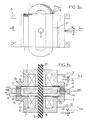
- Figure 3a there is shown a top view of the mechanical part of the linear servo motor.
- the motor comprises the carcass 1 or frame, formed in fact of the electromagnet and against the electromagnet as previously mentioned.
- the carcass 1 as well as the carcass 1 'of the electromagnet against can advantageously be formed by a magnetic circuit 9, 10, as well as shown in Figure 3b, which is a sectional view according to the plane of symmetry AA of FIG. 3a.
- Each magnetic circuit can advantageously be formed by a magnetic circuit made of ferromagnetic material laminated or sintered to limit losses magnetic.
- an electrical winding 11, respectively 12 is provided, to form the electromagnet, respectively against the electromagnet.
- Each winding is then powered by two power wires, F1, F2, respectively F3, F4.
- the electromagnet, respectively the counter electromagnet are kept at a fixed distance one of the other by mechanical connecting parts, noted 13, respectively 14, the part 15 as shown on FIGS. 3a and 3b used for fixing the carcass, for example.
- the mobile assembly is formed of a rod forming guide index 20 and made up of a plastic material, such as a plastic material of the type self-lubricating.
- Rod 20 is plugged into part 17 moving magnetic, itself formed by a plate in ferro-magnetic material sintered or laminated in order to limit the corresponding magnetic losses.
- the crew constituted by the rod 20 forming a guide index and by the moving magnetic part 17 is guided in translation by the guide index 20, which passes through the carcass 1, 1 'of the electromagnet, respectively of the electromagnet.
- the passages in the above-mentioned carcass are preferably adjusted so as to minimize friction between the rod itself 20, and the wall of the orifices allowing the passage thereof.
- Magnetic part 17 mobile is thus kept parallel to the electromagnet, respectively to the electromagnet, via above-mentioned adjusted passages, during its displacements during operation of the linear motor variable reluctance.
- the operating mode of the linear motor controlled by variable reluctance such as shown in Figure 2 and 3a, 3b is as follows.
- the symmetrical control circuit MCS advantageously comprises a circuit 30 detecting the differential displacement of the movable magnetic part 17, this detector circuit 30 delivering to the negative terminal of the subtractor 4 a signal sd representative of the differential displacement of the part magnetic mobile relative to the carcass 1, 1 ′, of the electromagnet and of the electromagnet against a position of origin of equilibrium.
- a current amplifier circuit supply, noted CAC, in symmetrical excitation, is supply, noted CAC, in symmetrical excitation, is planned, this circuit comprising, on the one hand, a module noted Symmetric control MOCS receiving error signal E delivered by the subtractor circuit 4, and delivering a first and second excitation control signal symmetrical, noted sa, sb.
- the current amplifier circuit symmetrical excitation supply, CAC comprises, on the other hand, two current amplifiers 7, 8 receiving the first respectively the second control signal of symmetrical excitation, and delivering to the winding the electromagnet 11, respectively of the electromagnet 12, an excitation supply current symmetrical corresponding.
- the principle of measuring the displacement of the mobile magnetic part 17 consists in measuring a quantity which varies with the air gaps 18 and 19 previously mentioned, and in particular the efa, efb, values of these, or better with their difference.
- the above measurement can be performed inductive or capacitive.
- the inductive method consists in measuring the inductance of the two windings 11 and 12, depending on the values corresponding air gap.
- the value of the aforementioned inductors can then be easily calculated by measuring, on the one hand, the voltage at terminals of each winding, and the derivative of the current supply of these, the value of the derivative of this current can be measured from a winding auxiliary of low known value, instantaneous voltage across this auxiliary winding representing the value of the winding supply current derivative considered.
- a measurement of the voltage U11, respectively U12, applied to the winding 11, respectively 12, of the electromagnet and of the electromagnet and the measurement of voltages across auxiliary windings 31 and 32, u11, u12, then allows to determine the corresponding values of L inductance of the electromagnet, respectively of against electromagnet, and ultimately, the values air gap efa, corresponding efb.
- the aforementioned voltage values can be measured by sampling, analog-to-digital conversion, the calculation can then be carried out from digitally for example.
- a more advantageous solution may consist in using an isolation transformer, supplied with the primary by the current I, which moreover makes it possible to adapt the level of the measured signal.
- the voltage u delivered by the secondary of the isolation transformer is thus proportional to dI / dt and to ef.
- CM Hall effect sensor is placed in the magnetic circuit of the transformer insulation, which delivers a proportional voltage U to I. This type of sensor is easy to implement.
- the sensor circuit 3 can advantageously be produced in the form of circuit 30 differential displacement detector, as shown in figures 2 and 4.
- the electromagnet and the counter-magnet, the mobile magnetic part 17, and the 2 air gaps 18 and 19 then constitute a double capacitor, which, as well as shown in Figure 4, is connected by connection wires F5, F6 and F7, to a measuring bridge comprising resistors equal 20 and 21.
- resistors can be made by precision resistors.
- the measuring bridge circuit advantageously comprises two first adjacent branches formed by the capacities of air gaps 18, 19 mentioned above, constituted by the carcass 1 of the electromagnet and the first side of part 17 moving magnetic opposite, respectively by the carcass 1 'of the electromagnet, and the second face of the movable magnetic part 17 opposite.
- the circuit bridge measurement includes two second branches adjacent formed by resistors, 20 and 21.
- a first diagonal of the circuit bridge measurement is formed by a generator 220 of signals periodicals whose fundamental frequency is very higher than the cut-off frequency of the linear motor enslaved.
- the fundamental frequency of the signal delivered by the generator 220 can be chosen equal to 50 kHz.
- the second diagonal of the measurement bridge delivers a differential measurement signal, denoted vm , between the movable magnetic part 17 and the common point of the two adjacent second branches formed by the standard resistors 20 and 21.
- a demodulator circuit 22 receives, on the one hand, the differential measurement signal, vm, and secondly, the periodic excitation signals, delivered by the generator 220, in order to ensure demodulation of the differential signal the demodulator circuit thus delivering classic way the signal amplitude signal envelope differential measurement vm. This signal is noted se on the figure 4.
- a filtering circuit 23 of the filter type low-pass is planned, this circuit receiving the envelope signal se, and delivering the signal sd representative of the displacement differential of the movable magnetic part 17.
- This filter removes demodulation products from high frequency.
- the detector device used as described in connection with FIGS. 3b and 4 is no longer a separate, expensive and bulky, which it is necessary to add.
- the insulating parts can also be in ceramic, which provides greater rigidity.
- the parts of the carcasses 1 and 1 'in opposite the first, respectively second side of the movable magnetic part 17 can advantageously be provided, as shown in Figure 3b, with a coating electrically conductive 110, 120.
- the coating electrically conductive can advantageously be formed by a metallized plastic film, the metallization of which is electrically connected or not to the potential of each carcass 1 or 1 'corresponding.
- Such a coating 110, 120 allows improve the assimilation of the characteristics of each capacitor formed by the air gaps efa, efb, to those of a flat capacitor, and therefore the accuracy of the measurement.
- the electrodes formed by the coating 110, 120 are disturbed by capacitive coupling to the coils 11 and 12, the potential of which is variable.
- the noise level of the sensor thus formed can be eliminated or strongly reduced by covering each coil with a shielding plate related to the reference potential.
- the armor plate, covering the coil, presents a cut so that this plate cannot constitute a turn surrounding completely an area subject to variable magnetic flux.
- Electrodes 110 or 120 can advantageously be configured according to a divided structure, in the absence of a loop, such as a comb structure.
- the shielding plate and the electrode can then be done using techniques flexible, double-sided printed circuits, the having the armor plate being applied to the corresponding coil.
- Demodulation performed by demodulator 22 provides a continuous output voltage thanks to the demodulation performed by signal frequency excitation delivered by generator 220, then at low-pass filtering by filter 23.
- the sd signal delivered at the output of the low-pass filter 23 and at the output of the detector circuit 3 or 30 is then proportional to the displacement d of the mobile magnetic part 17.
- the subtractor circuit 4 then performs the difference between the signal sd, representative of the displacement of the mobile magnetic part 17, and the signal control and movement, which of course represents the movement instruction for the crew constituted by the movable magnetic part 17 and by the index 20.
- the signal output ⁇ or error signal issued by subtractor 4 represents the error between the actual position and the position requested for the above-mentioned crew.
- the subtractor circuit 4 can advantageously be produced at by means of an operational amplifier mounted as an amplifier differential.
- the module MOCS of symmetrical linear control advantageously comprises a servo correction circuit 5, to ensure the stability of the servo in function of the mechanical impedance or load at which the motor, object of the present invention, is connected.
- This circuit receives the error signal ⁇ issued by the circuit subtractor 4 and delivers a corrected error signal ⁇ and.
- the circuit 5 servo corrector will not be described because It corresponds to a classic type circuit in the field servo motors, this type of circuit being intended before everything to improve the performance of the servo by response time and amortization terms.
- the linear symmetric control MOCS module further includes a linearizer circuit 6 allowing to control the windings 11, 12, the electromagnet, respectively of the electromagnet, in sanctuary of the current or the magnetic flux traversing these electromagnets, so as to make the displacement of the movable magnetic part 17 and of the index finger 2 linear along the direction of travel ⁇ with respect to to the input control signal e.
- circuit 6 linearizer A first embodiment of circuit 6 linearizer will be described in connection with Figure 5a.
- the circuit linearizer 6 advantageously comprises a circuit 24 rectifier-separator delivering from the error signal corrected ⁇ and, delivered by the servo correction circuit 5, positive and negative alternations, corrected by the corrected error signal ⁇ and.
- the circuit 24 actually delivers positive values, respectively negative, rectified, of the corrected error signal ⁇ and, this one being presumed to correspond to an input signal alternative e for which the error signal E and the signal corrected error ⁇ and are themselves formed by a signal to positive and negative alternation.
- circuit 24 separator rectifier may consist of two alternation alignment circuits of the conventional type, a first circuit to align the half-waves positive from the value 0, and a second circuit, similar to the first, allowing to align the alternations negative on the value 0.
- This type of classic circuit does not will not be described because perfectly known to the man of job.
- the linearizer circuit 6 can advantageously comprise a first, 25a, and a second, 25b, circuit for calculating the square root of the amplitude of the positive and negative alternations, rectified by the signal d 'error corrected ⁇ and.
- the aforementioned circuits 25a and 25b can be produced by analog circuits and deliver proportional signals, respectively to ⁇ at and ⁇ b .
- the linearizer circuit 6 comprises a first, 27a, and a second, 27b, correction multiplier circuit receiving the signals respectively. ⁇ at , respectively ⁇ b , delivered by the calculation circuits 25a, 25b.
- a subtractor circuit 26a and a summing circuit 26b receive, on the one hand, the differential detection signal sd, proportional to d, displacement of the movable magnetic part 17, and, on the other hand, a signal representative of the value eo of the air gaps when the movable magnetic part 17 is in the middle position and deliver signals representative of the values eo-d, eo + d to the first, 27a, respectively second, 27b, correction circuit.
- circuits 27a and 27b deliver a first, sa, respectively a second, sb, control signal symmetrical to the first, 7, respectively second, 8, current amplifier.
- the linearizer circuit 6, as shown in Figure 5a, ensures linearization of the non-linear characteristic of electromagnets, with regard to concerns the expression of strength that these produce according to the intensity traversing the corresponding windings.
- the aforementioned force therefore varies as the square of the current and as the inverse of the square of the value of the air gap.
- the control signal ⁇ and of the linearizer 6 represents the force setpoint. This is, first place, separated in its positive part and in its negative part by circuit 24 described previously due to the fact that an electromagnet can only produce forces attractive. According to the sign of the force to be produced, it is necessary to supply one or other of the windings of the electromagnet, respectively of the electromagnet.
- the circuit 25a or 25b allows to calculate the square root of the signal, and circuit 27a or 27b multiplies the result by a voltage representative of the instantaneous value of the air gap, that is to say proportional to e0 + d or to eO-d, depending on the value efa, efb of the air gap 18 or 19 considered.
- the enslavement can be made more efficient by the enslavement of the magnetic flux in the electromagnet and the electromagnet against the value of movement command setpoint signal e and no longer by controlling the current.
- the frame 1 of the electromagnet and the carcass 1 'of the electromagnet have advantageously at the air gap 18, 19 a probe Hall effect measurement 27.29, as shown for example in Figure 3b.
- the Hall effect measuring probe 27,29 delivers, via connection wires F8, F9, a signal representative of the magnetic flux generated in the air gap 18, 19 corresponding to the current amplifier 7, respectively 8, as shown in FIG. 2.
- the magnetic flux in the air gap is proportional to the entry of current amplifiers 7 and 8.
- the linearizer circuit is simplified and includes, a rectifier-separator circuit 24 delivering, from the corrected error signal ⁇ and delivered by the servo-correction circuit 5, the positive half-waves , respectively negative, rectified by the corrected error signal ⁇ and as described above in connection with FIG. 5a followed by a first, 25a, and a second, 25b, circuit for calculating the square root of the amplitude positive alternations, respectively negative, rectified by the corrected error signal ⁇ and.
- Each calculation circuit 25a, 25b delivers a proportional signal, respectively to ⁇ at , ⁇ b , respectively constituting the differential control signals, sa, sb.
- the linearizer 6 contains only the first two stages of the linearizer shown in Figure 5a.
- the correction of non-linearity due to the dependence of the force, exerted by the electromagnet respectively the electromagnet, because of the square of the current flowing through their coil the magnetic flux thus created is obtained by introduction into the feedback loop of the servo, that is to say at the level of the connection wires F8, F9, Hall effect probes to amplifiers 7, respectively 8, of a square function operating circuit, delivering to the winding 11, 12, of the electromagnet respectively of the counter electro magnet a signal proportional to the square of the magnetic flux generated in each corresponding air gap 18, 19 (the linearizer circuit 6 of FIG. 5b comprises then the only circuit 24 rectifier-separator described previously in connection with FIG. 5a).
- the linearizer circuit 6 of FIG. 5b comprises then the only circuit 24 rectifier-separator described previously in connection with FIG. 5a).
- circuit servo controller 5 and linearizer circuit 6 can be either analog or digital.
- these circuits can be advantageously carried out by means of a fast processor of signals such as the processor marketed under the reference TMS 320 C 25 by the company TEXAS INSTRUMENTS.
- the circuit servo corrector 5 is achieved by means operational amplifiers and the linearizer circuit 6 can be made from analog multipliers such as that the circuit marketed under the reference AD 534 by the ANALOG DEVICES company, these circuits allowing to realize square root and multiplication operations.
- the aforementioned Hall effect sensors can be placed either in the air gap, or, more advantageously, in the magnetic circuit or in a derivation of this last, so as to deliver a signal representative of the flow spawned in the air gap.
- a description of a variant of realization of the linearizer described previously in connection with Figures 2 and 5b will now be given in conjunction with FIG. 5c, in the context of a numerical control, in principle more precise than an analog control.
- the linearizer described previously in the description feeds only one coil 11 or 12 at a time. he is therefore likely to cause a distortion at the moment through the zero value of the applied force.
- the coils used have in principle a strong impedance to current transients, so that the current in the energized coil does not have the time to establish when the current in the coil switched to stop becomes zero. This results in a corresponding disturbance of the force produced.
- digital control allows to use linearization laws or processes much finer than just calculating the square root previously described.
- the linearization process can consist in supplying each coil 11, 12, with a current of the same intensity I o when the requested force is zero.
- the forces produced by each coil 11, 12, on the moving part 17 compensate each other.
- the linearizer 6 is controlled in differential mode, the current in one of the coils is increased to a value I o + i, that in the other coil is decreased to the symmetrical value I o -i.
- the current in the corresponding coil becomes zero and that in the other coil reaches then exceeds 2 I o , and can then be determined according to the law of the square root, since we return to the case previously described in the description where only one of the coils 11, 12 is supplied.
- the air gap compensations are carried out from the same way as described previously.
- circuits correctors 5, and linearizer 6, with where appropriate the air gap correction 60 can be achieved by a digital processor programmed to deliver the magnetic flux setpoints Fa and Fb such as represented in FIG. 5c, for a force setpoint F given following the processing of the correction module, in the differential or exclusive supply conditions for two respectively of a single coil 11, 12.
- FIGS. 6a and 6b An alternative embodiment of a linear motor will be described in connection with FIGS. 6a and 6b in the case where the part mobile magnetic 17 is likely to be subjected to displacement in rotation, around a center of rotation C.
- the same reference numbers denote the same elements as in the figures earlier.
- the winding 11 is placed around the displacement path linear ⁇ , which corresponds to a rotational movement on a circular arc with an opening angle ⁇ f.
- the movable magnetic part 17 is movable in rotation, in the direction of travel ⁇ , and guided mechanically so as to have only one degree of freedom per compared to the frame 1 of the electromagnet.
- the management of displacement ⁇ is then substantially tangent to that of lines of the magnetic field created by the electromagnet 11 in the air gap.
- the movable magnetic part 17 is subjected to a rotational displacement relative to a center of rotation C and is rotatably mounted relative to an axis of rotation 21 mechanically secured to the carcass 1 and orthogonal to the displacement path ⁇ .
- FIG. 6b a variant of embodiment similarly to Figure 2 a magnet 11 and a counter magnet 12.
- a deflection angle ⁇ f M or ⁇ a M , ⁇ b M , of the mobile magnetic part less than or equal to 10 degrees.
- variable reluctance linear motor object of the present invention as shown in FIGS. 6a or 6b, in its rotational displacement version can be used in all cases where we have to control precisely low amplitude oscillating rotational movements at high frequency, for example for active monitoring of pressure pulsations in the flows using a swinging butterfly mounted for rotation in a tube.
- the reluctance-controlled linear motor variable object of the present invention is, of a second part, particularly advantageous insofar as a linearity of movement of the moving equipment, dependent only performance of electronic components constitutive of the servo chain, can be obtained, the linearity defect of the whole system can then be made equal to a value of the order of 0.1%.
- the linearity characteristic of the response of the linear servo motor, object of this invention associated with the value of the bandwidth or the cutoff frequency of this allows to consider the corresponding reproductive applications sound
- the linear motor with variable reluctance object of the present invention then playing the role of a transducer comparable, and in any case superior, to the motor classical type electrodynamics, the relative stress to the mechanical impedance of the associated membrane in a such application to the mobile crew, and in particular to the guide index 20 of the linear motor to constitute for example a speaker, which can be made as low as possible, or in any case completely compensated by the circuit servo controller 5 and by the circuit linearizer to ensure faithful signal reproduction order and the translation of it in the form of corresponding sound vibrations.
Landscapes
- Engineering & Computer Science (AREA)
- Physics & Mathematics (AREA)
- General Engineering & Computer Science (AREA)
- Electromagnetism (AREA)
- Power Engineering (AREA)
- Mechanical Engineering (AREA)
- General Physics & Mathematics (AREA)
- Acoustics & Sound (AREA)
- Aviation & Aerospace Engineering (AREA)
- Control Of Linear Motors (AREA)
- Reciprocating, Oscillating Or Vibrating Motors (AREA)
- Electrostatic, Electromagnetic, Magneto- Strictive, And Variable-Resistance Transducers (AREA)
- Control Of Position Or Direction (AREA)
Claims (12)
- Linearservomotor mit veränderlicher Reluktanz, enthaltend einen Elektromagneten (1, 9, 11; 1, 1', 9, 10, 11, 12), der im Betrieb eine Zugkraft ausübt und einen Kern (1; 1, 1') enthält, der einen Magnetkreis (9; 9, 10) bildet, ferner eine Wicklung (11; 11, 12), die eine lineare Bewegungsbahn umschließt, weiterhin einen Magnetteil (17), der in einer Bewegungsrichtung beweglich ist und mechanisch derart geführt ist, daß er gegenüber dem Kern (1; 1, 1') des Elektromagneten einen einzigen Freiheitsgrad besitzt, wobei die Bewegungsrichtung im wesentlichen tangential zur Richtung der vom Elektromagneten erzeugten Kraftlinien des Magnetfeldes verläuft, ferner enthaltend eine Meßeinrichtung (3; 30), die ein Signal (sd) liefert, das repräsentativ für die Bewegung des beweglichen Magnetteiles (17) ist, wobei diese Meßeinrichtung mit einem Aufnehmer verbunden ist (F7), der mit induktiven oder kapazitiven Elementen versehen ist, die auf die Größe des zwischen dem Kern (1; 1, 1') und dem beweglichen Teil (17) bestehenden Spaltes (18) ansprechen, ferner enthaltend eine Subtraktionseinrichtung (4), die an einem ersten, positiven Eingang ein Signal (e) zur Steuerung der Bewegung des beweglichen Magnetteiles (17) erhält und an einem zweiten, negativen Eingang das Signal, das repräsentativ für die Bewegung ist, so daß diese Subtraktionseinrichtung (4) ein Fehlersignal (ε) entsprechend der Abweichung der Bewegung des beweglichen Teiles (17) vom Steuersignal dieser Bewegung liefert, weiterhin enthaltend einen Stromverstärkerkreis (CAC), der das Fehlersignal (ε) erhält und einen Speisestrom für die Wicklung (11; 11, 12) liefert, enthaltend schließlich eine Rückführeinrichtung (28; 12) für den beweglichen Magnetteil (17), der auf diesen Magnetteil eine Rückführkraft ausübt, die der vom Elektromagneten erzeugten Kraft entgegenwirkt, dadurch gekennzeichnet, daß die induktiven Elemente des Aufnehmers aus den Wicklungen (11; 11, 12) des Elektromagneten und die kapazitiven Elemente aus dem Kondensator bestehen, der vom Elektromagneten, dem Spalt (18) und dem beweglichen Magnetteil (17) gebildet wird.
- Linearmotor nach Anspruch 1, dadurch gekennzeichnet, daß er einen im wesentlichen symmetrischen Aufbau besitzt und daß die Rückführeinrichtung (12) gebildet wird durcheinen gleichartig wie der Elektromagnet ausgebildeten Gegenelektromagneten, wobei der Gegenelektromagnet und der Elektromagnet einander gegenüber angeordnet und Kerne (1', 1) auf beiden Seiten des beweglichen Magnetteiles (17) vorgesehen sind, einen zur Führung des beweglichen Magnetteiles dienender Finger (20) symmetrisch gegenüber dem beweglichen Magnetteil (17) angeordnet ist und die Führung dieses Fingers gleichzeitig durch den Kern (1) des Elektromagneten und den Kern (1') des Gegenelektromagneten bewirkt wird;sowie Steuerelemente (MCS) zur symmetrischen Steuerung des Elektromagneten bzw. des Gegenelektromagneten, wobei diese Steuerelemente einen Speisestrom zur symmetrischen Erregung an die jeweilige Spule (11, 12) von Elektromagnet bzw. Gegenelektromagnet liefern.
- Linearmotor nach Anspruch 2, dadurch gekennzeichnet, daß die Steuerelemente zur symmetrischen Steuerung wenigstens eine Detektoreinrichtung (30) zur Feststellung einer Differential-Bewegung des beweglichen Magnetteiles (17) enthalten, wobei diese Detektoreinrichtung (30) an den negativen Anschluß der Subtraktionseinrichtung (4) ein Signal (sd) liefert, das repräsentativ ist für die differentielle Bewegung des beweglichen Magnetteiles (17) gegenüber dem Kern (1, 1') des Elektromagneten und des Gegenelektromagneten bezogen auf eine ursprüngliche Gleichgewichtsstellung.
- Linearmotor nach Anspruch 2 oder 3, dadurch gekennzeichnet, daß die Steuerelemente (MCS) zur symmetrischen Steuerung außerdem eine Stromverstärkerschaltung (CAC) für symmetrische Erregung enthalten, die einerseits ein Modul (MOCS) für symmetrische Steuerung aufweist, das das von der Subtraktionseinrichtung (4) gelieferte Fehlersignal aufnimmt und ein erstes sowie zweites Steuersignal symmetrischer Erregung (sa, sb) liefert, und die andererseits zwei Stromverstärker (7, 8) enthält, die das erste bzw. zweite Steuersignal symmetrischer Erregung erhalten und die an die Wicklung des Elektromagneten (11) bzw. des Gegenelektromagneten (12) einen Speisestrom zur symmetrischen Erregung liefern.
- Linearmotor nach Anspruch 3, dadurch gekennzeichnet, daß die Detektoreinrichtung (30) zur Feststellung einer differentiellen Bewegung eine induktive Bauweise aufweist und eine Messung der Induktivität der beiden Wicklungen (11, 12) des Elektromagneten und des Gegenelektromagneten ermöglicht, wobei diese Detektoreinrichtung folgende Elemente enthältElemente zur Messung der Spannung (U11 bzw. U12) an der Wicklung (11 bzw. 12) des Elektromagneten bzw. des Gegenelektromagneten,Elemente zur Messung der Ableitung (u11, u12) des Speisestromes der Wicklung (11 bzw. 12) des Elektromagneten bzw. des Gegenelektromagneten,Rechenelemente zur Bestimmung der Induktivität L des Elektromagneten (11) bzw. des Gegenelektromagneten (12) und der entsprechenden Spaltwerte (efa, efb), wobei die Induktivität L durch die Beziehung gegeben ist:
- Linearmotor nach Anspruch 3, dadurch gekennzeichnet, daß die Detektoreinrichtung (30) zur Bestimmung der differentiellen Bewegung eine kapazitive Bauweise aufweist und durch folgende Elemente gebildet wird:eine Brückenschaltung, enthaltendzwei aneinanderstoßende erste Zweige, die von den Kapazitäten der Spalte (18, 19) gebildet werden, die zwischen dem Kern (1) des Elektromagneten und der gegenüberliegenden ersten Seite des beweglichen Magnetteiles (17) bzw. zwischen dem Kern (1') des Gegenelektromagneten und der gegenüberliegenden zweiten Seite des beweglichen Magnetteiles (17) vorhanden sind,zwei benachbarte zweite Zweige, die von gleichen Widerständen (20, 21) gebildet werden,eine erste Diagonale, die von einem Generator (220) zur Erzeugung periodischer Signale gebildet wird, deren Grundfrequenz wesentlich höher als die Abschaltfrequenz des Linearservomotors ist,eine zweite Diagonale, die ein differentielles Meßsignal (vm) liefert und zwischen dem beweglichen Magnetteil (17) und dem gemeinsamen Punkt der beiden zweiten benachbarten Brückenzweige angeordnet ist,eine Demodulatorschaltung (22) für die Frequenz der periodischen Signale, wobei diese Demodulatorschaltung das differentielle Meßsignal erhält und ein Signal liefert, das der Umhüllenden der Amplitude des differentiellen Signales entspricht,einen als Tiefpaß ausgebildeten Filterkreis (23), der das genannte Signal der Umhüllenden erhält und ein Signal (sd) liefert, das repräsentativ für die differentielle Bewegung des beweglichen Magnetteiles ist.
- Linearmotor nach Anspruch 4, dadurch gekennzeichnet, daß das Modul (MOCS) zur symmetrischen Linearsteuerung folgende Schaltungen enthälteine Servokorrekturschaltung (5), die die Stabilität der Servosteuerung in Abhängigkeit von der mechanischen Impedanz bzw. Belastung gewährleistet, mit der der Motor verbunden ist, wobei diese Schaltung das Fehlersignal (ε) erhält und ein korrigiertes Fehlersignal (ε and) liefert,eine Linearisierungsschaltung (6), die eine Steuerung der Wicklungen (11, 12) des Elektromagneten bzw. des Gegenelektromagneten in Servoabhängigkeit vom Strom oder vom Magnetfluß bewirkt, so daß die Bewegung des beweglichen Magnetteiles (17) linear in Bewegungsrichtung (Δ) bezogen auf das Eingangssteuersignal (e) gemacht wird.
- Linearmotor nach Anspruch 7, dadurch gekennzeichnet, daß für den Fall einer Strom-Servosteuerung die Gleichrichtungs-Linearisierungsschaltung (6) folgende Teile enthält:eine Gleichrichter-Trennschaltung (24), die ausgehend von dem korrigierten Fehlersignal (ε and), das von der Servokorrekturschaltung (5) geliefert wird, gleichgerichtete positive bzw. negative Halbwellen des korrigierten Fehlersignales (ε and) liefert,eine erste und eine zweite Rechenschaltung (25a, 25b) zur Bestimmung der Quadratwurzel der Amplitude der gleichgerichteten positiven bzw. negativen Halbwellen des korrigierten Fehlersignales (ε and) und zur Lieferung von zwei Signalen proportionaleine erste und eine zweite Korrektur-Multiplizierschaltung (27a, 27b), die die Signale (
- Linearmotor nach Anspruch 7, dadurch gekennzeichnet, daß im Falle einer Servosteuerung entsprechend dem Magnetfluß des Elektromagneten und des Gegenelektromagneten der Kern (1) des Elektromagneten auf dem Niveau des Spaltes (18, 19) eine zur Messung des Hall-Effektes dienende Sonde (27) aufweist, die an den Stromverstärker (7 bzw. 8) ein Signal liefert, das repräsentativ für den in diesem Spalt erzeugten Magnetfluß ist.
- Linearmotor nach Anspruch 9, dadurch gekennzeichnet, daß die Linearisierungsschaltung (6) folgende Teile enthält:eine Gleichrichter-Trennschaltung (24), die ausgehend von dem korrigierten Fehlersignal (ε and), das von der Servokorrekturschaltung (5) geliefert wird, die gleichgerichteten positiven bzw. negativen Halbwellen des korrigierten Fehlersignales (ε and) liefert,eine erste und eine zweite Rechenschaltung (25a, 25b) zur Bestimmung der Quadratwurzel der Amplitude der gleichgerichteten positiven bzw. negativen Halbwellen des korrigierten Fehlersignales (ε and), wobei diese Rechenschaltungen zwei Signale proportional (
- Linearmotor nach Anspruch 7 oder 9, dadurch gekennzeichnet, daß die Servokorrekturschaltung (5) und die Linearisierungsschaltung (6) durch einen programmierten numerischen Prozessor gebildet werden, der ausgehend von magnetischen Flußsignalen (Fa, Fb) Stromsignale erzeugt, wobei die Linearisierungsschaltung in jeder Wicklung (11, 12) einen Strom vorgegebener gleicher Größe erzeugt, wenn die gewünschte Kraft gleich null ist, dagegen einen Strom, der um einen differentiellen Wert in der einen bzw. anderen Wicklung gegenüber dem Strom vorgegebener Stärke vergrößert oder verkleinert ist, solange die gewünschte Kraft einen vorbestimmten Wert nicht übersteigt, und die dann, wenn die gewünschte Kraft hohe Werte erreicht, die über dem vorbestimmten Wert der gewünschten Kraft liegen, einen Strom null bzw. einen Strom, der mehr als zweimal so groß wie der Strom vorgegebener Stärke ist, erzeugt.
- Linearmotor nach einem der Ansprüche 1 bis 11, dadurch gekennzeichnet, daß zur Erzeugung eines Motors, dessen beweglicher Teil (17) eine Drehbewegung gegenüber einem Rotationszentrum (C) ausführt, der bewegliche Magnetteil (17) eine Rotationsachse (21) aufweist, die mechanisch fest mit dem Kern (1) verbunden ist und senkrecht zur Bewegungsbahn verläuft, wobei der bewegliche Magnetteil drehbeweglich um diese Drehachse (21) angeordnet ist.
Applications Claiming Priority (2)
| Application Number | Priority Date | Filing Date | Title |
|---|---|---|---|
| FR9114576 | 1991-11-26 | ||
| FR9114576A FR2684251B1 (fr) | 1991-11-26 | 1991-11-26 | Moteur lineaire asservi a reluctance variable. |
Publications (2)
| Publication Number | Publication Date |
|---|---|
| EP0544576A1 EP0544576A1 (de) | 1993-06-02 |
| EP0544576B1 true EP0544576B1 (de) | 1998-10-28 |
Family
ID=9419337
Family Applications (1)
| Application Number | Title | Priority Date | Filing Date |
|---|---|---|---|
| EP92403147A Expired - Lifetime EP0544576B1 (de) | 1991-11-26 | 1992-11-23 | Linear Servomotor mit veränderlicher Reluktanz |
Country Status (6)
| Country | Link |
|---|---|
| US (1) | US5621293A (de) |
| EP (1) | EP0544576B1 (de) |
| JP (1) | JP2749748B2 (de) |
| DE (1) | DE69227435T2 (de) |
| ES (1) | ES2122988T3 (de) |
| FR (1) | FR2684251B1 (de) |
Families Citing this family (32)
| Publication number | Priority date | Publication date | Assignee | Title |
|---|---|---|---|---|
| FR2705395B1 (fr) * | 1993-05-13 | 1995-07-28 | Hutchinson | Double vitrage antivibratoire. |
| FR2711408B1 (fr) * | 1993-10-19 | 1995-12-22 | Hutchinson | Perfectionnements aux dispositifs antivibratoires hydrauliques. |
| DE4447537B4 (de) * | 1994-02-28 | 2006-04-20 | Temic Automotive Electric Motors Gmbh | Verfahren und System zur aktiven Schwingungsdämpfung |
| DE4406481C3 (de) * | 1994-02-28 | 2002-04-25 | Isad Electronic Sys Gmbh & Co | Anlasser für Antriebsaggregate, insbesondere Verbrennungsmotoren |
| US5754017A (en) * | 1995-12-26 | 1998-05-19 | Asmo Co., Ltd. | Power window with detecting function of sticking of foreign matter |
| FR2753873B1 (fr) * | 1996-09-24 | 2003-06-20 | Thomson Marconi Sonar Sas | Procede d'asservissement d'un transducteur a reluctance variable, et moteur lineaire pour la mise en oeuvre d'un tel procede |
| DE19716540A1 (de) * | 1997-04-19 | 1998-10-22 | Bosch Gmbh Robert | Elektromagnet zur Betätigung des Stellglieds eines Ventils |
| FR2765647B1 (fr) * | 1997-07-07 | 2002-01-11 | Jacques Clausin | Reducteur de vibrations monoaxe accorde a bande large et de grande legerete |
| FR2766607B1 (fr) * | 1997-07-23 | 1999-10-01 | Hutchinson | Actionneur electromagnetique, et support antivibratoire hydraulique comportant un tel actionneur |
| WO1999021198A1 (fr) * | 1997-10-17 | 1999-04-29 | Jacques Clausin | Dispositif de commande proportionnelle de force delivree par un electro-aimant independante des variations des tensions d'alimentation et des entrefers |
| FR2775538B1 (fr) * | 1998-03-02 | 2000-04-28 | Valeo Systemes De Fermetures | Actionneur electro-mecanique auto-asservi en position et vehicule automobile equipe de cet actionneur |
| FR2793941B1 (fr) | 1999-05-17 | 2001-08-03 | Hutchinson | Actionneur electromagnetique |
| GB2354054B (en) * | 1999-09-03 | 2001-08-08 | Avon Vibration Man Syst Ltd | Controlling vibrations |
| JP2001221653A (ja) | 1999-12-01 | 2001-08-17 | Honda Motor Co Ltd | 変位検出装置 |
| US6388417B1 (en) | 1999-12-06 | 2002-05-14 | Macrosonix Corporation | High stability dynamic force motor |
| EP1428236A4 (de) * | 2001-06-21 | 2009-08-26 | Honeywell Int Inc | Solenoid-betätigungsglied mit positionsunabhängiger kraft |
| US6701876B2 (en) * | 2001-09-27 | 2004-03-09 | Visteon Global Technologies, Inc. | Electromechanical engine valve actuator system with reduced armature impact |
| US6895809B2 (en) * | 2002-12-31 | 2005-05-24 | Spx Corporation | Method and apparatus for testing a motor |
| US7501834B2 (en) * | 2005-06-21 | 2009-03-10 | Custom Sensors & Technologies, Inc. | Voice coil actuator with embedded capacitive sensor for motion, position and/or acceleration detection |
| US7345372B2 (en) * | 2006-03-08 | 2008-03-18 | Perpetuum Ltd. | Electromechanical generator for, and method of, converting mechanical vibrational energy into electrical energy |
| WO2007134287A1 (en) * | 2006-05-12 | 2007-11-22 | Parker-Hannifin Corporation | Displacement measurement device |
| CN100593767C (zh) * | 2006-06-30 | 2010-03-10 | 深圳市大族激光科技股份有限公司 | 电容传感器的控制方法 |
| KR101013588B1 (ko) | 2008-10-14 | 2011-02-14 | 한국철도기술연구원 | 선형동기전동기의 위치검출장치 |
| CN101850523B (zh) * | 2010-03-18 | 2011-12-07 | 沈阳工业大学 | 数控机床直线同步电动机磁悬浮进给平台 |
| DE102010061955B4 (de) * | 2010-11-25 | 2014-03-13 | Rolls-Royce Deutschland Ltd & Co Kg | Induktiver Sensor |
| AT513617B1 (de) * | 2012-12-21 | 2014-06-15 | Seh Ltd | Magnetvorrichtung umfassend eine auf den Translator wirkende Beschleunigungseinheit |
| WO2015030709A1 (en) * | 2013-08-26 | 2015-03-05 | Halliburton Energy Services, Inc. | Variable reluctance transducers |
| KR20170060114A (ko) | 2014-09-24 | 2017-05-31 | 택션 테크놀로지 인코포레이티드 | 오디오-주파수 진동들에 대해 댐핑된 전자기적으로 작동된 평면형 모션을 생성하기 위한 시스템들 및 방법들 |
| US10573139B2 (en) | 2015-09-16 | 2020-02-25 | Taction Technology, Inc. | Tactile transducer with digital signal processing for improved fidelity |
| CN108111088B (zh) * | 2017-12-23 | 2020-08-18 | 西安交通大学 | 一种考虑气隙波动的永磁同步直线电机推力精确预测方法 |
| FR3118257A1 (fr) * | 2020-12-18 | 2022-06-24 | Sagemcom Broadband Sas | Procédé et dispositif de transmission de signaux optiques à puissance moyenne adaptée à la température et au vieillissement, programme informatique et support de programme correspondants. |
| CN117938018B (zh) * | 2024-03-20 | 2024-07-12 | 深圳大学 | 一种调姿平台的电机姿态控制方法、装置及设备 |
Family Cites Families (27)
| Publication number | Priority date | Publication date | Assignee | Title |
|---|---|---|---|---|
| US4041529A (en) * | 1976-04-12 | 1977-08-09 | The Raymond Lee Organization, Inc. | Airplane route viewing system |
| JPS5355597A (en) * | 1976-10-28 | 1978-05-20 | Inoue Japax Res Inc | Device for horizontally moving working table or spindle |
| JPS54149030A (en) * | 1978-05-15 | 1979-11-21 | Babcock Hitachi Kk | Two-layer type low-pollution combustion device |
| LU80496A1 (fr) * | 1978-11-09 | 1980-06-05 | Cockerill | Procede et diopositif pour le depot electrolytique en continu et a haute densite de courant d'un metal de recouvrement sur une tole |
| US4331263A (en) * | 1979-11-30 | 1982-05-25 | Christopher Scientific Co., Inc. | Control unit for use in a vibratory feeder system |
| US4352048A (en) * | 1980-02-19 | 1982-09-28 | Ontrax Corporation | Electromagnetic actuator apparatus |
| US4431985A (en) * | 1981-03-02 | 1984-02-14 | Honeywell Inc. | Stepper motor system for digitally measuring input quantities |
| US4370604A (en) * | 1981-06-25 | 1983-01-25 | Honeywell Inc. | Solenoid actuated servo system |
| JPS59132765A (ja) * | 1983-01-20 | 1984-07-30 | Nippon Telegr & Teleph Corp <Ntt> | 傾斜駆動制御装置 |
| JPS608540A (ja) * | 1983-06-27 | 1985-01-17 | Nissan Motor Co Ltd | 防振装置 |
| JPS6187151A (ja) * | 1984-09-11 | 1986-05-02 | Toray Ind Inc | 画像形成膜の製造方法 |
| IE55855B1 (en) * | 1984-10-19 | 1991-01-30 | Kollmorgen Ireland Ltd | Position and speed sensors |
| US4616153A (en) * | 1984-12-10 | 1986-10-07 | Lee Robert E | Closed-loop linear position servomotor |
| JPS61214011A (ja) * | 1985-03-20 | 1986-09-22 | Res Dev Corp Of Japan | 可動鉄片型電磁石アクチユエ−タ |
| JPH0619668B2 (ja) * | 1985-03-22 | 1994-03-16 | 新技術事業団 | 可動鉄心型電磁石アクチユエ−タ |
| DE3515350A1 (de) * | 1985-04-27 | 1987-01-22 | Messerschmitt Boelkow Blohm | Magnetregler fuer langstator-magnetschwebefahrzeuge |
| SU1280318A1 (ru) * | 1985-06-05 | 1986-12-30 | Специальное Конструкторско-Технологическое Бюро С Опытным Производством Минского Радиотехнического Института | Оптико-электронное устройство дл измерени линейных перемещений |
| JPS62123578A (ja) * | 1985-11-22 | 1987-06-04 | Toshiba Corp | 郵便番号自動読取区分装置 |
| DE3628535A1 (de) * | 1986-08-22 | 1988-03-03 | Vdo Schindling | Anordnung zur betaetigung eines stellgliedes |
| JPS63136113A (ja) * | 1986-11-26 | 1988-06-08 | Koyo Seiko Co Ltd | 磁気浮上スライド装置 |
| US4717865A (en) * | 1987-05-29 | 1988-01-05 | Westinghouse Electric Corp. | Transportation apparatus |
| GB8814777D0 (en) * | 1988-06-22 | 1988-07-27 | Renishaw Plc | Controlled linear motor |
| US4914726A (en) * | 1989-01-17 | 1990-04-03 | Tektronix, Inc. | Mass velocity controller |
| JPH07108101B2 (ja) * | 1989-02-28 | 1995-11-15 | オ−クマ株式会社 | リニアアクチュエータ駆動制御装置 |
| DE3918753C1 (de) * | 1989-06-08 | 1990-07-12 | Fa. Carl Freudenberg, 6940 Weinheim, De | |
| FR2666858B2 (fr) * | 1990-01-30 | 1992-12-31 | Hutchinson | Perfectionnements aux dispositifs antivibratoires hydrauliques. |
| US5257681A (en) * | 1992-09-28 | 1993-11-02 | Trw Inc. | Apparatus for damping movement |
-
1991
- 1991-11-26 FR FR9114576A patent/FR2684251B1/fr not_active Expired - Fee Related
-
1992
- 1992-11-23 EP EP92403147A patent/EP0544576B1/de not_active Expired - Lifetime
- 1992-11-23 DE DE69227435T patent/DE69227435T2/de not_active Expired - Fee Related
- 1992-11-23 ES ES92403147T patent/ES2122988T3/es not_active Expired - Lifetime
- 1992-11-25 US US07/981,484 patent/US5621293A/en not_active Expired - Fee Related
- 1992-11-26 JP JP4317495A patent/JP2749748B2/ja not_active Expired - Lifetime
Also Published As
| Publication number | Publication date |
|---|---|
| ES2122988T3 (es) | 1999-01-01 |
| JP2749748B2 (ja) | 1998-05-13 |
| DE69227435T2 (de) | 1999-04-22 |
| FR2684251A1 (fr) | 1993-05-28 |
| JPH05300718A (ja) | 1993-11-12 |
| US5621293A (en) | 1997-04-15 |
| EP0544576A1 (de) | 1993-06-02 |
| FR2684251B1 (fr) | 1995-07-28 |
| DE69227435D1 (de) | 1998-12-03 |
Similar Documents
| Publication | Publication Date | Title |
|---|---|---|
| EP0544576B1 (de) | Linear Servomotor mit veränderlicher Reluktanz | |
| EP1584899B1 (de) | Positionssensor eines Ventilschalters an einem Verbrennungsmotor | |
| EP0749538B1 (de) | Aktives magnetlager mit positions-selbsterfassung | |
| EP0320341B1 (de) | Strommessgerät mit magnetischer Kopplung | |
| EP1012609A1 (de) | Gerät mit bandpass grosser bandbreite zum messen electrischer stromstärke ineinem leiter | |
| EP0665416A1 (de) | Magnetischer Lagesensor mit Hallsonde | |
| EP2288871B1 (de) | Trägheitsdrehungssensor mit driftkompensation | |
| EP0077739A1 (de) | Gerät zur Messung einer durch einen Ionenstrahl erzeugten Ionenströmung | |
| FR2519137A1 (fr) | Detecteur de position a deux axes pour dispositif a suspension magnetique | |
| FR3033647A1 (fr) | Capteur de courant pour mesurer un courant alternatif | |
| FR2640373A1 (fr) | Chaines de mesure dimensionnelle capacitive a sortie lineaire | |
| CH407345A (fr) | Appareil pour vérifier les caractéristiques ou la position d'un faisceau de particules chargées | |
| EP0780587A1 (de) | Magnetlager mit Stellgliedern und wechselständigen Messwertgebern | |
| EP0002417B1 (de) | Lageregelungsystem für ein bewegliches Organ in Abhängigkeit von digitalen Steuersignalen und digital-analoge Interfaceschaltung für ein solches System | |
| EP2511665B1 (de) | Vorrichtung zur axialen Positionserfassung einer Drehwelle, und Verwendung in einer Turbomolekularpumpe | |
| WO2008047001A2 (fr) | Dispositif inductif de mesure de la position d'une cible, et procede mis en oeuvre par ce dispositif | |
| EP0069073A1 (de) | Kraftmesseinrichtung | |
| WO2022090499A1 (fr) | Dispositif de détection du couplage capacitif entre un objet et une surface de détection | |
| EP1166295B1 (de) | Verfahren zur positionsbestimmung eines beweglichen elements in mindestens einem hauptluftspalt eines elektromagnetischen aktuators | |
| WO1980001951A1 (fr) | Capteur differentiel lineaire a courants de foucault servant a mesurer les petits deplacements d'une piece metallique | |
| FR2867819A1 (fr) | Palier magnetique actif a auto-detection de position | |
| FR2688586A1 (fr) | Capteur de position et application a la mesure de l'angle du papillon d'un carburateur. | |
| EP0692921B1 (de) | Schallaufnahmevorrichtung durch Elektretmikrofon | |
| CH578959A5 (de) | ||
| FR2628842A1 (fr) | Capteur inertiel composite du type mecanique |
Legal Events
| Date | Code | Title | Description |
|---|---|---|---|
| PUAI | Public reference made under article 153(3) epc to a published international application that has entered the european phase |
Free format text: ORIGINAL CODE: 0009012 |
|
| AK | Designated contracting states |
Kind code of ref document: A1 Designated state(s): BE DE ES FR GB IT LU NL SE |
|
| 17P | Request for examination filed |
Effective date: 19930413 |
|
| 17Q | First examination report despatched |
Effective date: 19950208 |
|
| APAB | Appeal dossier modified |
Free format text: ORIGINAL CODE: EPIDOS NOAPE |
|
| APAA | Appeal reference recorded |
Free format text: ORIGINAL CODE: EPIDOS REFN |
|
| APCB | Communication from the board of appeal sent |
Free format text: ORIGINAL CODE: EPIDOS OBAPE |
|
| APCB | Communication from the board of appeal sent |
Free format text: ORIGINAL CODE: EPIDOS OBAPE |
|
| APAB | Appeal dossier modified |
Free format text: ORIGINAL CODE: EPIDOS NOAPE |
|
| GRAG | Despatch of communication of intention to grant |
Free format text: ORIGINAL CODE: EPIDOS AGRA |
|
| GRAG | Despatch of communication of intention to grant |
Free format text: ORIGINAL CODE: EPIDOS AGRA |
|
| GRAH | Despatch of communication of intention to grant a patent |
Free format text: ORIGINAL CODE: EPIDOS IGRA |
|
| GRAH | Despatch of communication of intention to grant a patent |
Free format text: ORIGINAL CODE: EPIDOS IGRA |
|
| GRAA | (expected) grant |
Free format text: ORIGINAL CODE: 0009210 |
|
| AK | Designated contracting states |
Kind code of ref document: B1 Designated state(s): BE DE ES FR GB IT LU NL SE |
|
| PG25 | Lapsed in a contracting state [announced via postgrant information from national office to epo] |
Ref country code: LU Free format text: LAPSE BECAUSE OF NON-PAYMENT OF DUE FEES Effective date: 19981123 |
|
| REF | Corresponds to: |
Ref document number: 69227435 Country of ref document: DE Date of ref document: 19981203 |
|
| GBT | Gb: translation of ep patent filed (gb section 77(6)(a)/1977) |
Effective date: 19981127 |
|
| REG | Reference to a national code |
Ref country code: ES Ref legal event code: FG2A Ref document number: 2122988 Country of ref document: ES Kind code of ref document: T3 |
|
| PLBE | No opposition filed within time limit |
Free format text: ORIGINAL CODE: 0009261 |
|
| STAA | Information on the status of an ep patent application or granted ep patent |
Free format text: STATUS: NO OPPOSITION FILED WITHIN TIME LIMIT |
|
| 26N | No opposition filed | ||
| PGFP | Annual fee paid to national office [announced via postgrant information from national office to epo] |
Ref country code: NL Payment date: 20011016 Year of fee payment: 10 |
|
| PGFP | Annual fee paid to national office [announced via postgrant information from national office to epo] |
Ref country code: SE Payment date: 20011018 Year of fee payment: 10 |
|
| PGFP | Annual fee paid to national office [announced via postgrant information from national office to epo] |
Ref country code: ES Payment date: 20011112 Year of fee payment: 10 |
|
| PGFP | Annual fee paid to national office [announced via postgrant information from national office to epo] |
Ref country code: DE Payment date: 20011115 Year of fee payment: 10 |
|
| PGFP | Annual fee paid to national office [announced via postgrant information from national office to epo] |
Ref country code: GB Payment date: 20011116 Year of fee payment: 10 |
|
| PGFP | Annual fee paid to national office [announced via postgrant information from national office to epo] |
Ref country code: FR Payment date: 20011121 Year of fee payment: 10 |
|
| PGFP | Annual fee paid to national office [announced via postgrant information from national office to epo] |
Ref country code: BE Payment date: 20011129 Year of fee payment: 10 |
|
| REG | Reference to a national code |
Ref country code: GB Ref legal event code: IF02 |
|
| PG25 | Lapsed in a contracting state [announced via postgrant information from national office to epo] |
Ref country code: GB Free format text: LAPSE BECAUSE OF NON-PAYMENT OF DUE FEES Effective date: 20021123 |
|
| PG25 | Lapsed in a contracting state [announced via postgrant information from national office to epo] |
Ref country code: SE Free format text: LAPSE BECAUSE OF NON-PAYMENT OF DUE FEES Effective date: 20021124 Ref country code: ES Free format text: LAPSE BECAUSE OF NON-PAYMENT OF DUE FEES Effective date: 20021124 |
|
| PG25 | Lapsed in a contracting state [announced via postgrant information from national office to epo] |
Ref country code: BE Free format text: LAPSE BECAUSE OF NON-PAYMENT OF DUE FEES Effective date: 20021130 |
|
| BERE | Be: lapsed |
Owner name: *HUTCHINSON Effective date: 20021130 |
|
| PG25 | Lapsed in a contracting state [announced via postgrant information from national office to epo] |
Ref country code: NL Free format text: LAPSE BECAUSE OF NON-PAYMENT OF DUE FEES Effective date: 20030601 |
|
| PG25 | Lapsed in a contracting state [announced via postgrant information from national office to epo] |
Ref country code: DE Free format text: LAPSE BECAUSE OF NON-PAYMENT OF DUE FEES Effective date: 20030603 |
|
| EUG | Se: european patent has lapsed | ||
| GBPC | Gb: european patent ceased through non-payment of renewal fee | ||
| PG25 | Lapsed in a contracting state [announced via postgrant information from national office to epo] |
Ref country code: FR Free format text: LAPSE BECAUSE OF NON-PAYMENT OF DUE FEES Effective date: 20030731 |
|
| NLV4 | Nl: lapsed or anulled due to non-payment of the annual fee |
Effective date: 20030601 |
|
| REG | Reference to a national code |
Ref country code: FR Ref legal event code: ST |
|
| REG | Reference to a national code |
Ref country code: ES Ref legal event code: FD2A Effective date: 20031213 |
|
| APAH | Appeal reference modified |
Free format text: ORIGINAL CODE: EPIDOSCREFNO |
|
| PG25 | Lapsed in a contracting state [announced via postgrant information from national office to epo] |
Ref country code: IT Free format text: LAPSE BECAUSE OF NON-PAYMENT OF DUE FEES;WARNING: LAPSES OF ITALIAN PATENTS WITH EFFECTIVE DATE BEFORE 2007 MAY HAVE OCCURRED AT ANY TIME BEFORE 2007. THE CORRECT EFFECTIVE DATE MAY BE DIFFERENT FROM THE ONE RECORDED. Effective date: 20051123 |