EP0543520A1 - Sicherheitsgurt-Aufroller mit Klypengeräusch-Beseitigungsvorrichtung - Google Patents
Sicherheitsgurt-Aufroller mit Klypengeräusch-Beseitigungsvorrichtung Download PDFInfo
- Publication number
- EP0543520A1 EP0543520A1 EP92310002A EP92310002A EP0543520A1 EP 0543520 A1 EP0543520 A1 EP 0543520A1 EP 92310002 A EP92310002 A EP 92310002A EP 92310002 A EP92310002 A EP 92310002A EP 0543520 A1 EP0543520 A1 EP 0543520A1
- Authority
- EP
- European Patent Office
- Prior art keywords
- reel
- locking pawl
- belt
- retractor
- seat belt
- Prior art date
- Legal status (The legal status is an assumption and is not a legal conclusion. Google has not performed a legal analysis and makes no representation as to the accuracy of the status listed.)
- Granted
Links
Images

Classifications
-
- B—PERFORMING OPERATIONS; TRANSPORTING
- B60—VEHICLES IN GENERAL
- B60R—VEHICLES, VEHICLE FITTINGS, OR VEHICLE PARTS, NOT OTHERWISE PROVIDED FOR
- B60R22/00—Safety belts or body harnesses in vehicles
- B60R22/30—Coupling devices other than buckles, including length-adjusting fittings or anti-slip devices
-
- B—PERFORMING OPERATIONS; TRANSPORTING
- B60—VEHICLES IN GENERAL
- B60R—VEHICLES, VEHICLE FITTINGS, OR VEHICLE PARTS, NOT OTHERWISE PROVIDED FOR
- B60R22/00—Safety belts or body harnesses in vehicles
- B60R22/34—Belt retractors, e.g. reels
- B60R22/36—Belt retractors, e.g. reels self-locking in an emergency
- B60R22/41—Belt retractors, e.g. reels self-locking in an emergency with additional means for preventing locking during unwinding under predetermined conditions
-
- B—PERFORMING OPERATIONS; TRANSPORTING
- B60—VEHICLES IN GENERAL
- B60R—VEHICLES, VEHICLE FITTINGS, OR VEHICLE PARTS, NOT OTHERWISE PROVIDED FOR
- B60R22/00—Safety belts or body harnesses in vehicles
- B60R22/34—Belt retractors, e.g. reels
- B60R22/36—Belt retractors, e.g. reels self-locking in an emergency
- B60R22/40—Belt retractors, e.g. reels self-locking in an emergency responsive only to vehicle movement
Definitions
- This invention relates to belt retractors for vehicles and in particular to a rattle suppressor for quieting the rattle occasioned by free movement of the frame-mounted ratchet pawl common to many such devices.
- a ratchet wheel is formed on the seat belt retractor reel and is engageable during periods of rapid acceleration or deceleration of the vehicle by a pawl which prevents further withdrawal of the seat belt from the retractor housing.
- the pawl is typically biased by gravity into a non-engaging position with respect to the ratchet wheel.
- the freely movable pawl when not engaged with the seat belt by the urging of the inertial device which responds to vehicle acceleration and deceleration to actuate the pawl, is responsive to vibration of the vehicle, and, unless muffled or suppressed, can produce a rattling noise which may be disturbing to the driver and passengers, particularly to those who are unable to identify the rattle.
- the rattle is usually the result of metal-to-metal hitting of the pawl against the ratchet teeth on the ratchet wheels. It is accordingly the object of this invention to provide a rattle suppressing improvement for seat belt retractor mechanisms of the kind described.
- Any noise suppression system must be substantially fail-proof in that it cannot adversely affect the operation of the retractor from locking at the time of an emergency. Also, such noise suppression retractors must be capable of being cycled, operating under adverse conditions, and meeting all of the safety code specifications of the government and the auto company installing it in a vehicle.
- the present invention suppresses noise only when the retractor is not in use. Once the seat belt is protracted for use, the noise suppression mechanism is ineffective. Thus, the noise suppression mechanism will not interfere with normal locking of a seat belt retractor when in use.
- seat belt retractors in which the protraction of the seat belt is used to create a biasing force to urge the pawl to a disengaged position under certain conditions. Examples of such retractors are shown in U.S. Patent No. 4,749,142 to Saitou, U.S. Patent No. 4,993,656 to Tsuge et al. and U.S. Patent No. 5,022,601 to Saitou et al.
- the present invention contemplates the suppression of rattles traceable to vibratory pivotal movement of the ratchet pawl by the maintenance thereon of light pressure toward the disengaged position, such pressure being established by a rattle suppression device in its operative position, and being maintained as long as the belt remains unprotracted. After a predetermined length of belt is withdrawn from the reel, the locking pawl is released from all restraint other than gravity to respond to the inertial means for engaging and forcing the locking pawl into its operative position, restricting belt withdrawal from the reel.
- the seat belt retractor has a supporting frame having a belt spool secured upon a shaft journaled in the frame.
- the belt spool has a pair of ratchet wheels with ratchet teeth and a belt coiled upon the spool between the ratchet wheels.
- the frame is a U-shaped sheet metal stamping comprising a base which is for attachment to the vehicle and a pair of upstanding side plates which house the belt spool and locking pawl.
- a retractor spring secured to the spool shaft biases the spool to wind the belt back upon the spool when the belt is not under tension.
- a locking pawl is freely pivoted in the frame and engageable with the ratchet teeth to prevent withdrawal of the belt from the spool. Normally, the locking pawl is urged out of engagement with the ratchet teeth by weight of a counterbalancing extension of the locking pawl.
- the inertia weight is movably mounted in the frame and effective upon acceleration or deceleration of the frame to rock the locking pawl into engagement with the ratchet teeth.
- a rattle suppressing improvement of the present invention has a blockout means which has a first position which engages and applies a predetermined force to bias the locking pawl to its inoperative position, in which the locking pawl is spaced from engagement with the ratchet teeth of the ratchet wheel.
- the locking pawl is prevented from rattling against the ratchet teeth of the ratchet wheels.
- the inertia means is restricted from moving and activating the locking pawl.
- an activating means is selectively biased either to a first position in which the activating means moves the blockout means to the operative position or to a second position in which the activating means moves the blockout means to an inoperative position.
- a means responsive to protraction of a predetermined belt length is used to move the activation means between its first and second positions.
- the preferred responsive means has a planetary gear train having a sun gear rotatable with the belt reel, an internal gear affixed to the upstanding side plate and a pair of planet gears engaging the sun gear and the internal gear.
- the planet gears have projections which engage a pair of pins or plungers in a predetermined rotational and orbital position.
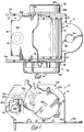
- FIGS. 1-3 there is shown a seat belt retractor 12 which embodies an anti-rattle or rattle suppressor system of the present invention.
- Seat belt retractors which are now required in all passenger cars, have certain basic elements which are typically a source of annoying rattles as vibration occurs in some of the constituent parts.
- the parts involved relate to the inertia device and the ratchet mechanism included to prevent protraction of the seat belt in an emergency situation as when the inertia device operates on the ratchet to prevent such seat belt protraction.
- the seat belt retractor 12 includes a U-shaped frame 14 which has parallel spaced sidewalls or side plates 14a and 14b which are interconnected by base portion 14c.
- the base portion is formed with openings such as 14d, shown in FIG. 2, to facilitate the mounting of the seat belt retractor 12 in the passenger compartment of an automobile.
- the reel 16 includes a shaft 16a which is journaled for rotation about its axis in the side plates 14a and 14b.
- the reel 16 is also provided with ratchet wheels 20 which are secured to and rotate with the shaft 16a.
- the ratchet wheels 20, which are conventional in form, are best shown in dotted lines in FIG. 3, and include a plurality of ratchet teeth 20a.
- the ratchet wheels 20 form a part of a ratchet mechanism 22 which also includes a locking pawl 24 which is mounted for limited pivotal movement in the side plates 14a and 14b on a shaft 24a. As illustrated in FIG. 2, the pawl extends between the side plates 14a and 14b having oppositely projecting ears 24b which extend outwardly beyond the side plates 14a and 14b and have edges 24c which are adapted to engage the teeth 20a of the ratchet wheels 20 to prevent counterclockwise rotation of the wheel as viewed in FIGS. 1 and 3.
- the locking pawl 24 is formed with a plate portion 24d, as shown in FIG. 2, extending to the left of the transversely extending shaft 24a.
- the underside of the plate portion 24d is engaged at its midpoint by an inertial device 26.
- the inertial device 26 is conventional and is intended to actuate the ratchet mechanism 22 in emergency situations such as will involve sudden acceleration or deceleration to cause the locking pawl 24 to engage the ratchet wheels 20 preventing further protraction of the seat belt 18.
- the pawl 24 When driving over bumps or rough roads the pawl 24 may pivot and strike ratchet teeth, causing rattling.
- the inertial device 26 is basically a pendulum mechanism including a weight 26a carried by the lower end of a shaft 26b which hangs from a disc 26c.
- the disc 26c rests on an annular support 26d having an opening through the shaft 26b extends.
- the weight 26a is displaced from its central position with shaft 26b disposed vertically, the disc 26c inclines from the horizontal and forces the locking pawl 24 clockwise in such emergency situations.
- the structure and function of the inertial device 26 are entirely conventional.
- the seat belt retractor 12 is provided with a rattle suppression device 28 which is mounted on the outside of the U-shaped frame 14 on the side plate 14a, as shown in FIG. 2.
- a rattle suppression device 28 which is mounted on the outside of the U-shaped frame 14 on the side plate 14a, as shown in FIG. 2.
- the belt retraction mechanism 29 which consists of a spring 29a mounted within a housing 29b, the spring being a helical spring which biases the reel 16 in a direction to retract the seat belt 18.
- the particular type of retraction mechanism employed is not significant and has no bearing on the present invention.
- a single retraction spring might be employed or several springs might be used to apply selectively varying tensions to the seat belt 18.
- the present invention is concerned with noise suppression with respect to the ratchet mechanism 22.
- the rattle suppression device 28 serves to apply a biasing force on the ratchet mechanism 22 during periods when the seat belt 18 is entirely retracted or only slightly protracted to the extent that it would not be sufficiently protracted to be in use by a vehicle occupant.
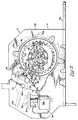
- the rattle suppression device 28 includes an outer cup-shaped housing member 30 and an inner cup-shaped housing member 32.
- the inner housing member 32 is secured to the outside surface of the side plate 14a of the frame 14, as shown in FIG. 5. Suitable fasteners secure the housing member 32 against the side plate 14a thereby forming an inner chamber 34 into which the shaft 16a of the reel 16 extends.
- One of the ears 24b of the locking pawl 24 also extends into the inner chamber 34.
- the side plate 14b is formed with an opening or cutout 35 through which the ear 24b extends into the chamber 34.
- the inner housing member 32 is formed with a peripheral wall 32a which surrounds a central wall portion 32b.
- the central wall portion 32b is provided with several openings, one being a centrally located opening 32c through which the reel shaft 16a extends as shown in FIG. 5.
- the outer end of the reel shaft 16a is received within a gear housing or outer chamber 36 formed by the outer housing member 30 and the central wall portion 32b of the inner housing member 32.
- the outer housing member 30 is secured to the inner housing member 32 by means of fasteners, not shown, to form the gear housing or outer chamber 36.
- the rattle suppression device 28 includes two major components which are a planetary gear system 38 disposed primarily in the chamber 36 and a pawl control mechanism 40 which is located partially within chamber 36 and partially within chamber 34.
- the planetary gear mechanism 38 is directly connected to the reel shaft 16a and provides means for actuating the rattle suppression device 28 in response to a predetermined extension or protraction of the seat belt 18 from the reel 16.
- the pawl control mechanism 40 is arranged to be actuated by the planetary gear mechanism 38 and to operate directly on the locking pawl 24.
- the planetary gear mechanism 38 includes a sun gear 42 which is secured to the outer end of the reel shaft 16a as best shown in FIG. 5.
- the end of the reel shaft 16a is formed with a reduced diameter portion 16c which extends through the opening 32c in the wall portion 32b as shown in FIG. 5.
- the sun gear 42 is keyed to the shaft 16a and is, therefore, driven by the reel 16.
- the planetary gear mechanism 38 also includes a pair of planet gears 46 and 48 shown in FIG. 3.
- the planet gears 46 and 48 are driven by the sun gear 42 and also engage an internal gear 50, which is formed integrally with the central wall portion 32b of the inner housing member 32. As shown in FIG. 5, the internal gear 50 is on the outer surface of the wall portion 32b and, therefore, within the outer chamber 36.
- the planet gears 46 and 48 are driven by the sun gear 42 which engage the internal gear 50 and rotate around the chamber 36 as the shaft 16a rotates.
- the planet gears 46 and 48 are confined between the wall of the outer housing member 30 and the wall portion 32b of the inner housing member 32.
- the pawl control mechanism 40 is located in the chambers 34 and 36 and includes an actuating means, preferably in the form of an activating or actuating lever 52, and a blockout means, preferably in the form of a lever 54.
- the actuating lever being disposed in the outer chamber 36 and the blockout lever being disposed in the inner chamber 34.
- a pin 52a which extends laterally from the actuating lever 52 as best shown in FIG. 8.
- the pin 52a is provided with a flatted portion 52b which is received within a correspondingly shaped opening 54a in the blockout lever 54 so as to secure the levers 52 and 54 together so that they rotate as a unit.
- the pin 52a is formed with an undercut portion 52f which receives a flexible wall 54e to lock the actuating lever 52 and the blockout lever 54 in assembled relation.
- the wall 54e is angled to permit its easy deflection when the pin 52a is inserted into opening 54a. when the wall 54e is received in the undercut portion 52f, it resumes its upright position seated firmly in the undercut portion 52f.
- the central wall portion 32b of the inner housing member 32 is formed with an opening 32d through which the pin 52a extends and which serves to journal the pawl control mechanism 40 with respect to the inner housing member 32.
- the actuating lever 52 is somewhat V-shaped including legs 52c and 52d, which extend from a central hub portion 52e. As best shown in FIG. 3, the legs 52c and 52d extend somewhat tangentially with respect to the hub portion 52e.
- the purpose of the planetary gear mechanism 38 is to provide means for controlling the rattle suppression device 28 in response to the protraction of a certain length of the seat belt 18.
- the planetary gear mechanism 38 is connected and driven by the shaft 16a of the reel 16.
- the pawl control mechanism 40 there is included within the outer chamber 36 a pair of actuating plungers 56 and 58.
- the plungers 56 and 58 are mounted in guide walls 59, formed integrally with the central wall portion 32b to guide the plungers 56 and 58 for rectilinear movement along lines which are radial with respect to the axis of the sun gear 42 and a reel shaft 16a.
- the central wall portion 32b is formed with elongated slots 32f which receive projections from the adjacent surfaces of the plungers 56 and 58 to limit the extent of rectilinear sliding movement of the plungers between the guide walls 59.
- the outer housing member 30 slidably engages the plungers 56 and 58 to prevent their outward displacement from the position between guide walls 59.
- the plungers 56 and 58 have flat inner ends 56a and 58a which are adapted to be engaged by portions of the planet gears 46 and 48 and rounded outer ends 56b and 58b which are adapted to engage the legs 52c and 52d of the actuating lever 52.
- the planet gear 46 is formed with an extension bar 46a which is aligned to engage the flatted end 56a of the plunger 56 and urge it radially outwardly when the projection 46a becomes aligned with the plunger 56.
- the planet gear 48 includes a projection 48a, as shown in FIG. 3, which is positioned to engage the plunger 58 when the planet gear 48 progresses around the internal gear 50 to the proper position.
- the projections 46a and 48a are disposed outwardly of the internal gear 50 and the sun gear 42 so that the projections 46a and 48a do not interfere with the gear teeth on the sun gear 42 or the internal gear 50.
- the projection 48a of the planet gear 48 is engaged with the plunger 58 and urges it to its outermost position as shown in FIG. 4.
- the planet gear 48 moves around counterclockwise along the internal gear 50 as shown in FIG. 4.
- the planet gear 46, with its projection 46a arrives at the position shown in FIGS. 3 and 6 when the plunger 56 is then forced outwardly radially to the position shown in FIG. 3, thereby rotating the actuating lever 52 to the position shown in FIG. 3.
- the blockout lever 54 includes a pawl engaging leg 54b and a spring support leg 54c.
- the spring support leg 54c has a lateral projection 54d which receives one end of a biasing spring 60, as shown in FIGS. 7 and 8.
- the end of the spring 60, remote from the blockout lever 54, is received on a projection 62 which extends inwardly from the central wall portion 32b of the inner housing member 32, as shown in FIG. 5.
- the spring 60 is shown as being V-shaped and having formed ends 60a and 60b which are received on the projection 54d and the projection 62 respectively as shown in FIG. 8.
- the purpose of the spring 60 is to bias the pawl control mechanism 40 in either of two directions.
- the projection 54d is located between the axis of the actuating lever pin 52a and the projection 62 so that there is a over-center movement causing the spring 60 to urge the pawl control mechanism 40 in a clockwise direction in one instance and in a counterclockwise direction in another instance.
- the spring 60 tends to rotate the pawl control mechanism 40 counterclockwise while as shown in FIG. 3 the spring 60 tends to rotate the pawl control mechanism 40 in a clockwise direction.
- the result of this over-center spring action is that the pawl control mechanism tends to remain in the position to which it has been urged by one or the other of the plungers 56 or 58.
- the purpose of the pawl control mechanism as alluded to above is to apply a force on the locking pawl 24 during a certain portion of the protraction cycle of the seat belt 18.
- the inertial device 26 which is basically intended to block the belt protraction movement of the reel 16 in an emergency situation such as a collision.
- the seat belt is protracted to a sufficient extent to be in use by a passenger, it would be advantageous to immobilize the parts of the inertial device and the locking pawl which tend to rattle or create noise as a consequence of the normal vibration encountered in an automobile.
- the locking pawl 24 be utilized to immobilize the inertial device 26 during this period when neither the locking pawl or the inertial device can serve any useful function. While the locking pawl 24 is normally biased by gravity to the position out of engagement with the ratchet wheels 20 and into engagement with the inertial device 26, the locking pawl 24 and the inertial device 26 are still subject to the rattling and noise generation problems discussed above.
- the blockout lever 54 is adapted to engage the ratchet-engaging ear 24b and urge the locking pawl 24 in a counterclockwise direction as shown by the arrow in FIG. 4.
- This counterclockwise urging is accomplished by the plunger 58 which at its outer rounded end 58b engages the leg 52d of the actuating lever 52, thereby positioning the pawl control mechanism 40 so that the spring 60 biases the pawl control mechanism 40 in a counterclockwise direction as shown in FIG. 4, whereby the blockout lever 54 with its leg 54b engages the locking pawl 24 and rotates it counterclockwise as shown in FIG. 4.
- the plunger 56 Upon protraction of a sufficient amount of seat belt 18 to cause the planetary gear mechanism 38 to progress to the position shown in FIG. 3, the plunger 56 is then forced outwardly with its rounded outer end 56b engaging against the leg 52c of the actuating lever 52, causing the pawl control mechanism 40 to rotate clockwise to the position shown in FIG. 3, at which time the leg 54b of the blockout lever 54 is moved away from the locking pawl 24 to the position shown in FIG. 1, leaving sufficient clearance for the inertial device 26 to rotate the locking pawl 24 into engagement with the ratchet wheels 20.
- the rattle suppression device 28 provides a simple and effective means for immobilizing the locking pawl and the inertial device of a seat belt retractor during a period in which the seat belt 18 is either not protracted or is only protracted a minimal amount.
- seat belt retractors are not in use in spite of the fact that the vehicle in which they are installed is moving and subjected to vibration.
- the seat belts of passengers are not in use since the driver is alone in the vehicle. In all such instances it is desirable to maintain the unused seat belts in as quiet a condition as possible.
- the present invention makes possible, through a provision of a small number of inexpensive plastic parts, means restraining the parts of the emergency locking mechanism against movement and vibration until such time as the seat belt is protracted sufficiently to indicate it is being used by some passenger in the vehicle.
Applications Claiming Priority (2)
| Application Number | Priority Date | Filing Date | Title |
|---|---|---|---|
| US79571991A | 1991-11-21 | 1991-11-21 | |
| US795719 | 1991-11-21 |
Publications (2)
| Publication Number | Publication Date |
|---|---|
| EP0543520A1 true EP0543520A1 (de) | 1993-05-26 |
| EP0543520B1 EP0543520B1 (de) | 1995-04-26 |
Family
ID=25166272
Family Applications (1)
| Application Number | Title | Priority Date | Filing Date |
|---|---|---|---|
| EP92310002A Expired - Lifetime EP0543520B1 (de) | 1991-11-21 | 1992-11-02 | Sicherheitsgurt-Aufroller mit Klypengeräusch-Beseitigungsvorrichtung |
Country Status (5)
| Country | Link |
|---|---|
| US (1) | US5358192A (de) |
| EP (1) | EP0543520B1 (de) |
| JP (1) | JP3205610B2 (de) |
| KR (1) | KR930009833A (de) |
| DE (1) | DE69202228T2 (de) |
Cited By (6)
| Publication number | Priority date | Publication date | Assignee | Title |
|---|---|---|---|---|
| EP0669233A2 (de) * | 1994-02-09 | 1995-08-30 | Trw Vehicle Safety Systems Inc. | Sicherheitsgurtaufroller |
| EP0806326A2 (de) * | 1996-05-06 | 1997-11-12 | TRW Occupant Restraint Systems GmbH | Gurtaufroller für Fahrzeugsicherheitsgurte |
| DE19732454A1 (de) * | 1997-07-29 | 1999-02-18 | Autoliv Dev | Selbstsperrender Gurtaufroller mit Retractor-Umschaltung |
| US6499554B1 (en) * | 1999-08-06 | 2002-12-31 | Hideaki Yano | Seat belt retractor |
| EP2944520A1 (de) * | 2009-07-21 | 2015-11-18 | Key Safety Systems, Inc. | Gurtaufroller für einen Fahrzeugsicherheitsgurt |
| DE10360032B4 (de) * | 2003-12-19 | 2020-06-18 | Trw Automotive Gmbh | Gurtaufroller für einen Fahrzeug-Sicherheitsgurt |
Families Citing this family (3)
| Publication number | Priority date | Publication date | Assignee | Title |
|---|---|---|---|---|
| KR100460002B1 (ko) * | 1998-01-03 | 2005-01-17 | 주식회사 새 한 | 드라이감이 우수한 방모조 폴리에스터 이수축 혼섬사 |
| US7874955B2 (en) * | 2007-09-28 | 2011-01-25 | Patterson Bicycle Transmission, Llc | Bicycle transmission system |
| US20110088366A1 (en) * | 2009-10-16 | 2011-04-21 | Alton Graetz | Rotary raking or sweeping implement |
Citations (6)
| Publication number | Priority date | Publication date | Assignee | Title |
|---|---|---|---|---|
| US3831878A (en) * | 1973-05-21 | 1974-08-27 | Gen Motors Corp | Restraint belt retractor |
| US4171782A (en) * | 1977-12-29 | 1979-10-23 | The Firestone Tire & Rubber Company | Apparatus and process for dead zone control in safety belt retractors |
| US4509706A (en) * | 1983-05-10 | 1985-04-09 | Allied Corporation | Safety belt system with tension eliminating mechanism |
| US4726539A (en) * | 1985-10-16 | 1988-02-23 | General Safety Corporation | Dual mode seat belt retractor assembly |
| DE8803659U1 (de) * | 1987-03-18 | 1988-07-07 | Takata Corp., Tokio/Tokyo, Jp | |
| EP0351551A2 (de) * | 1988-07-16 | 1990-01-24 | Bayerische Motoren Werke Aktiengesellschaft, Patentabteilung AJ-3 | Sicherheitsgurtanordnung an einem neigungsverstellbaren Kraftfahrzeugsitz |
Family Cites Families (9)
| Publication number | Priority date | Publication date | Assignee | Title |
|---|---|---|---|---|
| DE2351551A1 (de) * | 1973-10-13 | 1975-04-30 | Walter Battermann | Elastisches baulager |
| US4729523A (en) * | 1984-06-11 | 1988-03-08 | Kabushiki Kaisha Tokai-Rika-Denki-Seisakusho | Locking mechanism for webbing retractor |
| JPH0330211Y2 (de) * | 1985-03-29 | 1991-06-26 | ||
| JPS6247462U (de) * | 1985-09-13 | 1987-03-24 | ||
| JPS6274063U (de) * | 1985-10-30 | 1987-05-12 | ||
| US4749142A (en) * | 1985-12-27 | 1988-06-07 | Kabushiki Kaisha Tokai-Rika-Denki-Seisakusho | Webbing retractor |
| US4809926A (en) * | 1986-06-21 | 1989-03-07 | Nippon Seiko Kabushiki Kaisha | Webbing retractor |
| JPH0732293Y2 (ja) * | 1988-10-07 | 1995-07-26 | 株式会社東海理化電機製作所 | ウエビング巻取装置 |
| US5232176A (en) * | 1991-05-03 | 1993-08-03 | Takata, Inc. | Noise suppressor for seat belt retractor |
-
1992
- 1992-11-02 EP EP92310002A patent/EP0543520B1/de not_active Expired - Lifetime
- 1992-11-02 DE DE69202228T patent/DE69202228T2/de not_active Expired - Fee Related
- 1992-11-20 KR KR1019920021929A patent/KR930009833A/ko not_active Application Discontinuation
- 1992-11-24 JP JP31360692A patent/JP3205610B2/ja not_active Expired - Fee Related
-
1993
- 1993-09-17 US US08/123,579 patent/US5358192A/en not_active Expired - Fee Related
Patent Citations (6)
| Publication number | Priority date | Publication date | Assignee | Title |
|---|---|---|---|---|
| US3831878A (en) * | 1973-05-21 | 1974-08-27 | Gen Motors Corp | Restraint belt retractor |
| US4171782A (en) * | 1977-12-29 | 1979-10-23 | The Firestone Tire & Rubber Company | Apparatus and process for dead zone control in safety belt retractors |
| US4509706A (en) * | 1983-05-10 | 1985-04-09 | Allied Corporation | Safety belt system with tension eliminating mechanism |
| US4726539A (en) * | 1985-10-16 | 1988-02-23 | General Safety Corporation | Dual mode seat belt retractor assembly |
| DE8803659U1 (de) * | 1987-03-18 | 1988-07-07 | Takata Corp., Tokio/Tokyo, Jp | |
| EP0351551A2 (de) * | 1988-07-16 | 1990-01-24 | Bayerische Motoren Werke Aktiengesellschaft, Patentabteilung AJ-3 | Sicherheitsgurtanordnung an einem neigungsverstellbaren Kraftfahrzeugsitz |
Cited By (10)
| Publication number | Priority date | Publication date | Assignee | Title |
|---|---|---|---|---|
| EP0669233A2 (de) * | 1994-02-09 | 1995-08-30 | Trw Vehicle Safety Systems Inc. | Sicherheitsgurtaufroller |
| EP0669233A3 (de) * | 1994-02-09 | 1996-11-27 | Trw Vehicle Safety Systems | Sicherheitsgurtaufroller. |
| EP0806326A2 (de) * | 1996-05-06 | 1997-11-12 | TRW Occupant Restraint Systems GmbH | Gurtaufroller für Fahrzeugsicherheitsgurte |
| EP0806326A3 (de) * | 1996-05-06 | 2000-09-27 | TRW Occupant Restraint Systems GmbH & Co. KG | Gurtaufroller für Fahrzeugsicherheitsgurte |
| DE19732454A1 (de) * | 1997-07-29 | 1999-02-18 | Autoliv Dev | Selbstsperrender Gurtaufroller mit Retractor-Umschaltung |
| US6062502A (en) * | 1997-07-29 | 2000-05-16 | Autoliv Development Ab | Self-locking safety belt device with retractor switching function |
| DE19732454C2 (de) * | 1997-07-29 | 2002-02-21 | Autoliv Dev | Selbstsperrender Gurtaufroller mit Retractor-Umschaltung |
| US6499554B1 (en) * | 1999-08-06 | 2002-12-31 | Hideaki Yano | Seat belt retractor |
| DE10360032B4 (de) * | 2003-12-19 | 2020-06-18 | Trw Automotive Gmbh | Gurtaufroller für einen Fahrzeug-Sicherheitsgurt |
| EP2944520A1 (de) * | 2009-07-21 | 2015-11-18 | Key Safety Systems, Inc. | Gurtaufroller für einen Fahrzeugsicherheitsgurt |
Also Published As
| Publication number | Publication date |
|---|---|
| DE69202228T2 (de) | 1995-08-31 |
| KR930009833A (ko) | 1993-06-21 |
| JPH05305856A (ja) | 1993-11-19 |
| US5358192A (en) | 1994-10-25 |
| EP0543520B1 (de) | 1995-04-26 |
| DE69202228D1 (de) | 1995-06-01 |
| JP3205610B2 (ja) | 2001-09-04 |
Similar Documents
| Publication | Publication Date | Title |
|---|---|---|
| KR100871570B1 (ko) | 시트벨트의 웨빙로킹방지장치 | |
| US5529258A (en) | Secondary locking mechanism for retractor with pretensioner | |
| US4437623A (en) | Integrated weblocker with program pawl retractor | |
| US5934596A (en) | Automatic locking retractor with timing clutch mechanism | |
| US4244600A (en) | Deactivatable locking retractor for vehicle seat belt systems | |
| WO2020052396A1 (zh) | 安全带卷收器和安全带组件 | |
| US4065072A (en) | Seat belt retractor with winding prevention mechanism | |
| US6871813B2 (en) | Vehicular seatbelt retractor | |
| WO2020052400A1 (zh) | 安全带卷收器和安全带组件 | |
| US7377463B2 (en) | Noise reducing seat belt retractor | |
| US5333906A (en) | Seat belt retractor | |
| EP0543520B1 (de) | Sicherheitsgurt-Aufroller mit Klypengeräusch-Beseitigungsvorrichtung | |
| US5820060A (en) | Seat belt retractor | |
| US4165844A (en) | Dual tension safety belt | |
| CN109476278B (zh) | 安全带伸缩器 | |
| JPS6253270A (ja) | シ−トベルトのリトラクタ−リ−ル | |
| GB2264329A (en) | Seat belt buckle means | |
| US4940193A (en) | Safety belt retractor with improved dampening | |
| JP2003212085A (ja) | シートベルト用リトラクター | |
| US4771854A (en) | Belt winding brake for passive belt retractor | |
| US5301893A (en) | Seat belt retractor having a noise suppression mechanism with a blockout cam | |
| US5507449A (en) | Seat belt retractor with noise suppression | |
| US5312066A (en) | Restraint belt retractor | |
| US4429841A (en) | Emergency locking device for safety belt retractor | |
| US4027829A (en) | Flywheel and clutch mechanism for safety belt retractor |
Legal Events
| Date | Code | Title | Description |
|---|---|---|---|
| PUAI | Public reference made under article 153(3) epc to a published international application that has entered the european phase |
Free format text: ORIGINAL CODE: 0009012 |
|
| AK | Designated contracting states |
Kind code of ref document: A1 Designated state(s): DE FR GB |
|
| 17P | Request for examination filed |
Effective date: 19930503 |
|
| 17Q | First examination report despatched |
Effective date: 19940119 |
|
| GRAA | (expected) grant |
Free format text: ORIGINAL CODE: 0009210 |
|
| AK | Designated contracting states |
Kind code of ref document: B1 Designated state(s): DE FR GB |
|
| REF | Corresponds to: |
Ref document number: 69202228 Country of ref document: DE Date of ref document: 19950601 |
|
| ET | Fr: translation filed | ||
| PGFP | Annual fee paid to national office [announced via postgrant information from national office to epo] |
Ref country code: FR Payment date: 19951030 Year of fee payment: 4 |
|
| PLBE | No opposition filed within time limit |
Free format text: ORIGINAL CODE: 0009261 |
|
| STAA | Information on the status of an ep patent application or granted ep patent |
Free format text: STATUS: NO OPPOSITION FILED WITHIN TIME LIMIT |
|
| 26N | No opposition filed | ||
| PG25 | Lapsed in a contracting state [announced via postgrant information from national office to epo] |
Ref country code: GB Effective date: 19961102 |
|
| GBPC | Gb: european patent ceased through non-payment of renewal fee |
Effective date: 19961102 |
|
| PG25 | Lapsed in a contracting state [announced via postgrant information from national office to epo] |
Ref country code: FR Effective date: 19970731 |
|
| REG | Reference to a national code |
Ref country code: FR Ref legal event code: ST |
|
| PGFP | Annual fee paid to national office [announced via postgrant information from national office to epo] |
Ref country code: DE Payment date: 19980430 Year of fee payment: 6 |
|
| PG25 | Lapsed in a contracting state [announced via postgrant information from national office to epo] |
Ref country code: DE Free format text: LAPSE BECAUSE OF NON-PAYMENT OF DUE FEES Effective date: 19990901 |