EP0542657A1 - Universal communications interface adaptable for a plurality of interface standards - Google Patents
Universal communications interface adaptable for a plurality of interface standards Download PDFInfo
- Publication number
- EP0542657A1 EP0542657A1 EP92480144A EP92480144A EP0542657A1 EP 0542657 A1 EP0542657 A1 EP 0542657A1 EP 92480144 A EP92480144 A EP 92480144A EP 92480144 A EP92480144 A EP 92480144A EP 0542657 A1 EP0542657 A1 EP 0542657A1
- Authority
- EP
- European Patent Office
- Prior art keywords
- binary signals
- interface
- cable
- signals
- communications processor
- Prior art date
- Legal status (The legal status is an assumption and is not a legal conclusion. Google has not performed a legal analysis and makes no representation as to the accuracy of the status listed.)
- Granted
Links
Images


Classifications
-
- H—ELECTRICITY
- H04—ELECTRIC COMMUNICATION TECHNIQUE
- H04L—TRANSMISSION OF DIGITAL INFORMATION, e.g. TELEGRAPHIC COMMUNICATION
- H04L12/00—Data switching networks
- H04L12/28—Data switching networks characterised by path configuration, e.g. LAN [Local Area Networks] or WAN [Wide Area Networks]
- H04L12/2854—Wide area networks, e.g. public data networks
- H04L12/2856—Access arrangements, e.g. Internet access
- H04L12/2858—Access network architectures
-
- H—ELECTRICITY
- H04—ELECTRIC COMMUNICATION TECHNIQUE
- H04L—TRANSMISSION OF DIGITAL INFORMATION, e.g. TELEGRAPHIC COMMUNICATION
- H04L9/00—Cryptographic mechanisms or cryptographic arrangements for secret or secure communications; Network security protocols
- H04L9/40—Network security protocols
Definitions
- the present invention relates to interfaces in a communication network and more particularly to an interface subsystem for use in a data or telecommunications network employing the interchange of binary signals, the interface subsystem being adaptable to a plurality of electrical interface standards in the industry, such as EIA-232-D, and CCITT Recommendations V.35 and X.21.
- Virtually all communications machines that use telecommunications links employ one of a plurality of standard electrical interfaces whose specifications have been developed by the Electronics Industries Association (EIA) in the United States and by the International Brass and Telephone Consultative Committee (CCITT) in other countries of the world.
- the EIA and CCITT interfaces specify voltage levels whereby control and data signals are exchanged between two business machines, such as data terminal equipment (DTE) and a data circuit-terminating equipment (DCE), in two-level form. All data signals are sent across the interface, from a transmission medium, such as a cable, using a predetermined electrical interface having a two-level, bit-by-bit serial signaling convention.
- the processing systems of a DTE and a DCE can not, in most cases, process the communication signals having parameters conforming to the predetermined electrical interface, the signals must be converted to a different voltage level so that they may be processed.
- an interface circuit is utilized by the DTE and DCE for converting the communication signals to levels usable by each business machine.
- the interface circuit converts the signals to be transmitted by each business machine to levels conforming to the predetermined electrical interface.
- EIA RS-422-A specifies that the entire common mode voltage (V cm ) range for a receiver in a DTE or DCE shall be +7 Volts (V) to -7V and that the receiver shall operate with a maximum differential signal of 6V applied across its terminals.
- EIA-232-D specifies a range of +15V to -15V and also specifies the circuit should not fail for voltages of +30V to -30V.
- V.35 defines the input voltage for the receiver to be common mode +2V to -2V and differential +0.66V to -0.66V.
- DTEs and DCEs each having number of interface boards, each corresponding to a particular electrical interface standard, kept available for being switched into and out of the respective DTE or DCE depending upon which electrical interface standard is being implemented at the time.
- this requires that particular boards be kept available at the DTE or DCE. These boards, while not being used, are left idle and can be easily lost or damaged.
- this problem is solved by having a separate cable for each of the interface standards and by routing the signals, depending upon which standard is being used, to a corresponding receiver or set of receivers.
- a common connector is used at the interchange interface.
- a group of pins on that connector is dedicated to signals which are unique to the EIA-232-D interface standard. Those signals are routed to a particular receiver or set of receivers configured to receive those signals and convert them to transistor-transistor logic (TTL) level so that a communications processor in the DTE or DCE may process them.
- TTL transistor-transistor logic
- Another group of pins are dedicated to those signals unique to the RS-422-A electrical interface standard.
- those RS-422-A signals are routed to receiver(s) configured to convert those signals to TTL level.
- receiver(s) configured to convert those signals to TTL level.
- a switch is utilized to switch the appropriate receiver outputs to the communications processor. Cable identification (ID) bits in the cable are used by the switch to identify which electrical interface is being used. This method, however, consumes too much board and connector space and requires unneeded components.
- the interface subsystem of the present invention comprises a universal interface card or unit for use with any of a plurality of electrical interface standards, in particular, EIA-232-D and CCITT Recommendations V.35 and X.21.
- the interface subsystem further comprises a cable selected from a set of cables for use with the particular standard being utilized.
- the particular cable (there is one cable for each standard to be interfaced) has passive components therein for preconditioning the signals so that the signals are within a voltage level window suitable for the universal interface unit.
- the universal interface unit comprises an input/output port for receiving the preconditioned signals utilizing common pins among the interface standards, i.e., pins on the connector at the port are shared by the interface standards rather than being dedicated to groups of signals of each of the interface standards.
- the preconditioned signals are routed to receivers for converting the signals to TTL level for processing by a communications processor. All of the balanced (differential) signals are routed to differential receivers while the single-ended signals, if any, may be routed to the differential receivers, if any are available, or, alternatively, may be routed to a group of single-ended receivers.
- the present invention provides a more efficient interface subsystem for interfacing one of a plurality of electrical interface standards by utilizing a universal interface unit for receiving the signals conforming to the various interface standards at common pin designations.
- One cable selected from a set of cables is connected to the universal interface unit for preconditioning the signals and conveying the signals to the universal interface unit.
- the particular cable selected corresponds to the electrical interface to be used. In this manner, no additional circuitry, such as dedicated receivers for the electrical interfaces or switches, are not required. In addition, dedicated interface cards for the particular electrical interfaces are unnecessary.
- FIG. 1 is a simplified block diagram of a data or telecommunications network employing the present invention.
- FIG. 2 is a simplified block diagram of the universal interface unit of the present invention.
- FIG. 3 is a schematic diagram of the universal interface unit of the present invention.
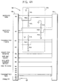
- FIG. 4A is a schematic diagram of the standard-specific cable for the CCITT V.35 electrical interface.
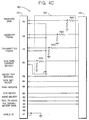
- FIG. 4B is a schematic diagram of the standard-specific cable for the CCITT X.21 electrical interface.
- FIG. 4C is a schematic diagram of the standard-specific cable for the EIA-232-D electrical interface
- FIG. 1 illustrates, in block diagram form, a simplified data or communications network 10 having a data terminal equipment (DTE) 12, a data circuit-terminating equipment (DCE) 14 and an interconnecting cable 16 extending therebetween.
- DTE data terminal equipment
- DCE data circuit-terminating equipment
- the network 10 is shown having only two nodes (DTE 12 and DCE 14), the network 10 can have any number of nodes, limited only by logical protocol and physical constraints, without having any effect on the functionality of the present invention.
- information is transferred between the functional units, DTE 12 and DCE 14, by means of data transmission according to a logical protocol such as, for example, the Synchronous Data Link Control (SDLC) protocol.
- SDLC Synchronous Data Link Control
- the data transfer takes place over cable 16 between DTE 12 and DCE 14.
- cable 16 has connectors 17 for connecting to the functional units (DTE 12 and DCE 14).
- cable 16 has a preconditioning unit 15 for preconditioning the signals being transferred between the DTE 12 and the DCE 14.
- Each universal interface unit 10 comprises an input/output connector 20 for connecting to the corresponding cable connector 17, a communications processor 22 for processing the transferred information, a receiver (or receivers) 24 for converting the received information to a level that the processor is able process (for example, transistor-transistor logic (TTL) level), and a line driver (or line drivers) 26 for driving the information over cable 16.
- TTL transistor-transistor logic
- the network 10 employs one of a plurality of standard electrical interfaces whose specifications have been developed by the Electronics Industries Association (EIA) and by the International Circuit and Telephone Consultative Committee (CCITT). Some of the more common standard electrical interfaces employed are EIA-232-D, CCITT Recommendation X.21, and CCITT Recommendation V.35. These EIA and CCITT interfaces specify voltage levels whereby control and data signals are exchanged between business machines over a transmission medium in two-level form.
- the universal interface unit 18 is used to interface with signals conforming to any of a plurality of the electrical interface standards without the need for switching between a number of dedicated receivers for signals conforming to the various interface standards.
- cable 16 is one of a set of cables configured to precondition signals prior to being received by the universal interface unit 18.
- Each particular cable is configured for preconditioning signals conforming to a particular electrical interface standard.
- one cable is configured to precondition signals conforming to EIA-232-D so that the universal interface unit 18 may properly receive the signals, while another cable is adapted to precondition signals conforming to CCITT Recommendation X.21 so that the universal interface unit 18 may properly receive those signals, and so forth.
- the universal interface unit 18 of the present invention is shown in a block diagram.
- the universal interface unit 18 comprises a connector 20 for being connected to the standard-specific cable 16, a receiver or receivers 24, a communications processor 22 and a driver or drivers 26.
- the universal interface unit 18 employs over-voltage protection and signal conditioning circuitry 25 for protecting the receiver 24 from an inordinately high input voltage due to a short circuit or the like and for providing some conditioning to the input signals, such as, for instance, removing the high frequency components from the signals.
- Cable identification bits 27 are routed to the communications processor 22 for identifying the particular standard-specific cable 16.
- the receiver 24 and driver 26 each comprise receivers and drivers for both balanced (differential) and single-ended signals.
- receiver 24 comprises balanced signal line receivers 28 and single-ended line receivers 30.
- driver 26 comprises balanced signal line drivers 32 and single-ended line drivers 34.
- received balanced signals 36 and received single-ended signals 38 are received by the appropriate receivers 28 and 30, respectively.
- transmitted balanced signals 40 and transmitted single-ended signals 42 are driven by the appropriate respective drivers 32 and 34.
- the received single-ended signals 38 may be received by the balanced signal line receivers 28 (one of the differential receiver inputs being tied to ground).
- the single-ended line receivers 30 are only needed to extent that there are no unused differential receiver line inputs for the particular electrical interface.
- the signals conforming to each of the different electrical interface standards are routed to and received by common receivers so that receivers are not dedicated to a particular interface standard.
- the universal interface unit 18 comprises balanced signal line receivers 28 having inputs for receiving four balanced, or differential, signal lines 36. Space allocated for these signal lines is indicated by the numerals 44, 46, 48, and 50 in interchange connector 20.
- the balanced signal lines 44, 46, 48, and 50 are routed through the protection and conditioning circuitry 25 to protect the line receivers 24 from an inordinately high input voltage and to provide some conditioning to the input signals.
- the universal interface unit 18 comprises single-ended line drivers 30 having inputs for receiving three single-ended lines 38. Space allocated for these signal lines is indicated by the numerals 52, 54, and 56 in interchange connector 20.
- the universal interface unit 18 comprises balanced line drivers 32 (V.35 driver 33 and X.21 driver 35), having outputs for driving two balanced signal lines 40, and single-ended line drivers 34, having outputs for driving four single-ended signal lines 42.
- Connector space allocated for these signal lines is indicated by the numerals 66 and 68 (for the balanced lines 40) and 58, 60, 62 and 64 (for single-ended lines 42).
- the remaining two lines are cable identification (ID) lines 43 for identifying to the communications processor 22 which cable is being utilized.
- Connector space allocated for the cable ID lines 43 is indicated by the numeral 27 on the interchange connector 20. It should be noted that the numbers used to indicate the allocated connector space for the particular signal lines are not actual connector pin numbers and that the actual connector pin numbers may be selected as desired.
- FIG. 4A CITT V.35
- FIG. 4B CITT X.21
- FIG. 4C EIA-232-D
- FIG. 4A illustrates the V.35 standard-specific cable 16A for use with signals conforming to the CCITT V.35 standard.
- Cable 16A is utilized to connect between the universal interface unit 18 and a DCE, for example, as shown in FIG. 1.
- Cable 16A comprises connectors 17A for connecting to the universal interface unit at one end and to the DCE at the other.
- the use of the allocated connector space is determined by the electrical interface standard utilized.
- the V.35 standard specifies three balanced signals, RECEIVED DATA, RECEIVER TIMING and TRANSMITTER TIMING, and three single-ended signals, READY FOR SENDING, DATA SET READY, and DCD DATA CARRIER DETECT, to be transmitted to the DTE.
- V.35 specifies a single balanced signal, TRANSMITTED DATA, and one single-ended signal, REQUEST TO SEND, to be transmitted by the DTE. These signals are routed to balanced line-allocated connector space 66 and single-ended-allocated connector space 58, respectively.
- Connector spaces 50, 60, 62, 64 and 68 are not used with the V.35-specific cable but are kept available for the other standards (X.21 and EIA-232-D) to be interfaced.
- Cable 16A further comprises a preconditioning unit 15A.
- Preconditioning unit 15A is utilized to precondition a portion of the signals being transmitted to the universal interface unit.
- the preconditioning unit 15A preconditions balanced signals RECEIVED DATA, RECEIVER TIMING and TRANSMITTER TIMING.
- the cable ID signal lines which are configured in a predetermined manner to identify the cable (one grounded, the other left floating)
- the remaining communication signals are fed directly through the cable 16A without any preconditioning.
- Preconditioning unit 15A comprises a plurality of resistors R1A and R2A, each resistor labeled R1A having a particular value and each resistor labeled R2A having another particular value.
- the resistors are configured so that R2A is connected between the complementary signal lines of each of the above-mentioned differential signals.
- a resistor having the value of R1A is connected between each complementary signal line and ground.
- the resistors act as a voltage divider so that the voltage value of each signal line is a fraction of the original voltage value when transmitted. In this way, the voltage level of the specific differential signal is within a "window" of acceptable voltage values for the receiver used in the universal interface unit.
- resistor R2A between each differential signal line provides a specified impedance so that the cable 16A may properly interface the universal interface unit and the DCE.
- the same universal interface unit is utilized and, therefore, is not shown in a figure. The only difference is the particular implementation of the unit, or, in particular, which of the available circuitry in the unit is utilized.
- the CCITT X.21 interface standard as with the CCITT V.35 standard, requires the use of three balanced received signals (RECEIVED DATA, RECEIVER TIMING and TRANSMITTER TIMING). But, in contrast to the CCITT V.35 standard, no single-ended signals are received or transmitted by the DTE. Therefore, single-ended receivers 30 and single-ended drivers 34 are not utilized. These signals are appropriately terminated in the corresponding CCITT X.21 standard-specific cable.
- the CCITT X.21 standard-specific cable 16B is shown in FIG. 4B.
- the X.21 cable 16B comprises a preconditioning unit 15B having a plurality of resistors R1B and R2B tied to the balanced signal lines.
- the resistors are used for altering the voltage values of the signals so that the values are within the window of acceptable voltage values for the universal interface unit.
- the resistors provide each balanced signal line with the specified impedance for properly interfacing with the universal interface unit.
- the values of the resistors are different from those of the V.35 cable and are determined by the window of acceptable voltage values of the balanced signal line receiver 28 (FIG. 3) chosen for the universal interface unit.
- the remaining unused space on connector 17B i.e., reference numbers 50, 52, 54, 56, 58, 60, 62, 64, and 66, are allocated on the universal interface unit input/output port for signals conforming to other predefined electrical interface standards. Additionally, cable ID lines at connector space 27 are both terminated, indicating to the universal interface unit that an X.21 cable is being utilized.
- the EIA-232-D standard-specific cable 16C is shown in FIG. 4C.
- the EIA-232-D cable 16C uses a preconditioning unit 15C for preconditioning signals transmitted to the universal interface unit.
- Preconditioning unit 15C comprises a plurality of resistors R1C and R2C for altering the voltage values of the signals so that the values are within the window of acceptable voltage values for the universal interface unit and for providing proper impedance matching for the cable and the unit.
- no balanced signals need to be transmitted over the EIA-232-D cable.
- both the single-ended signal line receivers 30 and the balanced signal line receivers 28 (Fig. 3) are utilized to receive the single-ended signal lines. But, for the balanced signal line receivers 28 to operate properly, one of the complementary signals of each balanced signal input to the balanced signal line receiver 28 must be terminated to ground. This is accomplished in the cable 16C.
- the remaining unused space on connector 17C i.e., reference numbers 66 and 68, are allocated on the universal interface unit input/output port for signals conforming to other predefined electrical interface standards, in this case, the CCITT V.35 and CCITT X.21 standards.
- the present invention provides a more efficient interface subsystem for interfacing one of a plurality of electrical interface standards by utilizing a universal interface unit for receiving the signals conforming to the various interface standards at common pin designations.
- One cable selected from a set of cables is connected to the universal interface unit for preconditioning the signals and conveying the signals to the universal interface unit.
- the particular cable selected corresponds to the electrical interface to be used.
- additional circuitry such as dedicated receivers for the electrical interfaces or switches, are not required.
- dedicated interface cards for the particular electrical interfaces are unnecessary.
Landscapes
- Engineering & Computer Science (AREA)
- Computer Security & Cryptography (AREA)
- Computer Networks & Wireless Communication (AREA)
- Signal Processing (AREA)
- Communication Control (AREA)
Abstract
Description
- The present invention relates to interfaces in a communication network and more particularly to an interface subsystem for use in a data or telecommunications network employing the interchange of binary signals, the interface subsystem being adaptable to a plurality of electrical interface standards in the industry, such as EIA-232-D, and CCITT Recommendations V.35 and X.21.
- Virtually all communications machines that use telecommunications links employ one of a plurality of standard electrical interfaces whose specifications have been developed by the Electronics Industries Association (EIA) in the United States and by the International Telegraph and Telephone Consultative Committee (CCITT) in other countries of the world. The EIA and CCITT interfaces specify voltage levels whereby control and data signals are exchanged between two business machines, such as data terminal equipment (DTE) and a data circuit-terminating equipment (DCE), in two-level form. All data signals are sent across the interface, from a transmission medium, such as a cable, using a predetermined electrical interface having a two-level, bit-by-bit serial signaling convention.
- Because the processing systems of a DTE and a DCE can not, in most cases, process the communication signals having parameters conforming to the predetermined electrical interface, the signals must be converted to a different voltage level so that they may be processed. Normally, an interface circuit is utilized by the DTE and DCE for converting the communication signals to levels usable by each business machine. Similarly, the interface circuit converts the signals to be transmitted by each business machine to levels conforming to the predetermined electrical interface.
- A problem arises, however, where it is desired that a DTE or DCE be used with a number of different EIA and CCITT standards. For example, it may be desirable that a DTE or DCE be able to interface with EIA RS-422-A, EIA-232-D, and CCITT Recommendation V.35. Each of the three electrical interface standards has different defined voltage levels than each of the other electrical interface standards. For example, EIA RS-422-A specifies that the entire common mode voltage (Vcm) range for a receiver in a DTE or DCE shall be +7 Volts (V) to -7V and that the receiver shall operate with a maximum differential signal of 6V applied across its terminals. In contrast, EIA-232-D specifies a range of +15V to -15V and also specifies the circuit should not fail for voltages of +30V to -30V. Furthermore, V.35 defines the input voltage for the receiver to be common mode +2V to -2V and differential +0.66V to -0.66V. As a result, interface circuits cannot accommodate each of the standards with a common receiver as one receiver cannot accommodate the complete "window" of voltage levels specified by the various electrical interface standards.
- Presently, this problem is solved by DTEs and DCEs each having number of interface boards, each corresponding to a particular electrical interface standard, kept available for being switched into and out of the respective DTE or DCE depending upon which electrical interface standard is being implemented at the time. Obviously, this requires that particular boards be kept available at the DTE or DCE. These boards, while not being used, are left idle and can be easily lost or damaged.
- In other DTEs and DCEs, this problem is solved by having a separate cable for each of the interface standards and by routing the signals, depending upon which standard is being used, to a corresponding receiver or set of receivers. For example, a common connector is used at the interchange interface. A group of pins on that connector is dedicated to signals which are unique to the EIA-232-D interface standard. Those signals are routed to a particular receiver or set of receivers configured to receive those signals and convert them to transistor-transistor logic (TTL) level so that a communications processor in the DTE or DCE may process them. Another group of pins are dedicated to those signals unique to the RS-422-A electrical interface standard. Similarly, those RS-422-A signals are routed to receiver(s) configured to convert those signals to TTL level. The same is true for the V.35 standard and so forth. A switch is utilized to switch the appropriate receiver outputs to the communications processor. Cable identification (ID) bits in the cable are used by the switch to identify which electrical interface is being used. This method, however, consumes too much board and connector space and requires unneeded components.
- It is therefore the general object of the present invention to provide a more efficient interface subsystem for use with a business machine for use in a communication or data network, such as a DTE or DCE, which is able to interface with one of a plurality of electrical interface standards.
- The interface subsystem of the present invention comprises a universal interface card or unit for use with any of a plurality of electrical interface standards, in particular, EIA-232-D and CCITT Recommendations V.35 and X.21. The interface subsystem further comprises a cable selected from a set of cables for use with the particular standard being utilized. The particular cable (there is one cable for each standard to be interfaced) has passive components therein for preconditioning the signals so that the signals are within a voltage level window suitable for the universal interface unit.
- The universal interface unit comprises an input/output port for receiving the preconditioned signals utilizing common pins among the interface standards, i.e., pins on the connector at the port are shared by the interface standards rather than being dedicated to groups of signals of each of the interface standards. The preconditioned signals are routed to receivers for converting the signals to TTL level for processing by a communications processor. All of the balanced (differential) signals are routed to differential receivers while the single-ended signals, if any, may be routed to the differential receivers, if any are available, or, alternatively, may be routed to a group of single-ended receivers.
- Thus, the present invention provides a more efficient interface subsystem for interfacing one of a plurality of electrical interface standards by utilizing a universal interface unit for receiving the signals conforming to the various interface standards at common pin designations. One cable selected from a set of cables is connected to the universal interface unit for preconditioning the signals and conveying the signals to the universal interface unit. The particular cable selected corresponds to the electrical interface to be used. In this manner, no additional circuitry, such as dedicated receivers for the electrical interfaces or switches, are not required. In addition, dedicated interface cards for the particular electrical interfaces are unnecessary.
- While the technical description concludes with claims particularly pointing out and distinctly claiming that which is regarded as the present invention, details of a preferred embodiment of the invention may be more readily ascertained from the following technical description when read in conjunction with the accompanying drawings, where:
- FIG. 1 is a simplified block diagram of a data or telecommunications network employing the present invention.
- FIG. 2 is a simplified block diagram of the universal interface unit of the present invention.
- FIG. 3 is a schematic diagram of the universal interface unit of the present invention.
- FIG. 4A is a schematic diagram of the standard-specific cable for the CCITT V.35 electrical interface.
- FIG. 4B is a schematic diagram of the standard-specific cable for the CCITT X.21 electrical interface.
- FIG. 4C is a schematic diagram of the standard-specific cable for the EIA-232-D electrical interface
- FIG. 1 illustrates, in block diagram form, a simplified data or
communications network 10 having a data terminal equipment (DTE) 12, a data circuit-terminating equipment (DCE) 14 and aninterconnecting cable 16 extending therebetween. Although thenetwork 10 is shown having only two nodes (DTE 12 and DCE 14), thenetwork 10 can have any number of nodes, limited only by logical protocol and physical constraints, without having any effect on the functionality of the present invention. - As in any communications network, information is transferred between the functional units,
DTE 12 and DCE 14, by means of data transmission according to a logical protocol such as, for example, the Synchronous Data Link Control (SDLC) protocol. In the present case, the data transfer takes place overcable 16 between DTE 12 and DCE 14. Like other communications cables,cable 16 hasconnectors 17 for connecting to the functional units (DTE 12 and DCE 14). In addition, however,cable 16 has a preconditioning unit 15 for preconditioning the signals being transferred between theDTE 12 and the DCE 14. - Connecting to and interfacing with the
communications cable 16 atconnectors 17 is auniversal interface unit 18 within theDTE 12 and the DCE 14. Eachuniversal interface unit 10 comprises an input/output connector 20 for connecting to thecorresponding cable connector 17, acommunications processor 22 for processing the transferred information, a receiver (or receivers) 24 for converting the received information to a level that the processor is able process (for example, transistor-transistor logic (TTL) level), and a line driver (or line drivers) 26 for driving the information overcable 16. - In addition to following a logical protocol, the
network 10 employs one of a plurality of standard electrical interfaces whose specifications have been developed by the Electronics Industries Association (EIA) and by the International Telegraph and Telephone Consultative Committee (CCITT). Some of the more common standard electrical interfaces employed are EIA-232-D, CCITT Recommendation X.21, and CCITT Recommendation V.35. These EIA and CCITT interfaces specify voltage levels whereby control and data signals are exchanged between business machines over a transmission medium in two-level form. - In accordance with the present invention, the
universal interface unit 18 is used to interface with signals conforming to any of a plurality of the electrical interface standards without the need for switching between a number of dedicated receivers for signals conforming to the various interface standards. - Further in accordance with the present invention,
cable 16 is one of a set of cables configured to precondition signals prior to being received by theuniversal interface unit 18. Each particular cable is configured for preconditioning signals conforming to a particular electrical interface standard. For example, one cable is configured to precondition signals conforming to EIA-232-D so that theuniversal interface unit 18 may properly receive the signals, while another cable is adapted to precondition signals conforming to CCITT Recommendation X.21 so that theuniversal interface unit 18 may properly receive those signals, and so forth. - Referring now to FIG. 2, the
universal interface unit 18 of the present invention is shown in a block diagram. As was discussed briefly above, theuniversal interface unit 18 comprises aconnector 20 for being connected to the standard-specific cable 16, a receiver orreceivers 24, acommunications processor 22 and a driver ordrivers 26. In addition, theuniversal interface unit 18 employs over-voltage protection andsignal conditioning circuitry 25 for protecting thereceiver 24 from an inordinately high input voltage due to a short circuit or the like and for providing some conditioning to the input signals, such as, for instance, removing the high frequency components from the signals.Cable identification bits 27 are routed to thecommunications processor 22 for identifying the particular standard-specific cable 16. - Because each electrical interface standard specifies different signal characteristics, the
receiver 24 anddriver 26 each comprise receivers and drivers for both balanced (differential) and single-ended signals. In particular,receiver 24 comprises balancedsignal line receivers 28 and single-endedline receivers 30. Similarly,driver 26 comprises balancedsignal line drivers 32 and single-endedline drivers 34. In this way, receivedbalanced signals 36 and received single-endedsignals 38 are received by theappropriate receivers balanced signals 40 and transmitted single-endedsignals 42 are driven by the appropriaterespective drivers signals 38 may be received by the balanced signal line receivers 28 (one of the differential receiver inputs being tied to ground). Thus, the single-endedline receivers 30 are only needed to extent that there are no unused differential receiver line inputs for the particular electrical interface. - In accordance with the present invention, the signals conforming to each of the different electrical interface standards are routed to and received by common receivers so that receivers are not dedicated to a particular interface standard. In particular, as shown in FIG. 3, the
universal interface unit 18 comprises balancedsignal line receivers 28 having inputs for receiving four balanced, or differential, signal lines 36. Space allocated for these signal lines is indicated by thenumerals interchange connector 20. As was discussed above, thebalanced signal lines conditioning circuitry 25 to protect theline receivers 24 from an inordinately high input voltage and to provide some conditioning to the input signals. In addition, theuniversal interface unit 18 comprises single-endedline drivers 30 having inputs for receiving three single-endedlines 38. Space allocated for these signal lines is indicated by thenumerals interchange connector 20. - Similarly, the
universal interface unit 18 comprises balanced line drivers 32 (V.35driver 33 and X.21 driver 35), having outputs for driving twobalanced signal lines 40, and single-endedline drivers 34, having outputs for driving four single-ended signal lines 42. Connector space allocated for these signal lines is indicated by thenumerals 66 and 68 (for the balanced lines 40) and 58, 60, 62 and 64 (for single-ended lines 42). The remaining two lines are cable identification (ID) lines 43 for identifying to thecommunications processor 22 which cable is being utilized. Connector space allocated for thecable ID lines 43 is indicated by the numeral 27 on theinterchange connector 20. It should be noted that the numbers used to indicate the allocated connector space for the particular signal lines are not actual connector pin numbers and that the actual connector pin numbers may be selected as desired. - In order to illustrate how the receivers and drivers of the
universal interface unit 18 are utilized as common components among the electrical interfaces, three standard-specific cables (16A, 16B, and 16C) are illustrated in FIG. 4A (CCITT V.35), FIG. 4B (CCITT X.21), and FIG. 4C (EIA-232-D). - FIG. 4A illustrates the V.35 standard-
specific cable 16A for use with signals conforming to the CCITT V.35 standard.Cable 16A is utilized to connect between theuniversal interface unit 18 and a DCE, for example, as shown in FIG. 1.Cable 16A comprisesconnectors 17A for connecting to the universal interface unit at one end and to the DCE at the other. The use of the allocated connector space is determined by the electrical interface standard utilized. In this case, the V.35 standard specifies three balanced signals, RECEIVED DATA, RECEIVER TIMING and TRANSMITTER TIMING, and three single-ended signals, READY FOR SENDING, DATA SET READY, and DCD DATA CARRIER DETECT, to be transmitted to the DTE. These signals are routed to balanced line-allocatedconnector spaces connector spaces connector space 66 and single-ended-allocatedconnector space 58, respectively.Connector spaces -
Cable 16A further comprises apreconditioning unit 15A.Preconditioning unit 15A is utilized to precondition a portion of the signals being transmitted to the universal interface unit. In particular, thepreconditioning unit 15A preconditions balanced signals RECEIVED DATA, RECEIVER TIMING and TRANSMITTER TIMING. With the exception of the cable ID signal lines, which are configured in a predetermined manner to identify the cable (one grounded, the other left floating), the remaining communication signals are fed directly through thecable 16A without any preconditioning. -
Preconditioning unit 15A comprises a plurality of resistors R₁A and R₂A, each resistor labeled R₁A having a particular value and each resistor labeled R₂A having another particular value. The resistors are configured so that R₂A is connected between the complementary signal lines of each of the above-mentioned differential signals. A resistor having the value of R₁A is connected between each complementary signal line and ground. - The resistors act as a voltage divider so that the voltage value of each signal line is a fraction of the original voltage value when transmitted. In this way, the voltage level of the specific differential signal is within a "window" of acceptable voltage values for the receiver used in the universal interface unit. In addition, resistor R₂A between each differential signal line provides a specified impedance so that the
cable 16A may properly interface the universal interface unit and the DCE. - With regard to signals conforming to the CCITT Recommendation X.21 electrical interface standard, the same universal interface unit is utilized and, therefore, is not shown in a figure. The only difference is the particular implementation of the unit, or, in particular, which of the available circuitry in the unit is utilized. For instance, the CCITT X.21 interface standard, as with the CCITT V.35 standard, requires the use of three balanced received signals (RECEIVED DATA, RECEIVER TIMING and TRANSMITTER TIMING). But, in contrast to the CCITT V.35 standard, no single-ended signals are received or transmitted by the DTE. Therefore, single-ended
receivers 30 and single-endeddrivers 34 are not utilized. These signals are appropriately terminated in the corresponding CCITT X.21 standard-specific cable. - The CCITT X.21 standard-specific cable 16B is shown in FIG. 4B. As with the V.35
cable 16A, the X.21 cable 16B comprises apreconditioning unit 15B having a plurality of resistors R₁B and R₂B tied to the balanced signal lines. The resistors are used for altering the voltage values of the signals so that the values are within the window of acceptable voltage values for the universal interface unit. In addition, the resistors provide each balanced signal line with the specified impedance for properly interfacing with the universal interface unit. The values of the resistors are different from those of the V.35 cable and are determined by the window of acceptable voltage values of the balanced signal line receiver 28 (FIG. 3) chosen for the universal interface unit. - As with the V.35 cable, the remaining unused space on
connector 17B, i.e.,reference numbers connector space 27 are both terminated, indicating to the universal interface unit that an X.21 cable is being utilized. - The EIA-232-D standard-
specific cable 16C is shown in FIG. 4C. As with the other standard-specific cables, the EIA-232-D cable 16C uses apreconditioning unit 15C for preconditioning signals transmitted to the universal interface unit.Preconditioning unit 15C comprises a plurality of resistors R₁C and R₂C for altering the voltage values of the signals so that the values are within the window of acceptable voltage values for the universal interface unit and for providing proper impedance matching for the cable and the unit. In contrast to the V.35 and X.21 cables, no balanced signals need to be transmitted over the EIA-232-D cable. Therefore, in order to save board and connector space on the interface unit, both the single-endedsignal line receivers 30 and the balanced signal line receivers 28 (Fig. 3) are utilized to receive the single-ended signal lines. But, for the balancedsignal line receivers 28 to operate properly, one of the complementary signals of each balanced signal input to the balancedsignal line receiver 28 must be terminated to ground. This is accomplished in thecable 16C. - As with the V.35 and X.21 cables, the remaining unused space on
connector 17C, i.e.,reference numbers - Thus, the present invention provides a more efficient interface subsystem for interfacing one of a plurality of electrical interface standards by utilizing a universal interface unit for receiving the signals conforming to the various interface standards at common pin designations. One cable selected from a set of cables is connected to the universal interface unit for preconditioning the signals and conveying the signals to the universal interface unit. The particular cable selected corresponds to the electrical interface to be used. In this manner, additional circuitry, such as dedicated receivers for the electrical interfaces or switches, are not required. In addition, dedicated interface cards for the particular electrical interfaces are unnecessary.
Claims (9)
- In a network comprising data terminal equipment (12) employing interchange of binary signals having an interface subsystem (18, 16) for receiving binary signals conforming to one of a plurality of predefined electrical interfaces, said interface subsystem is characterized in that it comprises :
a universal interface unit (18) for receiving and processing said binary signals, said universal interface unit having:
a port (20) having a predetermined common electrical interface for receiving said binary signals;
a communications processor (22) for processing said binary signals; and
receiver means (24) connected by signal lines between said communications processor and said port for conditioning said binary signals so that said binary signals may be processed by said communications processor; and
a cable (16), selected from a set of cables, connected to said port, for conveying said binary signals to said universal interface unit, each cable of said set of cables having means for preconditioning said binary signals conforming to a different one of said predefined electrical interfaces so that said binary signals conform to said predetermined common electrical interface. - The interface subsystem defined in Claim 1 wherein said preconditioning means comprises at least one passive component for altering the voltage level of a corresponding one of said binary signals.
- The interface subsystem defined in Claim 1 or 2 wherein said receiver means comprises at least one of balanced line receiver (28) and at least one single-ended receiver (30).
- The interface subsystem defined in Claims 1 to 3 wherein said interface subsystem is further capable of transmitting other binary signals conforming to one of said plurality of predefined electrical interfaces, said interface subsystem further comprising driver means (26) connected by signal lines between said communications processor and said port for driving said other binary signals over said cable connected to said port.
- The interface subsystem defined in claims 1 to 4 to be used for interfacing the data terminal equipment (12) to a data circuit terminating equipment (14).
- In a network employing interchange of binary signals conforming to one of a plurality of predefined electrical interfaces between data terminal equipment (DTE) (12) and data circuit-terminating equipment (DCE) (14), at least one of said DTEs and said DCEs having a universal interface unit (18) for receiving and processing binary signals conforming to a predetermined common electrical interface, said universal interface unit is characterized in that it comprises:
a port (20) for receiving said binary signals conforming to a predetermined common electrical interface,
a cable (16) selected from a set of cables being connected to said universal interface unit for conveying said binary signals to said universal interface unit, each cable comprising means for preconditioning said binary signals so that said binary signals conform to said predetermined common electrical interface, whereby each of said plurality of cables may be selectively connected to said universal interface unit for conveying said binary signals conforming to at least one particular electrical interface of said plurality of predefined electrical interfaces and for preconditioning said binary signals so that said binary signals conform to said predetermined common electrical interface. - In a network comprising data terminal equipment (12) and data circuit-terminating equipment (14) employing interchange of binary signals conforming to one of a plurality of predefined electrical interfaces, said network is characterized in that :
at least one of said equipment connected to the network by
a cable (16) selected from a set of cables for conveying said binary signals to said one of said equipment, each cable having means for preconditioning said binary signals so that said binary signals conform to a predetermined common electrical interface, said predetermined common electrical interface being different from at least one of said predefined electrical interfaces, whereby each of said plurality of cables may be selectively connected to said one of said equipment for conveying said binary signals conforming to at least one particular electrical interface of said plurality of predefined electrical interfaces and for preconditioning said binary signals so that said binary signals conform to said predetermined common electrical interface,
a universal interface unit (18) for use in said one of said equipment for receiving and processing said binary signals, said universal interface unit comprising a port (20) for receiving binary signals conforming to said predetermined common electrical interface, a communications processor (22) for processing said binary signals, and at least one receiver (24) connected between said communications processor and said port for conditioning said binary signals so that said binary signals may be processed by said communications processor. - In a communications system having a source unit for transmitting at least one communication signal and a destination unit for receiving said communication signal, said destination unit having a communications processor for processing said communication signal, said communication signal having signal characteristics conforming to one of a plurality of predefined communication protocols, an interface subsystem (16,18) for being connected between said source unit and said destination unit for conditioning said communication signal so that said communications processor may process said communication signal, said interface subsystem characterized in that it comprises :
cabling means (16) for acting as a transmission medium for said communication signal between said source unit and said destination unit, said cabling means having means for preconditioning said communication signal from said source unit; and
means (18) connected between said cabling means and said communications processor for receiving and conditioning said communication signal so that said communications processor may process said signal. - In a network comprising data terminal equipment (12) and data circuit-terminating equipment (14) employing interchange of binary signals, one of said equipment having a universal interface unit (18) for receiving and processing said binary signals, said universal interface unit is characterized in that it comprises :
a port (20) having a predetermined common electrical interface for receiving said binary signals,
a communications processor (22) for processing said binary signals,
and receiver means (24) connected by signal lines between said communications processor and said port for conditioning said binary signals so that said binary signals may be processed by said communications processor,
a cable (16), selected from a set of cables, connected to said port, for conveying said binary signals to said universal interface unit, each cable of said set of cables having means for preconditioning said binary signals so that said binary signals conform to said predetermined common electrical interface.
Applications Claiming Priority (2)
| Application Number | Priority Date | Filing Date | Title |
|---|---|---|---|
| US790050 | 1991-11-12 | ||
| US07/790,050 US5264958A (en) | 1991-11-12 | 1991-11-12 | Universal communications interface adaptable for a plurality of interface standards |
Publications (2)
| Publication Number | Publication Date |
|---|---|
| EP0542657A1 true EP0542657A1 (en) | 1993-05-19 |
| EP0542657B1 EP0542657B1 (en) | 1998-04-29 |
Family
ID=25149495
Family Applications (1)
| Application Number | Title | Priority Date | Filing Date |
|---|---|---|---|
| EP92480144A Expired - Lifetime EP0542657B1 (en) | 1991-11-12 | 1992-10-09 | Universal communications interface adaptable for a plurality of interface standards |
Country Status (4)
| Country | Link |
|---|---|
| US (1) | US5264958A (en) |
| EP (1) | EP0542657B1 (en) |
| JP (1) | JPH0779365B2 (en) |
| DE (1) | DE69225297T2 (en) |
Cited By (23)
| Publication number | Priority date | Publication date | Assignee | Title |
|---|---|---|---|---|
| DE19615093A1 (en) * | 1996-04-17 | 1997-10-23 | Aeg Schneider Automation Gmbh | Automation process controller equipment |
| US6016523A (en) * | 1998-03-09 | 2000-01-18 | Schneider Automation, Inc. | I/O modular terminal having a plurality of data registers and an identification register and providing for interfacing between field devices and a field master |
| US6151625A (en) * | 1997-09-10 | 2000-11-21 | Schneider Automation Inc. | Internet web interface including programmable logic controller for controlling output devices based on status of input devices |
| US6233626B1 (en) | 1998-10-06 | 2001-05-15 | Schneider Automation Inc. | System for a modular terminal input/output interface for communicating messaging application layer over encoded ethernet to transport layer |
| US6282454B1 (en) | 1997-09-10 | 2001-08-28 | Schneider Automation Inc. | Web interface to a programmable controller |
| US6327511B1 (en) | 1998-12-30 | 2001-12-04 | Schneider Automation, Inc. | Input/output (I/O) scanner for a control system with peer determination |
| US6434157B1 (en) | 1998-10-06 | 2002-08-13 | Schneider Automation, Inc. | MODBUS plus ethernet bridge |
| US6732191B1 (en) | 1997-09-10 | 2004-05-04 | Schneider Automation Inc. | Web interface to an input/output device |
| US6760848B1 (en) | 1998-03-20 | 2004-07-06 | Moeller Gmbh | Externally supplied interface adapter |
| US6845401B1 (en) | 1998-12-30 | 2005-01-18 | Schneider Automation Inc. | Embedded file system for a programmable logic controller |
| US6853867B1 (en) | 1998-12-30 | 2005-02-08 | Schneider Automation Inc. | Interface to a programmable logic controller |
| US7023795B1 (en) | 2000-11-07 | 2006-04-04 | Schneider Automation Inc. | Method and apparatus for an active standby control system on a network |
| US7028204B2 (en) | 2000-09-06 | 2006-04-11 | Schneider Automation Inc. | Method and apparatus for ethernet prioritized device clock synchronization |
| US7032029B1 (en) | 2000-07-07 | 2006-04-18 | Schneider Automation Inc. | Method and apparatus for an active standby control system on a network |
| US7035898B1 (en) | 1997-09-10 | 2006-04-25 | Schneider Automation Inc. | System for programming a factory automation device using a web browser |
| US7058693B1 (en) | 1997-09-10 | 2006-06-06 | Schneider Automation Inc. | System for programming a programmable logic controller using a web browser |
| US7162510B2 (en) | 1998-03-16 | 2007-01-09 | Schneider Automation Inc. | Communication system for a control system over Ethernet and IP networks |
| US7181487B1 (en) | 2000-07-07 | 2007-02-20 | Schneider Automation Inc. | Method and system for transmitting and activating an application requesting human intervention in an automation network |
| DE102006059749A1 (en) * | 2006-12-18 | 2008-06-19 | Karl Hehl | Method and device for detecting a sensor interface |
| US7519737B2 (en) | 2000-07-07 | 2009-04-14 | Schneider Automation Inc. | Input/output (I/O) scanner for a control system with peer determination |
| WO2010069664A1 (en) * | 2008-12-18 | 2010-06-24 | Dr. Johannes Heidenhain Gmbh | Device and method for the automated detection of an interface |
| US8291121B2 (en) | 1997-09-10 | 2012-10-16 | Square D Company | System and method for interfacing with a controller |
| CN113871927A (en) * | 2021-09-27 | 2021-12-31 | 浙江中控技术股份有限公司 | General termination of oil gas pipeline |
Families Citing this family (54)
| Publication number | Priority date | Publication date | Assignee | Title |
|---|---|---|---|---|
| US5671355A (en) * | 1992-06-26 | 1997-09-23 | Predacomm, Inc. | Reconfigurable network interface apparatus and method |
| EP0577435B1 (en) * | 1992-07-02 | 1999-02-17 | Digital Equipment Corporation | Common interface for a communication network |
| JP2752868B2 (en) * | 1992-10-13 | 1998-05-18 | 三田工業株式会社 | Interface valid / invalid judgment device |
| US5715409A (en) * | 1993-05-24 | 1998-02-03 | I-Tech Corporation | Universal SCSI electrical interface system |
| US5379405A (en) * | 1993-09-15 | 1995-01-03 | Unisys Corporation | SCSI converter with simple logic circuit arbitration for providing bilateral conversion between single ended signals and differential signals |
| US5737364A (en) * | 1994-02-18 | 1998-04-07 | Telebit Corporation | Serial communications interface that supports multiple interface standards |
| US5727184A (en) * | 1994-06-27 | 1998-03-10 | Cirrus Logic, Inc. | Method and apparatus for interfacing between peripherals of multiple formats and a single system bus |
| US5794014A (en) * | 1994-06-27 | 1998-08-11 | Cirrus Logic, Inc. | Method and apparatus for interfacing between peripherals of multiple formats and a single system bus |
| US5590313A (en) * | 1994-06-30 | 1996-12-31 | International Business Machines Corporation | Multiple protocol device interface subsystem and method |
| US5710941A (en) * | 1995-02-28 | 1998-01-20 | Microsoft Corporation | System for substituting protected mode hard disk driver for real mode driver by trapping test transfers to verify matching geometric translation |
| US6295519B1 (en) * | 1995-03-03 | 2001-09-25 | Datascape, Inc. | Method and apparatus for coupling multiple computer peripherals to a computer system through a single I/O port |
| US5841979A (en) * | 1995-05-25 | 1998-11-24 | Information Highway Media Corp. | Enhanced delivery of audio data |
| US6549942B1 (en) | 1995-05-25 | 2003-04-15 | Audiohighway.Com | Enhanced delivery of audio data for portable playback |
| US5949824A (en) * | 1996-02-20 | 1999-09-07 | Hughes Electronics Corporation | Two connector SIMM format interface circuit |
| US5864715A (en) * | 1996-06-21 | 1999-01-26 | Emc Corporation | System for automatically terminating a daisy-chain peripheral bus with either single-ended or differential termination network depending on peripheral bus signals and peripheral device interfaces |
| US5933656A (en) * | 1997-06-18 | 1999-08-03 | Raytheon Company | System for interfacing host computer to multiple peripheral devices using daisy-chainable bus and federated computational input/output circuit card assemblies |
| US5922062A (en) * | 1997-06-26 | 1999-07-13 | Vlsi Technology, Inc. | Combined IDE and SCSI disk controller interface for common hardware reference platforms |
| US5935221A (en) * | 1997-06-30 | 1999-08-10 | Pitney Bowes Inc. | Mailing Machine disabling a keyboard/display of a resident user interface which has function keys and the keyboard/display if an external user interface is connected |
| US6111860A (en) * | 1997-11-03 | 2000-08-29 | Itt Manufacturing Enterprises, Inc. | Communication interface system for half duplex digital radios |
| US6078613A (en) * | 1997-12-23 | 2000-06-20 | Paradyne Corporation | System and method for bridging multiple communication devices to a single communication connection |
| US7231482B2 (en) * | 2000-06-09 | 2007-06-12 | Universal Smart Technologies, Llc. | Method and system for monitoring and transmitting utility status via universal communications interface |
| AU5774200A (en) * | 1999-06-28 | 2001-01-31 | Sangate Systems Inc. | Intelligent splitter, system, and methods of use |
| JP2001016532A (en) * | 1999-06-29 | 2001-01-19 | Sony Corp | Signal input / output device |
| US6935946B2 (en) | 1999-09-24 | 2005-08-30 | Igt | Video gaming apparatus for wagering with universal computerized controller and I/O interface for unique architecture |
| US6866581B2 (en) * | 1999-09-24 | 2005-03-15 | Igt | Video gaming apparatus for wagering with universal computerized controller and I/O interface for unique architecture |
| US7043641B1 (en) | 2000-03-08 | 2006-05-09 | Igt | Encryption in a secure computerized gaming system |
| CA2402389A1 (en) | 2000-03-08 | 2002-09-19 | Shuffle Master, Inc. | Computerized gaming system, method and apparatus |
| US7988559B2 (en) | 2001-03-08 | 2011-08-02 | Igt | Computerized gaming system, method and apparatus |
| US6871251B1 (en) * | 2000-05-17 | 2005-03-22 | Marvell International Ltd. | High latency interface between hardware components |
| US7389374B1 (en) | 2000-05-17 | 2008-06-17 | Marvell International Ltd. | High latency interface between hardware components |
| US7487282B2 (en) * | 2000-06-09 | 2009-02-03 | Leach Mark A | Host-client utility meter systems and methods for communicating with the same |
| WO2002008867A2 (en) * | 2000-07-25 | 2002-01-31 | Dutec, Inc. | System, device and method for comprehensive input/output interface between process or machine transducers and controlling device or system |
| US7281065B1 (en) | 2000-08-17 | 2007-10-09 | Marvell International Ltd. | Long latency interface protocol |
| US7203841B2 (en) * | 2001-03-08 | 2007-04-10 | Igt | Encryption in a secure computerized gaming system |
| CA2460046C (en) | 2001-09-10 | 2014-06-10 | Igt | Method for developing gaming programs compatible with a computerized gaming operating system and apparatus |
| US8708828B2 (en) | 2001-09-28 | 2014-04-29 | Igt | Pluggable modular gaming modifiers and configuration templates for gaming environments |
| US6902481B2 (en) | 2001-09-28 | 2005-06-07 | Igt | Decoupling of the graphical presentation of a game from the presentation logic |
| US7931533B2 (en) | 2001-09-28 | 2011-04-26 | Igt | Game development architecture that decouples the game logic from the graphics logics |
| US6509659B1 (en) * | 2001-10-24 | 2003-01-21 | Motorola, Inc. | Cable or module identification apparatus and method |
| US7317409B2 (en) | 2002-01-30 | 2008-01-08 | Tensys Medical, Inc. | Apparatus and method for interfacing time-variant signals |
| US7015596B2 (en) | 2003-07-03 | 2006-03-21 | Opher Pail | Electronic device display system and method |
| US7401162B2 (en) * | 2003-07-22 | 2008-07-15 | Psion Teklogix Inc. | Multi-functional port |
| DE10337084B4 (en) * | 2003-08-12 | 2006-01-12 | Infineon Technologies Ag | Device for generating standard-compliant signals |
| US7480751B2 (en) * | 2003-09-08 | 2009-01-20 | Broadcom Corporation | Serial data interface system and method using a selectively accessed tone pattern generator |
| US20050060471A1 (en) * | 2003-09-12 | 2005-03-17 | Broadcom Corporation | Serial data interface system and method having bilingual functionality |
| US7946994B2 (en) | 2004-10-07 | 2011-05-24 | Tensys Medical, Inc. | Compact apparatus and methods for non-invasively measuring hemodynamic parameters |
| US7243176B2 (en) * | 2004-11-05 | 2007-07-10 | Intel Corporation | Method and apparatus for power efficient and scalable memory interface |
| US20060136475A1 (en) * | 2004-12-21 | 2006-06-22 | Soumen Karmakar | Secure data transfer apparatus, systems, and methods |
| CA2655049A1 (en) | 2006-05-13 | 2007-11-22 | Tensys Medical, Inc. | Continuous positioning apparatus and methods |
| CN101896117B (en) | 2007-10-12 | 2015-03-04 | 坦西斯医药股份有限公司 | Device and method for non-invasive measurement of arterial blood pressure in a patient |
| US8319373B2 (en) | 2008-12-26 | 2012-11-27 | Pichkur Yaroslav A | System, socket and plug apparatus for DC power distribution and usage |
| US8212406B2 (en) * | 2008-12-26 | 2012-07-03 | Yaroslav A. Pichkur | System, socket and plug apparatus for DC power distribution and usage |
| US11106611B2 (en) * | 2019-12-10 | 2021-08-31 | Baker Hughes Oilfield Operations Llc | Control system migration using interface card |
| KR20250059807A (en) * | 2023-10-25 | 2025-05-07 | 삼성에스디아이 주식회사 | Apparatus and method for processing communication of battery module |
Citations (1)
| Publication number | Priority date | Publication date | Assignee | Title |
|---|---|---|---|---|
| WO1983000413A1 (en) * | 1981-07-15 | 1983-02-03 | Icot Corp | Apparatus for interconnecting data communication equipment and data terminal equipment |
Family Cites Families (12)
| Publication number | Priority date | Publication date | Assignee | Title |
|---|---|---|---|---|
| US3588622A (en) * | 1969-04-14 | 1971-06-28 | Gte Automatic Electric Lab Inc | D.c. cable driver circuit free from voltage variations between separated grounds |
| US4358825A (en) * | 1978-06-30 | 1982-11-09 | Motorola, Inc. | Control circuitry for data transfer in an advanced data link controller |
| JPS5873262A (en) * | 1981-10-27 | 1983-05-02 | Fujitsu Denso Ltd | Interface converting device |
| FR2558320B1 (en) * | 1983-12-21 | 1986-04-18 | Philips Ind Commerciale | DEVICE FOR SERIAL CONNECTION OF A PLURALITY OF TRANSMITTING ELECTRONIC DEVICES |
| US4607379A (en) * | 1984-11-05 | 1986-08-19 | Cbs Inc. | Circuit for connecting together multiple serial data lines |
| US4607170A (en) * | 1985-03-01 | 1986-08-19 | Digitel, Inc. | Data communication interconnect device |
| US4943978A (en) * | 1985-11-27 | 1990-07-24 | Hughes Aircraft Company | Digital interface unit |
| US4647912A (en) * | 1985-12-20 | 1987-03-03 | Tektronix, Inc. | Coupling discriminator and interface adaptor |
| US4803485A (en) * | 1987-03-23 | 1989-02-07 | Amp Incorporated | Lan communication system and medium adapter for use therewith |
| JPH01190050A (en) * | 1988-01-25 | 1989-07-31 | Fujitsu Ltd | Line interface selection system |
| US5025412A (en) * | 1988-02-17 | 1991-06-18 | Zilog, Inc. | Universal bus interface |
| US5165022A (en) * | 1989-10-23 | 1992-11-17 | International Business Machines Corporation | Channel and control unit having a first I/O program protocol for communication with a main processor and a second universal I/O program protocol for communication with a plurality of I/O adapters |
-
1991
- 1991-11-12 US US07/790,050 patent/US5264958A/en not_active Expired - Fee Related
-
1992
- 1992-10-01 JP JP4263695A patent/JPH0779365B2/en not_active Expired - Lifetime
- 1992-10-09 EP EP92480144A patent/EP0542657B1/en not_active Expired - Lifetime
- 1992-10-09 DE DE69225297T patent/DE69225297T2/en not_active Expired - Fee Related
Patent Citations (1)
| Publication number | Priority date | Publication date | Assignee | Title |
|---|---|---|---|---|
| WO1983000413A1 (en) * | 1981-07-15 | 1983-02-03 | Icot Corp | Apparatus for interconnecting data communication equipment and data terminal equipment |
Non-Patent Citations (1)
| Title |
|---|
| ELECTRONICS & WIRELESS WORLD vol. 95, no. 1638, April 1989, SURREY GB pages 340 - 342 G. STEPHENS 'Designer's guide to RS-232' * |
Cited By (32)
| Publication number | Priority date | Publication date | Assignee | Title |
|---|---|---|---|---|
| DE19615093C2 (en) * | 1996-04-17 | 2003-04-24 | Schneider Automation Gmbh | automation equipment |
| DE19615093A1 (en) * | 1996-04-17 | 1997-10-23 | Aeg Schneider Automation Gmbh | Automation process controller equipment |
| US7035898B1 (en) | 1997-09-10 | 2006-04-25 | Schneider Automation Inc. | System for programming a factory automation device using a web browser |
| US6282454B1 (en) | 1997-09-10 | 2001-08-28 | Schneider Automation Inc. | Web interface to a programmable controller |
| US8291121B2 (en) | 1997-09-10 | 2012-10-16 | Square D Company | System and method for interfacing with a controller |
| US6151625A (en) * | 1997-09-10 | 2000-11-21 | Schneider Automation Inc. | Internet web interface including programmable logic controller for controlling output devices based on status of input devices |
| US6732191B1 (en) | 1997-09-10 | 2004-05-04 | Schneider Automation Inc. | Web interface to an input/output device |
| US7058693B1 (en) | 1997-09-10 | 2006-06-06 | Schneider Automation Inc. | System for programming a programmable logic controller using a web browser |
| US6016523A (en) * | 1998-03-09 | 2000-01-18 | Schneider Automation, Inc. | I/O modular terminal having a plurality of data registers and an identification register and providing for interfacing between field devices and a field master |
| US7162510B2 (en) | 1998-03-16 | 2007-01-09 | Schneider Automation Inc. | Communication system for a control system over Ethernet and IP networks |
| US6760848B1 (en) | 1998-03-20 | 2004-07-06 | Moeller Gmbh | Externally supplied interface adapter |
| US6233626B1 (en) | 1998-10-06 | 2001-05-15 | Schneider Automation Inc. | System for a modular terminal input/output interface for communicating messaging application layer over encoded ethernet to transport layer |
| US6434157B1 (en) | 1998-10-06 | 2002-08-13 | Schneider Automation, Inc. | MODBUS plus ethernet bridge |
| US6466995B2 (en) | 1998-10-06 | 2002-10-15 | Schneider Automation, Inc. | Messaging application layer over ethernet to transport layer (TCP) communications method and apparatus for a modular terminal input/output system |
| US7590702B2 (en) | 1998-10-06 | 2009-09-15 | Schneider Automation Inc. | Messaging application layer over ethernet to transport layer (TCP) communications method and apparatus for a modular terminal input/output system |
| US7062335B2 (en) | 1998-12-30 | 2006-06-13 | Schneider Automation Inc. | Interface to a programmable logic controller |
| US6853867B1 (en) | 1998-12-30 | 2005-02-08 | Schneider Automation Inc. | Interface to a programmable logic controller |
| US6327511B1 (en) | 1998-12-30 | 2001-12-04 | Schneider Automation, Inc. | Input/output (I/O) scanner for a control system with peer determination |
| US6845401B1 (en) | 1998-12-30 | 2005-01-18 | Schneider Automation Inc. | Embedded file system for a programmable logic controller |
| US7181487B1 (en) | 2000-07-07 | 2007-02-20 | Schneider Automation Inc. | Method and system for transmitting and activating an application requesting human intervention in an automation network |
| US7032029B1 (en) | 2000-07-07 | 2006-04-18 | Schneider Automation Inc. | Method and apparatus for an active standby control system on a network |
| US7519737B2 (en) | 2000-07-07 | 2009-04-14 | Schneider Automation Inc. | Input/output (I/O) scanner for a control system with peer determination |
| US7028204B2 (en) | 2000-09-06 | 2006-04-11 | Schneider Automation Inc. | Method and apparatus for ethernet prioritized device clock synchronization |
| US7023795B1 (en) | 2000-11-07 | 2006-04-04 | Schneider Automation Inc. | Method and apparatus for an active standby control system on a network |
| DE102006059749A1 (en) * | 2006-12-18 | 2008-06-19 | Karl Hehl | Method and device for detecting a sensor interface |
| DE102006059749B4 (en) * | 2006-12-18 | 2008-08-21 | Karl Hehl | Method and device for detecting a sensor interface |
| WO2008074401A1 (en) * | 2006-12-18 | 2008-06-26 | Karl Hehl | Method and device for detecting a sensor interface |
| WO2010069664A1 (en) * | 2008-12-18 | 2010-06-24 | Dr. Johannes Heidenhain Gmbh | Device and method for the automated detection of an interface |
| CN102257446B (en) * | 2008-12-18 | 2013-11-06 | 约翰尼斯海登海恩博士股份有限公司 | Device and method for the automated detection of an interface |
| US10120359B2 (en) | 2008-12-18 | 2018-11-06 | Dr. Johannes Heidenhain Gmbh | Device and method for the automated detection of an interface |
| CN113871927A (en) * | 2021-09-27 | 2021-12-31 | 浙江中控技术股份有限公司 | General termination of oil gas pipeline |
| CN113871927B (en) * | 2021-09-27 | 2023-11-24 | 浙江中控技术股份有限公司 | General wiring device for oil and gas pipeline |
Also Published As
| Publication number | Publication date |
|---|---|
| DE69225297T2 (en) | 1998-11-19 |
| EP0542657B1 (en) | 1998-04-29 |
| JPH05236061A (en) | 1993-09-10 |
| DE69225297D1 (en) | 1998-06-04 |
| US5264958A (en) | 1993-11-23 |
| JPH0779365B2 (en) | 1995-08-23 |
Similar Documents
| Publication | Publication Date | Title |
|---|---|---|
| US5264958A (en) | Universal communications interface adaptable for a plurality of interface standards | |
| US6195395B1 (en) | Multi-agent pseudo-differential signaling scheme | |
| EP1306765B1 (en) | Method and apparatus for transmitting nrz data signals across an isolation barrier disposed in an interface between adjacent devices on a bus | |
| EP0522764A2 (en) | Multiplexing scheme for modem control signals | |
| US6212586B1 (en) | Hot-swappable high speed point-to-point interface | |
| JPH10501929A (en) | Serial communication interface supporting multiple interface standards | |
| CA1176334A (en) | Apparatus for connecting data communication equipment and data terminal equipment | |
| GB2119206A (en) | Dataset apparatus | |
| EP1315348A2 (en) | Power bus information transmission system and method of data transmission | |
| US6487620B1 (en) | Combined low speed and high speed data bus | |
| US6744810B1 (en) | Signal repeater for voltage intolerant components used in a serial data line | |
| US6865231B1 (en) | High-speed interconnection adapter having automated crossed differential pair correction | |
| US5739777A (en) | Interface system common to V24/V28 and V35 | |
| EP0811287A1 (en) | Interface isolator circuit for differential signals | |
| EP0580600B1 (en) | Apparatus for driving both single-ended and differential computer buses | |
| US6433988B1 (en) | Method and apparatus for protection switching | |
| CN113722264B (en) | Communication method between singlechips | |
| GB2074824A (en) | High speed ribbon cable bus | |
| US5949824A (en) | Two connector SIMM format interface circuit | |
| WO1990015491A1 (en) | Data communication apparatus | |
| JP2004128629A (en) | Signaling circuit | |
| EP1622037B1 (en) | Integrated branching network system and joint connector | |
| EP0785649B1 (en) | Method and apparatus for correcting transmission errors and detecting faults during data transmission through data transferring media | |
| KR100285332B1 (en) | Apparatus for interface of dual etherent | |
| KR100202993B1 (en) | Matching device between the communication port and the connector on the back board |
Legal Events
| Date | Code | Title | Description |
|---|---|---|---|
| PUAI | Public reference made under article 153(3) epc to a published international application that has entered the european phase |
Free format text: ORIGINAL CODE: 0009012 |
|
| AK | Designated contracting states |
Kind code of ref document: A1 Designated state(s): DE FR GB |
|
| 17P | Request for examination filed |
Effective date: 19930918 |
|
| 17Q | First examination report despatched |
Effective date: 19960131 |
|
| GRAG | Despatch of communication of intention to grant |
Free format text: ORIGINAL CODE: EPIDOS AGRA |
|
| GRAG | Despatch of communication of intention to grant |
Free format text: ORIGINAL CODE: EPIDOS AGRA |
|
| GRAH | Despatch of communication of intention to grant a patent |
Free format text: ORIGINAL CODE: EPIDOS IGRA |
|
| GRAH | Despatch of communication of intention to grant a patent |
Free format text: ORIGINAL CODE: EPIDOS IGRA |
|
| GRAA | (expected) grant |
Free format text: ORIGINAL CODE: 0009210 |
|
| AK | Designated contracting states |
Kind code of ref document: B1 Designated state(s): DE FR GB |
|
| REF | Corresponds to: |
Ref document number: 69225297 Country of ref document: DE Date of ref document: 19980604 |
|
| ET | Fr: translation filed | ||
| PLBE | No opposition filed within time limit |
Free format text: ORIGINAL CODE: 0009261 |
|
| 26N | No opposition filed | ||
| PGFP | Annual fee paid to national office [announced via postgrant information from national office to epo] |
Ref country code: FR Payment date: 19991018 Year of fee payment: 8 |
|
| PG25 | Lapsed in a contracting state [announced via postgrant information from national office to epo] |
Ref country code: FR Free format text: LAPSE BECAUSE OF NON-PAYMENT OF DUE FEES Effective date: 20010629 |
|
| REG | Reference to a national code |
Ref country code: FR Ref legal event code: ST |
|
| PGFP | Annual fee paid to national office [announced via postgrant information from national office to epo] |
Ref country code: DE Payment date: 20011017 Year of fee payment: 10 |
|
| REG | Reference to a national code |
Ref country code: GB Ref legal event code: IF02 |
|
| PGFP | Annual fee paid to national office [announced via postgrant information from national office to epo] |
Ref country code: GB Payment date: 20021001 Year of fee payment: 11 |
|
| PG25 | Lapsed in a contracting state [announced via postgrant information from national office to epo] |
Ref country code: DE Free format text: LAPSE BECAUSE OF NON-PAYMENT OF DUE FEES Effective date: 20030501 |
|
| PG25 | Lapsed in a contracting state [announced via postgrant information from national office to epo] |
Ref country code: GB Free format text: LAPSE BECAUSE OF NON-PAYMENT OF DUE FEES Effective date: 20031009 |
|
| GBPC | Gb: european patent ceased through non-payment of renewal fee |
Effective date: 20031009 |