EP0542002A2 - Catalytic converter for the exhaust gases of an internal combustion engine - Google Patents
Catalytic converter for the exhaust gases of an internal combustion engine Download PDFInfo
- Publication number
- EP0542002A2 EP0542002A2 EP92117984A EP92117984A EP0542002A2 EP 0542002 A2 EP0542002 A2 EP 0542002A2 EP 92117984 A EP92117984 A EP 92117984A EP 92117984 A EP92117984 A EP 92117984A EP 0542002 A2 EP0542002 A2 EP 0542002A2
- Authority
- EP
- European Patent Office
- Prior art keywords
- arrangement according
- fibers
- catalyst body
- metal
- mixture
- Prior art date
- Legal status (The legal status is an assumption and is not a legal conclusion. Google has not performed a legal analysis and makes no representation as to the accuracy of the status listed.)
- Granted
Links
Images
Classifications
-
- B—PERFORMING OPERATIONS; TRANSPORTING
- B01—PHYSICAL OR CHEMICAL PROCESSES OR APPARATUS IN GENERAL
- B01D—SEPARATION
- B01D53/00—Separation of gases or vapours; Recovering vapours of volatile solvents from gases; Chemical or biological purification of waste gases, e.g. engine exhaust gases, smoke, fumes, flue gases, aerosols
- B01D53/34—Chemical or biological purification of waste gases
- B01D53/92—Chemical or biological purification of waste gases of engine exhaust gases
- B01D53/94—Chemical or biological purification of waste gases of engine exhaust gases by catalytic processes
- B01D53/9445—Simultaneously removing carbon monoxide, hydrocarbons or nitrogen oxides making use of three-way catalysts [TWC] or four-way-catalysts [FWC]
- B01D53/945—Simultaneously removing carbon monoxide, hydrocarbons or nitrogen oxides making use of three-way catalysts [TWC] or four-way-catalysts [FWC] characterised by a specific catalyst
-
- B—PERFORMING OPERATIONS; TRANSPORTING
- B01—PHYSICAL OR CHEMICAL PROCESSES OR APPARATUS IN GENERAL
- B01D—SEPARATION
- B01D53/00—Separation of gases or vapours; Recovering vapours of volatile solvents from gases; Chemical or biological purification of waste gases, e.g. engine exhaust gases, smoke, fumes, flue gases, aerosols
- B01D53/34—Chemical or biological purification of waste gases
- B01D53/92—Chemical or biological purification of waste gases of engine exhaust gases
- B01D53/94—Chemical or biological purification of waste gases of engine exhaust gases by catalytic processes
- B01D53/9445—Simultaneously removing carbon monoxide, hydrocarbons or nitrogen oxides making use of three-way catalysts [TWC] or four-way-catalysts [FWC]
- B01D53/9454—Simultaneously removing carbon monoxide, hydrocarbons or nitrogen oxides making use of three-way catalysts [TWC] or four-way-catalysts [FWC] characterised by a specific device
-
- B—PERFORMING OPERATIONS; TRANSPORTING
- B01—PHYSICAL OR CHEMICAL PROCESSES OR APPARATUS IN GENERAL
- B01J—CHEMICAL OR PHYSICAL PROCESSES, e.g. CATALYSIS OR COLLOID CHEMISTRY; THEIR RELEVANT APPARATUS
- B01J35/00—Catalysts, in general, characterised by their form or physical properties
- B01J35/50—Catalysts, in general, characterised by their form or physical properties characterised by their shape or configuration
- B01J35/56—Foraminous structures having flow-through passages or channels, e.g. grids or three-dimensional [3D] monoliths
-
- B—PERFORMING OPERATIONS; TRANSPORTING
- B01—PHYSICAL OR CHEMICAL PROCESSES OR APPARATUS IN GENERAL
- B01J—CHEMICAL OR PHYSICAL PROCESSES, e.g. CATALYSIS OR COLLOID CHEMISTRY; THEIR RELEVANT APPARATUS
- B01J35/00—Catalysts, in general, characterised by their form or physical properties
- B01J35/50—Catalysts, in general, characterised by their form or physical properties characterised by their shape or configuration
- B01J35/58—Fabrics or filaments
-
- F—MECHANICAL ENGINEERING; LIGHTING; HEATING; WEAPONS; BLASTING
- F01—MACHINES OR ENGINES IN GENERAL; ENGINE PLANTS IN GENERAL; STEAM ENGINES
- F01N—GAS-FLOW SILENCERS OR EXHAUST APPARATUS FOR MACHINES OR ENGINES IN GENERAL; GAS-FLOW SILENCERS OR EXHAUST APPARATUS FOR INTERNAL-COMBUSTION ENGINES
- F01N3/00—Exhaust or silencing apparatus having means for purifying, rendering innocuous, or otherwise treating exhaust
- F01N3/08—Exhaust or silencing apparatus having means for purifying, rendering innocuous, or otherwise treating exhaust for rendering innocuous
- F01N3/10—Exhaust or silencing apparatus having means for purifying, rendering innocuous, or otherwise treating exhaust for rendering innocuous by thermal or catalytic conversion of noxious components of exhaust
- F01N3/24—Exhaust or silencing apparatus having means for purifying, rendering innocuous, or otherwise treating exhaust for rendering innocuous by thermal or catalytic conversion of noxious components of exhaust characterised by constructional aspects of converting apparatus
- F01N3/28—Construction of catalytic reactors
- F01N3/2803—Construction of catalytic reactors characterised by structure, by material or by manufacturing of catalyst support
- F01N3/2807—Metal other than sintered metal
- F01N3/281—Metallic honeycomb monoliths made of stacked or rolled sheets, foils or plates
- F01N3/2814—Metallic honeycomb monoliths made of stacked or rolled sheets, foils or plates all sheets, plates or foils being corrugated
-
- F—MECHANICAL ENGINEERING; LIGHTING; HEATING; WEAPONS; BLASTING
- F01—MACHINES OR ENGINES IN GENERAL; ENGINE PLANTS IN GENERAL; STEAM ENGINES
- F01N—GAS-FLOW SILENCERS OR EXHAUST APPARATUS FOR MACHINES OR ENGINES IN GENERAL; GAS-FLOW SILENCERS OR EXHAUST APPARATUS FOR INTERNAL-COMBUSTION ENGINES
- F01N3/00—Exhaust or silencing apparatus having means for purifying, rendering innocuous, or otherwise treating exhaust
- F01N3/08—Exhaust or silencing apparatus having means for purifying, rendering innocuous, or otherwise treating exhaust for rendering innocuous
- F01N3/10—Exhaust or silencing apparatus having means for purifying, rendering innocuous, or otherwise treating exhaust for rendering innocuous by thermal or catalytic conversion of noxious components of exhaust
- F01N3/24—Exhaust or silencing apparatus having means for purifying, rendering innocuous, or otherwise treating exhaust for rendering innocuous by thermal or catalytic conversion of noxious components of exhaust characterised by constructional aspects of converting apparatus
- F01N3/28—Construction of catalytic reactors
- F01N3/2803—Construction of catalytic reactors characterised by structure, by material or by manufacturing of catalyst support
- F01N3/2807—Metal other than sintered metal
- F01N3/281—Metallic honeycomb monoliths made of stacked or rolled sheets, foils or plates
- F01N3/2817—Metallic honeycomb monoliths made of stacked or rolled sheets, foils or plates only with non-corrugated sheets, plates or foils
-
- F—MECHANICAL ENGINEERING; LIGHTING; HEATING; WEAPONS; BLASTING
- F01—MACHINES OR ENGINES IN GENERAL; ENGINE PLANTS IN GENERAL; STEAM ENGINES
- F01N—GAS-FLOW SILENCERS OR EXHAUST APPARATUS FOR MACHINES OR ENGINES IN GENERAL; GAS-FLOW SILENCERS OR EXHAUST APPARATUS FOR INTERNAL-COMBUSTION ENGINES
- F01N3/00—Exhaust or silencing apparatus having means for purifying, rendering innocuous, or otherwise treating exhaust
- F01N3/08—Exhaust or silencing apparatus having means for purifying, rendering innocuous, or otherwise treating exhaust for rendering innocuous
- F01N3/10—Exhaust or silencing apparatus having means for purifying, rendering innocuous, or otherwise treating exhaust for rendering innocuous by thermal or catalytic conversion of noxious components of exhaust
- F01N3/24—Exhaust or silencing apparatus having means for purifying, rendering innocuous, or otherwise treating exhaust for rendering innocuous by thermal or catalytic conversion of noxious components of exhaust characterised by constructional aspects of converting apparatus
- F01N3/28—Construction of catalytic reactors
- F01N3/2803—Construction of catalytic reactors characterised by structure, by material or by manufacturing of catalyst support
- F01N3/2835—Construction of catalytic reactors characterised by structure, by material or by manufacturing of catalyst support fibrous
-
- F—MECHANICAL ENGINEERING; LIGHTING; HEATING; WEAPONS; BLASTING
- F01—MACHINES OR ENGINES IN GENERAL; ENGINE PLANTS IN GENERAL; STEAM ENGINES
- F01N—GAS-FLOW SILENCERS OR EXHAUST APPARATUS FOR MACHINES OR ENGINES IN GENERAL; GAS-FLOW SILENCERS OR EXHAUST APPARATUS FOR INTERNAL-COMBUSTION ENGINES
- F01N3/00—Exhaust or silencing apparatus having means for purifying, rendering innocuous, or otherwise treating exhaust
- F01N3/08—Exhaust or silencing apparatus having means for purifying, rendering innocuous, or otherwise treating exhaust for rendering innocuous
- F01N3/10—Exhaust or silencing apparatus having means for purifying, rendering innocuous, or otherwise treating exhaust for rendering innocuous by thermal or catalytic conversion of noxious components of exhaust
- F01N3/24—Exhaust or silencing apparatus having means for purifying, rendering innocuous, or otherwise treating exhaust for rendering innocuous by thermal or catalytic conversion of noxious components of exhaust characterised by constructional aspects of converting apparatus
- F01N3/28—Construction of catalytic reactors
- F01N3/2839—Arrangements for mounting catalyst support in housing, e.g. with means for compensating thermal expansion or vibration
- F01N3/285—Arrangements for mounting catalyst support in housing, e.g. with means for compensating thermal expansion or vibration specially adapted for fibrous supports, e.g. held in place by screens
-
- F—MECHANICAL ENGINEERING; LIGHTING; HEATING; WEAPONS; BLASTING
- F02—COMBUSTION ENGINES; HOT-GAS OR COMBUSTION-PRODUCT ENGINE PLANTS
- F02B—INTERNAL-COMBUSTION PISTON ENGINES; COMBUSTION ENGINES IN GENERAL
- F02B23/00—Other engines characterised by special shape or construction of combustion chambers to improve operation
- F02B23/02—Other engines characterised by special shape or construction of combustion chambers to improve operation with compression ignition
- F02B23/06—Other engines characterised by special shape or construction of combustion chambers to improve operation with compression ignition the combustion space being arranged in working piston
- F02B23/0603—Other engines characterised by special shape or construction of combustion chambers to improve operation with compression ignition the combustion space being arranged in working piston at least part of the interior volume or the wall of the combustion space being made of material different from the surrounding piston part, e.g. combustion space formed within a ceramic part fixed to a metal piston head
-
- F—MECHANICAL ENGINEERING; LIGHTING; HEATING; WEAPONS; BLASTING
- F02—COMBUSTION ENGINES; HOT-GAS OR COMBUSTION-PRODUCT ENGINE PLANTS
- F02B—INTERNAL-COMBUSTION PISTON ENGINES; COMBUSTION ENGINES IN GENERAL
- F02B23/00—Other engines characterised by special shape or construction of combustion chambers to improve operation
- F02B23/02—Other engines characterised by special shape or construction of combustion chambers to improve operation with compression ignition
- F02B23/06—Other engines characterised by special shape or construction of combustion chambers to improve operation with compression ignition the combustion space being arranged in working piston
- F02B23/0675—Other engines characterised by special shape or construction of combustion chambers to improve operation with compression ignition the combustion space being arranged in working piston the combustion space being substantially spherical, hemispherical, ellipsoid or parabolic
-
- F—MECHANICAL ENGINEERING; LIGHTING; HEATING; WEAPONS; BLASTING
- F01—MACHINES OR ENGINES IN GENERAL; ENGINE PLANTS IN GENERAL; STEAM ENGINES
- F01N—GAS-FLOW SILENCERS OR EXHAUST APPARATUS FOR MACHINES OR ENGINES IN GENERAL; GAS-FLOW SILENCERS OR EXHAUST APPARATUS FOR INTERNAL-COMBUSTION ENGINES
- F01N2330/00—Structure of catalyst support or particle filter
- F01N2330/02—Metallic plates or honeycombs, e.g. superposed or rolled-up corrugated or otherwise deformed sheet metal
- F01N2330/04—Methods of manufacturing
-
- F—MECHANICAL ENGINEERING; LIGHTING; HEATING; WEAPONS; BLASTING
- F01—MACHINES OR ENGINES IN GENERAL; ENGINE PLANTS IN GENERAL; STEAM ENGINES
- F01N—GAS-FLOW SILENCERS OR EXHAUST APPARATUS FOR MACHINES OR ENGINES IN GENERAL; GAS-FLOW SILENCERS OR EXHAUST APPARATUS FOR INTERNAL-COMBUSTION ENGINES
- F01N2330/00—Structure of catalyst support or particle filter
- F01N2330/10—Fibrous material, e.g. mineral or metallic wool
-
- F—MECHANICAL ENGINEERING; LIGHTING; HEATING; WEAPONS; BLASTING
- F01—MACHINES OR ENGINES IN GENERAL; ENGINE PLANTS IN GENERAL; STEAM ENGINES
- F01N—GAS-FLOW SILENCERS OR EXHAUST APPARATUS FOR MACHINES OR ENGINES IN GENERAL; GAS-FLOW SILENCERS OR EXHAUST APPARATUS FOR INTERNAL-COMBUSTION ENGINES
- F01N2330/00—Structure of catalyst support or particle filter
- F01N2330/12—Metallic wire mesh fabric or knitting
-
- F—MECHANICAL ENGINEERING; LIGHTING; HEATING; WEAPONS; BLASTING
- F01—MACHINES OR ENGINES IN GENERAL; ENGINE PLANTS IN GENERAL; STEAM ENGINES
- F01N—GAS-FLOW SILENCERS OR EXHAUST APPARATUS FOR MACHINES OR ENGINES IN GENERAL; GAS-FLOW SILENCERS OR EXHAUST APPARATUS FOR INTERNAL-COMBUSTION ENGINES
- F01N2330/00—Structure of catalyst support or particle filter
- F01N2330/14—Sintered material
-
- F—MECHANICAL ENGINEERING; LIGHTING; HEATING; WEAPONS; BLASTING
- F01—MACHINES OR ENGINES IN GENERAL; ENGINE PLANTS IN GENERAL; STEAM ENGINES
- F01N—GAS-FLOW SILENCERS OR EXHAUST APPARATUS FOR MACHINES OR ENGINES IN GENERAL; GAS-FLOW SILENCERS OR EXHAUST APPARATUS FOR INTERNAL-COMBUSTION ENGINES
- F01N2330/00—Structure of catalyst support or particle filter
- F01N2330/30—Honeycomb supports characterised by their structural details
- F01N2330/38—Honeycomb supports characterised by their structural details flow channels with means to enhance flow mixing,(e.g. protrusions or projections)
-
- F—MECHANICAL ENGINEERING; LIGHTING; HEATING; WEAPONS; BLASTING
- F02—COMBUSTION ENGINES; HOT-GAS OR COMBUSTION-PRODUCT ENGINE PLANTS
- F02B—INTERNAL-COMBUSTION PISTON ENGINES; COMBUSTION ENGINES IN GENERAL
- F02B23/00—Other engines characterised by special shape or construction of combustion chambers to improve operation
- F02B23/02—Other engines characterised by special shape or construction of combustion chambers to improve operation with compression ignition
- F02B23/06—Other engines characterised by special shape or construction of combustion chambers to improve operation with compression ignition the combustion space being arranged in working piston
- F02B23/0603—Other engines characterised by special shape or construction of combustion chambers to improve operation with compression ignition the combustion space being arranged in working piston at least part of the interior volume or the wall of the combustion space being made of material different from the surrounding piston part, e.g. combustion space formed within a ceramic part fixed to a metal piston head
- F02B2023/0606—Other engines characterised by special shape or construction of combustion chambers to improve operation with compression ignition the combustion space being arranged in working piston at least part of the interior volume or the wall of the combustion space being made of material different from the surrounding piston part, e.g. combustion space formed within a ceramic part fixed to a metal piston head the material being a catalyst
-
- Y—GENERAL TAGGING OF NEW TECHNOLOGICAL DEVELOPMENTS; GENERAL TAGGING OF CROSS-SECTIONAL TECHNOLOGIES SPANNING OVER SEVERAL SECTIONS OF THE IPC; TECHNICAL SUBJECTS COVERED BY FORMER USPC CROSS-REFERENCE ART COLLECTIONS [XRACs] AND DIGESTS
- Y02—TECHNOLOGIES OR APPLICATIONS FOR MITIGATION OR ADAPTATION AGAINST CLIMATE CHANGE
- Y02T—CLIMATE CHANGE MITIGATION TECHNOLOGIES RELATED TO TRANSPORTATION
- Y02T10/00—Road transport of goods or passengers
- Y02T10/10—Internal combustion engine [ICE] based vehicles
- Y02T10/12—Improving ICE efficiencies
Definitions
- the invention relates to an arrangement of a catalyst for the exhaust gases of an internal combustion engine.
- ceramic catalyst bodies are also known.
- all known catalysts have the disadvantage that they are arranged away from the engine. This means that the exhaust gas flow has already cooled down by approx. 150 to 200 ° C., thereby reducing the degree of conversion for chemical conversion of the exhaust gases.
- the present invention is therefore based on the object of eliminating the disadvantages mentioned above, in particular to provide exhaust gas purification with a catalyst which has a better efficiency.
- this is created by an arrangement of a catalyst, the catalyst body being formed from a woven fabric, knitted fabric or tangle of metal fibers, metal chips, metal wires, metal powder or a mixture thereof, which are pressed together in one or more layers to form a package, in the outlet region of the Cylinder of the internal combustion engine in front of the exhaust manifold and / or in the entrance area of the exhaust manifold.
- the exhaust gas is conducted through the catalytic converter body at significantly higher temperatures. This means that the efficiency is improved.
- the fabric, knitted fabric or tangle according to the invention can easily be brought into a wide variety of shapes.
- the catalyst body can easily be adapted to the local conditions, in particular the shape and size of the space available fit the cylinder or exhaust manifold.
- Another advantage is that a catalyst body can be produced very compactly from the material mentioned and the structure specified. This applies in particular to a formation from a sintered material, the body first being pressed into the desired shape and then being sintered.
- a catalyst body can consist in that it is applied to the piston crown in the cylinder of the internal combustion engine. This arrangement can be combined both separately and in conjunction with a catalytic converter body arranged in the outlet region of the cylinder and / or in the inlet region of the exhaust manifold.
- the catalyst body which is arranged firmly on the piston crown, is subjected to a reciprocating movement together with the piston. Due to the compression and decompression of the exhaust gas that occurs, it is pressed into the catalyst body during the piston movement and removed therefrom. This means that an exhaust gas cleaning takes place before the exhaust gas is expelled into the exhaust manifold.
- the catalyst according to the invention also has a very good efficiency in the starting area.
- this also applies to an arrangement of the catalytic converter in the outlet area of the cylinder or in the inlet area of the exhaust manifold in the same way.
- a heating device can be provided to increase the efficiency even without great additional effort, which can briefly heat up the catalytic converter if required, in particular during a cold start.
- each layer has a lattice structure.
- an arrangement of the catalyst body in the cylinder will arrange several layers in a row in its outlet area or in the inlet area of the exhaust manifold. For easy handling and a better effect, these layers will be firmly connected to one another.
- a possible embodiment for this can consist in that the layers are pressed together by a clamping device and as a unit in the outlet area of the cylinder and / or the inlet area of the exhaust manifold.
- a wide variety of devices are conceivable as a clamp device.
- a package of several layers in the manner of a frame can be connected to one another under pressure by means of an upper and a lower plate.
- a further possibility for the formation of a uniform catalytic converter body can consist in that the individual layers are connected to one another by resistance welding and are inserted as a unit in the outlet area of the cylinder and / or the inlet area of the exhaust manifold.
- a very advantageous embodiment can consist of the individual layers being subjected to a sintering process in packets and then being inserted as a unit into the outlet region of the cylinder and / or the inlet region of the exhaust manifold.
- a further improvement in the degree of conversion by increasing the surface area and / or additionally introducing catalytically active material can be achieved by using the layers Chips, small pieces of wire, fibers, powder or the like are doped, which are connected to the fibers, chips or wires of the fabric, knitted fabric or knitted fabric.
- Spicy powder can be used particularly advantageously for this purpose, which results in a significant increase in surface area.
- the catalyst body can also be finally introduced into an immersion bath.
- the immersion bath consists of a slurry or a suspension of particles made of metal, ceramic, plastic or the like. After draining, the additional layer is hardened or subjected to a sintering process. A similar process is also known as the "wash coat process".
- the exhaust manifold can also be provided with one or more stops in order to fix the position of the catalyst body which can be inserted as a unit into an exhaust manifold.
- FIG. 1 shows in principle the upper area of an internal combustion engine with a piston 1, which carries out lifting and lowering movements in a cylinder in a known manner.
- An exhaust valve 3 closes off an exhaust area 4 in the cylinder 2 or releases it in a controlled manner to expel exhaust gas.
- An exhaust manifold 5 connects to the outlet area 4.
- a catalyst body 6 is arranged in the outlet region 4 and a further catalyst body 7 in the inlet region of the outlet manifold 5.
- a correspondingly curved catalytic converter body 9 is applied to the curved piston crown 8 of the piston 1.
- FIG. 1 For simplification, three options for the arrangement of a catalyst body are shown in FIG. 1.
- the catalyst body 6 or 7 may be provided alone in connection with the catalyst body 9.
- the catalyst bodies 6 and 7 can also be provided together or alone.
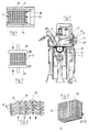
- the structure of the catalyst body can be seen more clearly from FIGS. 2 and 3. As shown, it is formed from several layers 11 from a tangle of crossing wires or fibers 12 and 13. Each Layer 11 consists of a large number of longitudinal wires or fibers 12 which are connected to wires or fibers 13 running transversely thereto. To increase the surface and the stability, the wires 11, 13 can also run in a wave shape.
- a grid-like or honeycomb-like structure with a plurality of meshes 14 is formed by this configuration, through which the exhaust gas flows.
- the individual layers can also be doped with particles in the form of small chips, small fibers or coarse powders 15 (partially shown in FIG. 2).
- This doping can e.g. by shaking, by means of a liquid in the form of a carrier substance in which the particles are contained, or the like, after which the connection is made by a sintering process or by resistance welding to the wires, fibers 12, 13.
- the catalyst body according to the invention can be carried out in a known manner by a sintering process of the wires and layers placed one above the other, which are correspondingly pressed and connected to one another in a known manner in a sintering process.
- FIG. 4 An embodiment is produced in FIG. 4 in which the individual layers are placed one on top of the other and mechanically pressed together by a clamping device with an upper plate 16 and a lower plate 17 and thus held.
- the catalyst body 7 is inserted as a unit into the exhaust manifold 5 and is fixed in position by one or more stops 18 on the rear side. On the front side, it is fixed by connecting the exhaust manifold 5 to the cylinders.
- the individual layers 11 of the catalyst body can also be connected to one another by a resistance welding between two electrodes 19 and 20 to form a solid unit.
- the resistance welding process is generally known, which is why it will not be discussed in more detail here either.
- the aforementioned materials can be used individually or in mixtures.
- carbon fibers and / or carbon particles can also be added or used alone.
- the doping particles can also be used as deposits of catalytic materials, such as the light metal oxides.
- carbon fibers and / or carbon particles either alone or in a mixture with other particles for doping the catalyst brings about a further increase in heat resistance, which is decisive in the selected range.
- the carbon fibers and / or carbon particles can be the only doping material or can be applied as a mixture with the materials mentioned above.
- Ceramic fibers for example aluminum oxide fibers, can be inserted into the catalyst body in a very advantageous manner. Such fibers reduce the heat dissipation and thus bring the temperature of the catalytic converter to the required reaction temperature even faster during cold start operation of the engine. In addition, these fibers have the advantage that they also improve the mechanical stress.
- one or more heating rods 21 or heating grids can be inserted into the catalyst body (see basic illustration in FIG. 1).
Landscapes
- Chemical & Material Sciences (AREA)
- Engineering & Computer Science (AREA)
- Chemical Kinetics & Catalysis (AREA)
- Combustion & Propulsion (AREA)
- Mechanical Engineering (AREA)
- General Engineering & Computer Science (AREA)
- Health & Medical Sciences (AREA)
- Toxicology (AREA)
- Biomedical Technology (AREA)
- Organic Chemistry (AREA)
- Materials Engineering (AREA)
- Environmental & Geological Engineering (AREA)
- Analytical Chemistry (AREA)
- General Chemical & Material Sciences (AREA)
- Oil, Petroleum & Natural Gas (AREA)
- Ceramic Engineering (AREA)
- Exhaust Gas After Treatment (AREA)
- Catalysts (AREA)
- Exhaust Silencers (AREA)
- Knitting Of Fabric (AREA)
- Combustion Methods Of Internal-Combustion Engines (AREA)
Abstract
Eine Anordnung eines Katalysators für die Abgase eines Verbrennungsmotors, wobei der Katalysatorkörper (6,7) aus einem Gewebe, Gestrick oder Gewirr aus Metallfasern, Metallspänen, Metalldrähten, Metallpulver oder einer Mischung daraus gebildet ist, die in mehreren Lagen (11) zu einem Paket zusammengepreßt sind, im Auslaßbereich (4) des Zylinders des Verbrennungsmotores vor dem Abgaskrümmer (5) und/oder im Eingangsbereich des Abgaskrümmers (5). Zusätzlich oder alternativ kann auch im Zylinder (2) des Verbrennungsmotores der Kolbenboden (8) mit einem Katalysatorkörper (9) versehen sein.
Description
Die Erfindung betrifft eine Anordnung eines Katalysators für die Abgase eines Verbrennungsmotors.The invention relates to an arrangement of a catalyst for the exhaust gases of an internal combustion engine.
Aus der DE-OS 37 43 503 ist es bereits bekannt, einen Katalysatorkörper aus einem Gewebe, Gestrick, Gewirr aus Metallfasern, Metallspänen, Metalldrähten oder Metallpulver oder einer Mischung daraus vorzusehen, der in der Abgasleitung bzw. im Auspuffsystem eines Verbrennungsmotores angeordnet ist. Der aus mehreren Lagen bestehende Katalysatorkörper ist dabei durch einen Sintervorgang gebildet.From DE-OS 37 43 503 it is already known to provide a catalyst body made of a fabric, knitted fabric, tangle of metal fibers, metal chips, metal wires or metal powder or a mixture thereof, which is arranged in the exhaust pipe or in the exhaust system of an internal combustion engine. The catalyst body consisting of several layers is formed by a sintering process.
Aus der DE-OS 39 25 596 ist es bekannt, mehrere Lagen aus Metallfasern oder Metalldrähten durch eine Widerstandsverschweißung zu einem einheitlichen Filterkörper zu verbinden.From DE-OS 39 25 596 it is known to have several layers made of metal fibers or metal wires by resistance welding to form a uniform filter body.
Neben Metall als Werkstoff sind auch Katalysatorkörper aus Keramik bekannt. Alle bekannten Katalysatoren haben jedoch den Nachteil, daß sie zu motorfern angeordnet sind. Dies bedeutet, daß sich der Abgasstrom bereits um ca. 150 bis 200 °C abgekühlt hat und dadurch den Konvertierungsgrad zur chemischen Umwandlung der Abgase verringert.In addition to metal as a material, ceramic catalyst bodies are also known. However, all known catalysts have the disadvantage that they are arranged away from the engine. This means that the exhaust gas flow has already cooled down by approx. 150 to 200 ° C., thereby reducing the degree of conversion for chemical conversion of the exhaust gases.
Nachteilig ist weiterhin auch, daß bekannte Katalysatoren Gaskanäle mit einer relativ glatten Oberfläche besitzen, so daß das Gas lediglich laminar durch die Kanäle strömt. Durch eine laminare Strömung wird jedoch nur ein geringer Teil der Abgase mit der katalytischen Beschichtung des Katalysatorkörpers in Verbindung gebracht, was den Konvertierungsgrad ebenfalls weiter negativ beeinflußt.Another disadvantage is that known catalysts have gas channels with a relatively smooth surface, so that the gas flows through the channels in a laminar manner. However, only a small part of the exhaust gases is brought into connection with the catalytic coating of the catalyst body by a laminar flow, which also has a further negative effect on the degree of conversion.
Der vorliegenden Erfindung liegt daher die Aufgabe zugrunde die vorstehend genannten Nachteile zu beseitigen, insbesondere eine Abgasreinigung mit einem Katalysator zu schaffen, der einen besseren Wirkungsgrad besitzt.The present invention is therefore based on the object of eliminating the disadvantages mentioned above, in particular to provide exhaust gas purification with a catalyst which has a better efficiency.
Erfindungsgemäß wird dies durch eine Anordnung eines Katalysators geschaffen, wobei der Katalysatorkörper aus einem Gewebe, Gestrick oder Gewirr aus Metallfasern, Metallspänen, Metalldrähten, Metallpulver oder einer Mischung daraus gebildet ist, die in ein oder mehreren Lagen zu einem Paket zusammengepreßt sind, im Auslaßbereich des Zylinders des Verbrennungsmotores vor dem Abgaskrümmer und/oder im Eingangsbereich des Abgaskrümmers.According to the invention this is created by an arrangement of a catalyst, the catalyst body being formed from a woven fabric, knitted fabric or tangle of metal fibers, metal chips, metal wires, metal powder or a mixture thereof, which are pressed together in one or more layers to form a package, in the outlet region of the Cylinder of the internal combustion engine in front of the exhaust manifold and / or in the entrance area of the exhaust manifold.
Durch die Integrierung eines Katalysators bereits in den Zylinderraum und/oder in den Eingangsbereich des sich an den Zylinder anschließenden Abgaskrümmers wird das Abgas mit deutlich höheren Temperaturen durch den Katalysatorkörper geleitet. Dies bedeutet, daß der Wirkungsgrad verbessert wird.By integrating a catalytic converter into the cylinder space and / or into the entrance area of the exhaust manifold adjoining the cylinder, the exhaust gas is conducted through the catalytic converter body at significantly higher temperatures. This means that the efficiency is improved.
Diese erfindungsgemäße Anordnung ist aufgrund der Materialwahl und der Ausbildung des Katalysatorkörpers in überraschender Weise möglich geworden. So läßt sich z.B. das erfindungsgemäße Gewebe, Gestrick oder Gewirr auf einfache Weise in die verschiedensten Formen bringen. Dies bedeutet, der Katalysatorkörper läßt sich ohne Probleme an die örtlichen Gegebenheiten, insbesondere an Form und Größe des vorhandenen Raumes in den Zylinder oder des Abgaskrümmers einpassen. Ein weiterer Vorteil besteht darin, daß ein Katalysatorkörper aus dem genannten Material und dem angegebenen Aufbau sehr kompakt herstellbar ist. Dies gilt insbesondere bei einer Ausbildung aus einem Sintermaterial, wobei der Körper zuerst in der gewünschten Form formgepreßt und anschließend gesintert wird.This arrangement according to the invention has surprisingly become possible due to the choice of material and the design of the catalyst body. For example, the fabric, knitted fabric or tangle according to the invention can easily be brought into a wide variety of shapes. This means that the catalyst body can easily be adapted to the local conditions, in particular the shape and size of the space available fit the cylinder or exhaust manifold. Another advantage is that a catalyst body can be produced very compactly from the material mentioned and the structure specified. This applies in particular to a formation from a sintered material, the body first being pressed into the desired shape and then being sintered.
Eine weitere vorteilhafte und nicht naheliegende Anordnung eines Katalysatorkörpers kann darin bestehen, daß dieser im Zylinder des Verbrennungsmotores auf den Kolbenboden aufgebracht wird. Diese Anordnung kann sowohl separat als auch in Verbindung mit einem im Auslaßbereich des Zylinders und/oder im Eingangsbereich des Abgaskrümmers angeordneten Katalysatorkörpers kombiniert werden.Another advantageous and not obvious arrangement of a catalyst body can consist in that it is applied to the piston crown in the cylinder of the internal combustion engine. This arrangement can be combined both separately and in conjunction with a catalytic converter body arranged in the outlet region of the cylinder and / or in the inlet region of the exhaust manifold.
Der fest auf dem Kolbenboden angeordnete Katalysatorkörper wird zusammen mit dem Kolben einer hin und hergehenden Bewegung unterworfen. Aufgrund der dabei auftretenden Kompressionen und Dekompressionen des Abgases wird dieses in den Katalysatorkörper bei der Kolbenbewegung hineingepreßt und wieder daraus entfernt. Dies bedeutet, daß bereits vor dem Ausstoßen des Abgases in den Auslaßkrümmer eine Abgasreinigung stattfindet.The catalyst body, which is arranged firmly on the piston crown, is subjected to a reciprocating movement together with the piston. Due to the compression and decompression of the exhaust gas that occurs, it is pressed into the catalyst body during the piston movement and removed therefrom. This means that an exhaust gas cleaning takes place before the exhaust gas is expelled into the exhaust manifold.
Da in diesem Bereich sehr hohe Temperaturen vorherrschen, die auch bereits kurz nach dem Start eines Verbrennungsmotores auftreten, besitzt der erfindungsgemäße Katalysator auch im Anfahrbereich einen sehr guten Wirkungsgrad. Dies gilt selbstverständlich auch für eine Anordnung des Katalysators im Auslaßbereich des Zylinders oder im Eingangsbereich des Abgaskrümmers in gleicher Weise.Since very high temperatures prevail in this area, which also occur shortly after the start of an internal combustion engine, the catalyst according to the invention also has a very good efficiency in the starting area. Of course, this also applies to an arrangement of the catalytic converter in the outlet area of the cylinder or in the inlet area of the exhaust manifold in the same way.
Aufgrund der Kompaktheit des Katalysatorkörpers kann zur Erhöhung des Wirkungsgrades auch noch ohne großen zusätzlichen Aufwand eine Heizeinrichtung vorgesehen werden, die den Katalysator bei Bedarf, insbesondere bei Kaltstart, kurzfristig aufheizen kann.Due to the compactness of the catalytic converter body, a heating device can be provided to increase the efficiency even without great additional effort, which can briefly heat up the catalytic converter if required, in particular during a cold start.
Eine weitere sehr vorteilhafte und nicht naheliegende Weiterbildung und Ausgestaltung der erfindungsgemäßen Katalysatoranordnung besteht darin, daß jede Lage einen Gitterstrukturaufbau aufweist.Another very advantageous and not obvious further development and configuration of the catalyst arrangement according to the invention consists in the fact that each layer has a lattice structure.
Durch den gitterartigen Aufbau werden in den Zwischenräumen bzw. Maschen durchgängige Kanäle gebildet, durch die das Abgas hindurchströmt. Durch die Maschen bzw. die Maschengitter erfolgt eine starke Verwirbelung des Abgases, so daß es zu einer erheblich besseren Kontaktierung mit der katalytisch beschichteten Oberfläche kommt, wodurch der Konvertierungsgrad verbessert wird.Through the grid-like structure, continuous channels are formed in the spaces or meshes, through which the exhaust gas flows. Due to the mesh or the mesh, there is a strong swirling of the exhaust gas, so that it is a much better Contact is made with the catalytically coated surface, which improves the degree of conversion.
Die Verwirbelung und damit Kontaktierung wird noch besser, wenn man die Maschen von hintereinander angeordneten Lagen versetzt zueinander ordnet. Dabei genügt gegebenenfalls bereits eine geringfügige Versetzung, und zwar dergestalt, daß das Abgas abwechselnd auf einen Gitterdraht auftrifft oder diesen streift, wodurch es zu einer Ablenkung und damit zu einer zusätzlichen Verwirbelung kommt.The intermingling and thus contacting becomes even better if the stitches of layers arranged one behind the other are arranged offset to one another. In this case, a slight dislocation may be sufficient, in such a way that the exhaust gas alternately strikes or brushes against a grid wire, which leads to a deflection and thus to additional swirling.
Während man bei einer Anordnung des Katalysators auf dem Kolbenboden nur eine oder gegebenenfalls wenige Lagen aus einem Gewebe, Gestrick oder Gewirr vorsieht, wird man bei einer Anordnung des Katalysatorkörpers in dem Zylinder in dessen Auslaßbereich oder im Eingangsbereich des Abgaskrümmers mehrere Lagen hintereinander anordnen. Zur einfachen Handhabung und zur besseren Wirkung wird man diese Lagen zu einer Einheit fest miteinander verbinden.While only one or possibly a few layers of a woven, knitted or tangled fabric are provided in an arrangement of the catalyst on the piston crown, an arrangement of the catalyst body in the cylinder will arrange several layers in a row in its outlet area or in the inlet area of the exhaust manifold. For easy handling and a better effect, these layers will be firmly connected to one another.
Eine mögliche Ausgestaltung hierfür kann darin bestehen, daß die Lagen durch eine Klammereinrichtung zusammengepreßt sind und als Einheit in den Auslaßbereich des Zylinders und/oder den Eingangsbereich des Abgaskrümmers eingeschoben werden.A possible embodiment for this can consist in that the layers are pressed together by a clamping device and as a unit in the outlet area of the cylinder and / or the inlet area of the exhaust manifold.
Als Klammereinrichtung sind die verschiedensten Einrichtungen denkbar. So kann z.B. ein Paket von mehreren Lagen nach Art einer Zarge durch eine Ober- und eine Unterplatte miteinander unter Druck verbunden werden.A wide variety of devices are conceivable as a clamp device. For example, a package of several layers in the manner of a frame can be connected to one another under pressure by means of an upper and a lower plate.
Eine weitere Möglichkeit der Bildung eines einheitlichen Katalysatorkörpers kann darin bestehen, daß die einzelnen Lagen durch eine widerstandsschweißung miteinander verbunden werden und als Einheit in den Auslaßbereich des Zylinders und/oder den Eingangsbereich des Abgaskrümmers eingeschoben werden.A further possibility for the formation of a uniform catalytic converter body can consist in that the individual layers are connected to one another by resistance welding and are inserted as a unit in the outlet area of the cylinder and / or the inlet area of the exhaust manifold.
Eine sehr vorteilhafte Ausgestaltung kann darin bestehen, daß die einzelnen Lagen paketiert einem Sintervorgang unterworfen werden und anschließend als Einheit in den Auslaßbereich des Zylinders und/oder den Eingangsbereich des Abgaskrümmers eingeschoben werden.A very advantageous embodiment can consist of the individual layers being subjected to a sintering process in packets and then being inserted as a unit into the outlet region of the cylinder and / or the inlet region of the exhaust manifold.
Eine weitere Verbesserung des Konvertierungsgrades durch eine Oberflächenvergrößerung und/oder eine zusätzliche Einbringung von katalytisch wirkendem Material kann dadurch erreicht werden, daß die Lagen mit Spänen, kleinen Drahtstücken, Fasern, Pulver oder dergleichen dotiert sind, die mit den Fasern, Spänen oder Drähten des Gewebes, Gestrickes oder Gewirres verbunden sind.A further improvement in the degree of conversion by increasing the surface area and / or additionally introducing catalytically active material can be achieved by using the layers Chips, small pieces of wire, fibers, powder or the like are doped, which are connected to the fibers, chips or wires of the fabric, knitted fabric or knitted fabric.
Besonders vorteilhaft läßt sich hierfür spratziges Pulver verwenden, das eine deutliche Oberflächenvergrößerung ergibt.Spicy powder can be used particularly advantageously for this purpose, which results in a significant increase in surface area.
Alternativ hierzu oder kombiniert mit einer Dotierung des Gewebes, Gestrickes oder Gewirres mit Zusatzmaterialien kann der Katalysatorkörper auch abschließend in ein Tauchbad eingebracht werden. Das Tauchbad besteht aus einem Brei bzw. einer Suspension aus Teilchen aus Metall, Keramik, Kunststoff oder ähnlichem. Nach dem Abtropfen wird die zusätzliche Schicht gehärtet oder einem Sinterprozeß unterworfen. Ein ähnliches Verfahren ist auch als "Wash-Coat-Verfahren" bekannt.As an alternative to this, or in combination with a doping of the fabric, knitted fabric or knitted fabric with additional materials, the catalyst body can also be finally introduced into an immersion bath. The immersion bath consists of a slurry or a suspension of particles made of metal, ceramic, plastic or the like. After draining, the additional layer is hardened or subjected to a sintering process. A similar process is also known as the "wash coat process".
Zur Lagefixierung des als Einheit in einen Abgaskrümmer einschiebbaren Katalysatorkörpers kann der Abgaskrümmer auch mit ein oder mehreren Anschlägen versehen sein.The exhaust manifold can also be provided with one or more stops in order to fix the position of the catalyst body which can be inserted as a unit into an exhaust manifold.
Nachfolgend sind anhand der Zeichnung Ausführungsbeispiele der Erfindung prinzipmäßig dargestellt.Exemplary embodiments of the invention are shown in principle below with reference to the drawing.
Es zeigt:
- Fig. 1
- einen Schnitt durch den oberen Teil eines Verbrennungsmotores mit mehreren erfindungsgemäßen Anordnungen eines Katalysatorkörpers;
- Fig. 2
- ausschnittsweise eine vergrößerte Darstellung des erfindungsgemäßen Katalysatorkörpers;
- Fig. 3
- eine perspektivische Darstellung einer aus mehreren Lagen gebildeten Einheit eines Katalysatorkörpers;
- Fig. 4
- einen Schnitt durch einen Katalysatorkörper, der durch eine Klammereinrichtung zusammengehalten ist;
- Fig. 5
- einen Schnitt durch einen Katalysatorkörper, der durch eine Widerstandsverschweißung gebildet ist.
- Fig. 1
- a section through the upper part of an internal combustion engine with several arrangements of a catalyst body according to the invention;
- Fig. 2
- excerpts an enlarged view of the catalyst body according to the invention;
- Fig. 3
- a perspective view of a unit formed from several layers of a catalyst body;
- Fig. 4
- a section through a catalyst body, which is held together by a clamp device;
- Fig. 5
- a section through a catalyst body, which is formed by a resistance welding.
In der Fig. 1 ist prinzipmäßig der obere Bereich eines Verbrennungsmotores mit einem Kolben 1, der in bekannter Weise in einen Zylinder 2 Hub- und Senkbewegungen ausführt, dargestellt. Der Aufbau eines Verbrennungsmotores ist allgemein bekannt, weshalb hier nicht näher darauf eingegangen wird. Ein Auslaßventil 3 schließt einen Auslaßbereich 4 im Zylinder 2 ab bzw. gibt diesen entsprechend gesteuert zum Ausstoßen von Abgas frei. An den Auslaßbereich 4 schließt sich ein Abgaskrümmer 5 an.1 shows in principle the upper area of an internal combustion engine with a
Wie ersichtlich ist ein Katalysatorkörper 6 im Auslaßbereich 4 und ein weiterer Katalysatorkörper 7 im Eingangsbereich des Auslaßkrümmers 5 angeordnet. Auf den gekrümmten Kolbenboden 8 des Kolbens 1 ist ein entsprechend gekrümmter Katalysatorkörper 9 aufgebracht.As can be seen, a
Zur Vereinfachung sind in die Fig. 1 drei Möglichkeiten der Anordnung eines Katalysatorkörpers aufgezeigt. Neben dieser Darstellungsform sind selbstverständlich auch noch andere Kombinationsmöglichkeiten gegeben. So kann z.B. der Katalysatorkörper 6 oder 7 alleine in Verbindung mit dem Katalysatorkörper 9 vorgesehen sein. Ebenso können die Katalysatorkörper 6 und 7 auch gemeinsam oder alleine vorgesehen sein.For simplification, three options for the arrangement of a catalyst body are shown in FIG. 1. In addition to this form of presentation, there are of course other possible combinations. For example, the
Der Aufbau des Katalysatorkörpers ist aus den Fig. 2 und 3 deutlicher ersichtlich. Wie dargestellt ist er aus mehreren Lagen 11 aus einem Gewirr von sich kreuzenden Drähten oder Fasern 12 und 13 gebildet. Jede Lage 11 besteht dabei aus einer Vielzahl von Längsdrähten oder Fasern 12, die mit quer dazu verlaufenden Drähten oder Fasern 13 verbunden sind. Zur Erhöhung der Oberfläche und der Stabilität können die Drähte 11, 13 auch wellenförmig verlaufen.The structure of the catalyst body can be seen more clearly from FIGS. 2 and 3. As shown, it is formed from
Aus der Fig. 3 ist ersichtlich, daß durch diese Ausgestaltung eine gitterartige bzw. wabenartige Struktur mit einer Vielzahl von Maschen 14 gebildet wird, durch die das Abgas strömt.From Fig. 3 it can be seen that a grid-like or honeycomb-like structure with a plurality of
Bei der Strömung des Abgases gemäß Pfeilrichtung der Fig. 2 erfolgt eine entsprechende Verwirbelung durch die Drähte bzw. Fasern 12 und 13. Diese Verwirbelung und damit bessere Kontaktierung mit den katalytisch beschichteten Drähten oder Fasern 12, 13 wird noch erhöht, wenn hintereinanderliegende Drähte 12 versetzt zueinander angeordnet sind (siehe gestrichelte Darstellung).When the exhaust gas flows in the direction of the arrow in FIG. 2, there is a corresponding swirling through the wires or
Zur Oberflächenvergrößerung und zur Erhöhung der katalytischen Wirksamkeit können die einzelnen Lagen auch noch mit Partikel in Form von kleinen Spänen, kleinen Fasern oder groben Pulvern 15 dotiert werden (teilweise in der Fig. 2 dargestellt).To increase the surface area and to increase the catalytic effectiveness, the individual layers can also be doped with particles in the form of small chips, small fibers or coarse powders 15 (partially shown in FIG. 2).
Diese Dotierung kann z.B. durch ein Einrütteln, durch ein Mittel in flüssiger Form als Trägersubstanz, in der die Partikel aufgenommen sind, oder dergleichen erfolgen, wonach die Verbindung durch einen Sintervorgang oder durch eine Widerstandsverschweißung mit den Drähten, Fasern 12, 13 erfolgt.This doping can e.g. by shaking, by means of a liquid in the form of a carrier substance in which the particles are contained, or the like, after which the connection is made by a sintering process or by resistance welding to the wires,
Der erfindungsgemäße Katalysatorkörper kann in bekannter Weise durch einen Sintervorgang der übereinander gelegten Drähten und Lagen erfolgen, die entsprechend gepreßt und in bekannter Weise in einem Sintervorgang miteinander verbunden werden.The catalyst body according to the invention can be carried out in a known manner by a sintering process of the wires and layers placed one above the other, which are correspondingly pressed and connected to one another in a known manner in a sintering process.
In Fig. 4 ist eine Ausführungsform hergestellt, in der die einzelnen Lagen übereinander gelegt werden und durch eine Klammereinrichtung mit einer Oberplatte 16 und einer Unterplatte 17 mechanisch zusammengepreßt und so gehalten werden.An embodiment is produced in FIG. 4 in which the individual layers are placed one on top of the other and mechanically pressed together by a clamping device with an
Aus der Fig. 4 ist auch ersichtlich, wie der Katalysatorkörper 7 als Einheit in den Abgaskrümmer 5 eingeschoben wird und in diesem durch ein oder mehrere Anschläge 18 auf der hinteren Seite in seiner Lage fixiert ist. Auf der vorderen Seite erfolgt die Fixierung durch den Anschluß des Abgaskrümmers 5 an den Zylindern.4 also shows how the
Statt einer einfachen mechanischen Zusammenpreßung der einzelnen Lagen 11 des Katalysatorkörpers können die einzelnen Lagen auch durch eine Widerstandsverschweißung zwischen zwei Elektroden 19 und 20 zu einer massiven Einheit miteinander verbunden werden. Das Widerstandsverschweißungsverfahren ist allgemein bekannt, weshalb hier nachfolgend ebenfalls nicht näher darauf eingegangen wird.Instead of a simple mechanical compression of the
Als Material zur Bildung des Katalysatorkörpers aus den Metallfasern, Metallspänen, Metalldrähten, Metallpulver oder einer Mischung daraus sind z.B. folgende Materialien geeignet:
- 1. Werkstoffe einer intermetalllschen (intensive Mischung) Phase, wie Ni₃Al, NiAl, Ti₃Al, TiAl, Mg₂Si, Al₃Mg, MnZr₂, Ti₅Si₃.
- 2. Stähle mit einem 17-26% Cr, Ni 3-37%, Si 0,7-2,5%; c < 0,1 %; Mn 1-2 %, P ≦ 0,03 %; S ≦ 0,02 %, Al 0,7-6 % Gehalt.
- 3. Stähle:
- a) 18,5 % Cr; 9,5 % Ni,
N 0,15 %,Si - b) 21 % Cr, 11 % Ni, 1,7 % Si, C < 0,1 %,
N 0,17 % und seltene Erdmetalle, vorwiegend Cerium. - c) 25 % Cr; 35 % Ni, 1,5 % Si, C < 0,05 % und seltene Erdmetalle, vorwiegend Cerium.
- a) 18,5 % Cr; 9,5 % Ni,
- 1. Materials of an intermetallic (intensive mixture) phase, such as Ni₃Al, NiAl, Ti₃Al, TiAl, Mg₂Si, Al₃Mg, MnZr₂, Ti₅Si₃.
- 2. steels with a 17-26% Cr, Ni 3-37%, Si 0.7-2.5%; c <0.1%; Mn 1-2%, P ≦ 0.03%; S ≦ 0.02%, Al 0.7-6% content.
- 3. Steels:
- a) 18.5% Cr; 9.5% Ni, N 0.15%, Si 1.3%, C <0.06%, and a small amount of rare earth metals, predominantly cerium.
- b) 21% Cr, 11% Ni, 1.7% Si, C <0.1%, N 0.17% and rare earth metals, mainly cerium.
- c) 25% Cr; 35% Ni, 1.5% Si, C <0.05% and rare earth metals, mainly cerium.
Als Dotierungspartikel für die einzelnen Lagen 11 können folgende Materialien verwendet werden:
- 1. Materialien analog dem Grundmaterial.
- 2. Leichtmetalloxyde wie AlxOy, SixOy: z.B Al₂O₃, SiO₂, oder SiTiO₃, AlTiO₅, SiO₂, ZrO₂, SiC, TiO₂, BaTiO₃, Si₃N₄, Cr₂O₃.
- 1. Materials analogous to the basic material.
- 2. Light metal oxides such as Al x O y , Si x O y : for example Al₂O₃, SiO₂, or SiTiO₃, AlTiO₅, SiO₂, ZrO₂, SiC, TiO₂, BaTiO₃, Si₃N₄, Cr₂O₃.
Die vorgenannten Materialen können einzeln oder in Mischungen verwendet werden. Zusätzlich können noch Kohlenstoffasern und/oder Kohlenstoffpartikel beigemischt oder auch alleine verwendet werden.The aforementioned materials can be used individually or in mixtures. In addition, carbon fibers and / or carbon particles can also be added or used alone.
Die Verwendung von Aluminium hat den Vorteil, daß sich dieses an der Oberfläche abscheidet und dort eine sehr korrosionsfeste Schicht bildet. Weiterhin hat sich herausgestellt, daß es ein gutes "Verankerungsmittel" für eine zusätzliche Schicht bilden kann, wie z.B. bei einer zusätzlichen Aufbringung von Teilchen in einem Tauchbad.The use of aluminum has the advantage that it deposits on the surface and forms a very corrosion-resistant layer there. It has also been found that it can form a good "anchoring agent" for an additional layer, such as in an additional application of particles in an immersion bath.
Weiterhin können die Dotierungspartikel auch als Einlagen von katalytischen Materialien, wie z.B. die Leichtmetalloxyde, dienen.Furthermore, the doping particles can also be used as deposits of catalytic materials, such as the light metal oxides.
Eine Zugabe von Kohlenstoffasern und/oder Kohlenstoffpartikeln entweder allein oder in Mischung mit anderen Partikeln zur Dotierung des Katalysators bringt eine weitere Erhöhung der Hitzebeständigkeit, die ja gerade in dem gewählten Bereich entscheidend ist. Die Kohlenstoffasern und/oder Kohlenstoffpartikeln können dabei das einzige Dotierungsmaterial darstellen oder mit den vorstehend genannten Materialien als Mischung aufgebracht werden.The addition of carbon fibers and / or carbon particles either alone or in a mixture with other particles for doping the catalyst brings about a further increase in heat resistance, which is decisive in the selected range. The carbon fibers and / or carbon particles can be the only doping material or can be applied as a mixture with the materials mentioned above.
In einer sehr vorteilhaften Weise lassen sich keramische Fasern, z.B. Aluminiumoxydfasern, in den Katalysatorkörper einfügen. Derartige Fasern vermindern die Wärmeabfuhr und bringen damit eine noch schnellere Temperaturerhöhung des Katalysators im Kaltstartbetrieb des Motores auf die erforderliche Reaktionstemperatur. Darüberhinaus haben diese Fasern den Vorteil, daß sie auch die mechanische Beanspruchung verbessern.Ceramic fibers, for example aluminum oxide fibers, can be inserted into the catalyst body in a very advantageous manner. Such fibers reduce the heat dissipation and thus bring the temperature of the catalytic converter to the required reaction temperature even faster during cold start operation of the engine. In addition, these fibers have the advantage that they also improve the mechanical stress.
Zur Erhöhung der Wirksamkeit des Katalysatorkörpers 6 oder 7 können ein oder mehrere Heizstäbe 21 oder Heizgitter in den Katalysatorkörper eingeschoben werden (siehe Prinzipdarstellung in der Fig. 1).In order to increase the effectiveness of the
Claims (23)
dadurch gekennzeichnet, daß jede Lage (11) einen Gitterstrukturaufbau aufweist.Arrangement according to claim 1 or 2,
characterized in that each layer (11) has a lattice structure.
dadurch gekennzeichnet, daß die Gittermaschen (14) von hintereinander angeordneten Lagen (11) versetzt zueinander angeordnet sind.Arrangement according to claim 3,
characterized in that the grid meshes (14) of layers (11) arranged one behind the other are arranged offset to one another.
dadurch gekennzeichnet, daß die Maschenweite 0,5 bis 5 mm, vorzugsweise 1 bis 2 mm beträgt.Arrangement according to claim 3 or 4,
characterized in that the mesh size is 0.5 to 5 mm, preferably 1 to 2 mm.
dadurch gekennzeichnet, daß die Drähte oder Fasern (12,13) einer Lage (11) wenigstens annähernd eine Wellenform aufweisen.Arrangement according to one of claims 1 to 5,
characterized in that the wires or fibers (12, 13) of a layer (11) have at least approximately a wave shape.
dadurch gekennzeichnet, daß die Lagen (11) durch eine Klammereinrichtung (16, 17) zusammengepreßt sind und als Einheit in den Auslaßbereich des Zylinders (2) und/oder den Eingangsbereich des Abgaskrümmers (5) eingeschoben werden.Arrangement according to one of claims 1 to 6,
characterized in that the layers (11) are pressed together by a clamping device (16, 17) and are inserted as a unit into the outlet area of the cylinder (2) and / or the input area of the exhaust manifold (5).
dadurch gekennzeichnet, daß die einzelnen Lagen (11) durch eine Widerstandsverschweißung miteinander verbunden sind und als Einheit in den Auslaßbereich des Zylinders (2) und/oder den Eingangsbereich des Abgaskrümmers (5) eingeschoben werden.Arrangement according to one of claims 1 to 6,
characterized in that the individual layers (11) are connected to one another by resistance welding and are inserted as a unit in the outlet region of the cylinder (2) and / or the inlet region of the exhaust manifold (5).
dadurch gekennzeichnet, daß die einzelnen Lagen (11) paketiert einem Sintervorgang unterworfen werden und anschließend als Einheit in den Auslaßbereich des Zylinders (2) und/oder den Eingangsbereich des Abgaskrümmers (5) eingeschoben werden.Arrangement according to one of claims 1 to 6,
characterized in that the individual layers (11) are subjected to a sintering process in packets and are then inserted as a unit into the outlet region of the cylinder (2) and / or the inlet region of the exhaust manifold (5).
dadurch gekennzeichnet, daß die Lagen (11) mit Spänen, kleinen Drahtstücken, Fasern (15) oder dergleichen dotiert sind, die mit den Fasern, Spänen oder Drähten (12,13) des Gewebes, Gestrickes oder Gewirres verbunden sind.Arrangement according to one of claims 1 to 9,
characterized in that the layers (11) are doped with chips, small pieces of wire, fibers (15) or the like, which with the fibers, chips or wires (12, 13) of the fabric, knitted fabric or knitted fabric are connected.
dadurch gekennzeichnet, daß spratziges Pulver (15), das katalytische Eigenschaften besitzt, vorgesehen ist.Arrangement according to claim 10,
characterized in that spicy powder (15) having catalytic properties is provided.
dadurch gekennzeichnet, daß die Verbindung der Späne, kurzer Drahtstücke, Fasern oder des Pulvers (15) mit den Fasern, Spänen oder Drähten (12,13) des Gewebes, des Gestrickes oder Gewirres durch Widerstandsverschweißung oder Versinterung erfolgt.Arrangement according to claim 10 or 11,
characterized in that the shavings, short pieces of wire, fibers or the powder (15) are connected to the fibers, shavings or wires (12, 13) of the woven fabric, the knitted fabric or the knitted fabric by resistance welding or sintering.
dadurch gekennzeichnet, daß der Katalysatorkörper (6,7,9) in einem Tauchbad mit die Oberfläche des Katalysatorkörpers (6,7,9) vergrößernden Teilchen versehen wird.Arrangement according to one of claims 1 to 12,
characterized in that the catalyst body (6, 7, 9) is provided with particles enlarging the surface of the catalyst body (6, 7, 9) in an immersion bath.
dadurch gekennzeichnet, daß das Material für den Katalysatorkörper Werkstoffe einer intermetallischen (intensive Mischung) Phase wie Ni₃Al, NiAl, Ti₃Al, TiAl, Mg₂Si, Al₃Mg, MnZr₂, Ti₅Si₃ aufweist.Arrangement according to one of claims 1 to 13,
characterized in that the material for the catalyst body materials of an intermetallic (intensive mixture) phase such as Ni₃Al, NiAl, Ti₃Al, TiAl, Mg₂Si, Al₃Mg, MnZr₂, Ti₅Si₃.
dadurch gekennzeichnet, daß das Material für den Katalysatorkörper Stähle mit 17-26 % Cr, Ni 3-37 %, Si 0,7-2,5 %; C < 0,1 %; Mn 1-2 %, P ≦ 0,03 %; S ≦ 0,02 %, Al 0,7-6 % Gehalt aufweist.Arrangement according to one of claims 1 to 13,
characterized in that the material for the catalyst body steels with 17-26% Cr, Ni 3-37%, Si 0.7-2.5%; C <0.1%; Mn 1-2%, P ≦ 0.03%; S ≦ 0.02%, Al 0.7-6% content.
dadurch gekennzeichnet, daß das Material für den Katalysatorkörper Stähle mit 18,5 % Cr, 9,5 % Ni, N 0,15 %, Si 1,3 %, C < 0,06 %, und geringe Mengen von seltenen Erdmetallen, vorwiegend Cerium aufweist.Arrangement according to one of claims 1 to 13,
characterized in that the material for the catalyst body steels with 18.5% Cr, 9.5% Ni, N 0.15%, Si 1.3%, C <0.06%, and small amounts of rare earth metals, predominantly Cerium has.
dadurch gekennzeichnet, daß das Material für den Katalysatorkörper Stähle mit 21 % Cr, 11 % Ni, 1,7 % Si, C < 0,1 %, N 0,17 % und seltene Erdmetalle, vorwiegend Cerium aufweist.Arrangement according to one of claims 1 to 13,
characterized in that the material for the catalyst body has steels with 21% Cr, 11% Ni, 1.7% Si, C <0.1%, N 0.17% and rare earth metals, mainly cerium.
dadurch gekennzeichnet, daß das Material für den Katalysatorkörper Stähle mit 25 % Cr; 35 % Ni, 1,5 % Si, C < 0,05 % und seltene Erdmetalle, vorwiegend Cerium aufweist.Arrangement according to one of claims 1 to 13,
characterized in that the material for the catalyst body steels with 25% Cr; 35% Ni, 1.5% Si, C <0.05% and rare earth metals, mainly cerium.
dadurch gekennzeichnet, daß als Dotierungspartikel Metalle, Metalloxyde, Keramik, Kunststoffe oder eine Mischung daraus vorgesehen ist.Arrangement according to one of claims 1 to 18,
characterized in that metals, metal oxides, ceramics, plastics or a mixture thereof are provided as doping particles.
dadurch gekennzeichnet, daß katalytisch wirkende Partikel, wie Cr, Va, Mo, Mn, Pt, Rh, Pd, Ti, Si jeweils einzeln oder in Mischung vorgesehen sind.Arrangement according to claim 19,
characterized in that catalytically active particles such as Cr, Va, Mo, Mn, Pt, Rh, Pd, Ti, Si are provided individually or in a mixture.
dadurch gekennzeichnet, daß Al₂O₃, SiTiO₃, AlTiO₅, SiO₂, ZrO₂, SiC, TiO₂, BaTiO₃, Si₃N₄, Cr₂O₃ jeweils einzeln oder in Mischung vorgesehen sind.Arrangement according to claim 19,
characterized in that Al₂O₃, SiTiO₃, AlTiO₅, SiO₂, ZrO₂, SiC, TiO₂, BaTiO₃, Si₃N₄, Cr₂O₃ are provided individually or in a mixture.
dadurch gekennzeichnet, daß als Dotierungspartikel Kohlenstoffasern und/oder Kohlenstoffpartikel alleine oder in Mischung zugegeben sind.Arrangement according to one of claims 1 to 21,
characterized in that carbon fibers and / or carbon particles added alone or in a mixture as doping particles are.
dadurch gekennzeichnet, daß als Dotierungspartikel keramische Fasern, insbesondere Aluminiumoxidfasern, alleine oder in Mischung zugegeben sind.Arrangement according to one of claims 1 to 21,
characterized in that ceramic fibers, in particular aluminum oxide fibers, are added alone or as a mixture as doping particles.
Priority Applications (1)
| Application Number | Priority Date | Filing Date | Title |
|---|---|---|---|
| EP95104354A EP0665367A3 (en) | 1991-11-12 | 1992-10-21 | Arrangement of the catalytic converter for the exhaust gases of an internal combustion engine |
Applications Claiming Priority (3)
| Application Number | Priority Date | Filing Date | Title |
|---|---|---|---|
| DE4137105A DE4137105A1 (en) | 1991-11-12 | 1991-11-12 | ARRANGEMENT OF A CATALYST FOR THE EXHAUST GAS FROM A COMBUSTION ENGINE |
| DE4137105 | 1991-11-12 | ||
| US07/965,800 US5425236A (en) | 1991-11-12 | 1992-10-23 | Catalyzer arrangement for the exhaust gases of an internal combustion engine |
Related Child Applications (2)
| Application Number | Title | Priority Date | Filing Date |
|---|---|---|---|
| EP95104354.6 Division-Into | 1992-10-21 | ||
| EP95104354A Division EP0665367A3 (en) | 1991-11-12 | 1992-10-21 | Arrangement of the catalytic converter for the exhaust gases of an internal combustion engine |
Publications (3)
| Publication Number | Publication Date |
|---|---|
| EP0542002A2 true EP0542002A2 (en) | 1993-05-19 |
| EP0542002A3 EP0542002A3 (en) | 1993-07-14 |
| EP0542002B1 EP0542002B1 (en) | 1996-01-03 |
Family
ID=25909012
Family Applications (2)
| Application Number | Title | Priority Date | Filing Date |
|---|---|---|---|
| EP92117984A Expired - Lifetime EP0542002B1 (en) | 1991-11-12 | 1992-10-21 | Catalytic converter for the exhaust gases of an internal combustion engine |
| EP95104354A Withdrawn EP0665367A3 (en) | 1991-11-12 | 1992-10-21 | Arrangement of the catalytic converter for the exhaust gases of an internal combustion engine |
Family Applications After (1)
| Application Number | Title | Priority Date | Filing Date |
|---|---|---|---|
| EP95104354A Withdrawn EP0665367A3 (en) | 1991-11-12 | 1992-10-21 | Arrangement of the catalytic converter for the exhaust gases of an internal combustion engine |
Country Status (7)
| Country | Link |
|---|---|
| US (1) | US5425236A (en) |
| EP (2) | EP0542002B1 (en) |
| JP (1) | JPH06129247A (en) |
| AT (1) | ATE132576T1 (en) |
| CA (1) | CA2082188A1 (en) |
| DE (2) | DE4137105A1 (en) |
| ES (1) | ES2083052T3 (en) |
Cited By (3)
| Publication number | Priority date | Publication date | Assignee | Title |
|---|---|---|---|---|
| EP0780550A1 (en) * | 1995-12-18 | 1997-06-25 | Honda Giken Kogyo Kabushiki Kaisha | Engine exhaust emission control system |
| WO1997040936A1 (en) * | 1996-04-30 | 1997-11-06 | Zentox Corporation | Fibrous matte support and method for the photopromoted catalyzed degradation of compounds in a fluid stream |
| WO1999013985A1 (en) * | 1997-09-12 | 1999-03-25 | Institut Für Umwelttechnologie Und Umweltanalytik E.V. (Iuta) - Institut An Der Gerhard-Mercator-Universität-Gesamthochschule Duisburg | Method and device for catalytic emissions cleaning |
Families Citing this family (31)
| Publication number | Priority date | Publication date | Assignee | Title |
|---|---|---|---|---|
| DE4223277C2 (en) * | 1992-07-15 | 2001-07-19 | Linde Ag | Method and device for removing particles from exhaust gases from internal combustion engines |
| US6284201B1 (en) | 1993-02-10 | 2001-09-04 | Alfred Buck | Apparatus for the catalytic purification of flowing gases, in particular exhaust gases of internal combustion engines |
| DE4303850C1 (en) * | 1993-02-10 | 1994-10-13 | Alfred Buck | Device for the catalytic cleaning of flowing gases, in particular exhaust gases from internal combustion engines |
| US6058918A (en) * | 1994-08-03 | 2000-05-09 | Financieres C. Vernes | Combustion catalyst device for an internal combustion engine |
| US6176701B1 (en) * | 1997-10-01 | 2001-01-23 | Barnett Joel Robinson | Method for improving fuel efficiency in combustion chambers |
| DE19753407C2 (en) * | 1997-12-02 | 2000-08-03 | Invent Gmbh Entwicklung Neuer Technologien | Process and apparatus for converting heat into work |
| DE19904314A1 (en) * | 1999-01-28 | 2000-08-17 | Porsche Ag | Exhaust gas purifying device has a catalyst arrangement consisting of a main catalyst and several pre-catalysts arranged relatively near to the cylinder head |
| AU3520000A (en) * | 1999-03-09 | 2000-09-28 | Abb Lummus Global Inc. | Exhaust gas catalytic converter |
| AU5616900A (en) * | 1999-06-29 | 2001-01-31 | Abb Lummus Global Inc. | Process for coating metal fibrous material |
| US6667017B2 (en) | 1999-10-15 | 2003-12-23 | Abb Lummus Global, Inc. | Process for removing environmentally harmful compounds |
| AU769548B2 (en) | 1999-10-15 | 2004-01-29 | Abb Lummus Global Inc. | Conversion of nitrogen oxides in the presence of a catalyst supported of a mesh-like structure |
| RU2175393C2 (en) * | 2000-01-05 | 2001-10-27 | Военный автомобильный институт | Internal combustion engine exhaust gas outlet device |
| DE10016841A1 (en) * | 2000-04-05 | 2001-10-18 | Drafas Gmbh | Formable mesh fabric composite |
| US7188470B2 (en) * | 2001-10-10 | 2007-03-13 | Dominique Bosteels | Combustion process |
| US6725656B2 (en) | 2001-12-07 | 2004-04-27 | Dan T. Moore Company | Insulated exhaust manifold |
| WO2003050397A2 (en) * | 2001-12-07 | 2003-06-19 | Dan T. Moore Company | Insulated exhaust manifold having internal catalyst support body |
| US20040177609A1 (en) * | 2001-12-07 | 2004-09-16 | Moore Dan T. | Insulated exhaust manifold having ceramic inner layer that is highly resistant to thermal cycling |
| ITTO20030059A1 (en) * | 2003-01-31 | 2004-08-01 | Fiat Ricerche | DIRECT INJECTION DIESEL ENGINE, WITH COMBUSTION |
| DE10337265A1 (en) | 2003-08-13 | 2005-03-10 | Emitec Emissionstechnologie | Roll seam welded body for exhaust gas treatment |
| JP3955291B2 (en) * | 2004-07-13 | 2007-08-08 | 株式会社共立 | Muffler with catalyst for internal combustion engine |
| JPWO2006080441A1 (en) * | 2005-01-28 | 2008-06-19 | 株式会社平岡製作所 | Muffler for small engines |
| DE102005023384A1 (en) * | 2005-05-17 | 2006-11-23 | Emitec Gesellschaft Für Emissionstechnologie Mbh | Welding process for forming a metal fibre mesh of a type built into an automobile catalytic exhaust gas converter |
| DE102005023385A1 (en) * | 2005-05-17 | 2006-11-23 | Emitec Gesellschaft Für Emissionstechnologie Mbh | Joining of metallic fibers to nonwovens for the production of honeycomb bodies |
| DE102006001833A1 (en) * | 2006-01-13 | 2007-07-19 | Emitec Gesellschaft Für Emissionstechnologie Mbh | Discontinuous welding of metallic fibers |
| CN101827638B (en) | 2007-08-03 | 2016-07-13 | 埃尔西韦公司 | Porous bodies and methods |
| DE102008027328A1 (en) | 2008-06-07 | 2009-12-10 | Volkswagen Ag | Internal combustion engine e.g. diesel engine, exhaust line, has deformable catalyst body arranged in-front of and/or after pre-converter and/or in inlet and/or outlet region and as insert in sound absorber |
| US8277743B1 (en) | 2009-04-08 | 2012-10-02 | Errcive, Inc. | Substrate fabrication |
| US8359829B1 (en) | 2009-06-25 | 2013-01-29 | Ramberg Charles E | Powertrain controls |
| US9833932B1 (en) | 2010-06-30 | 2017-12-05 | Charles E. Ramberg | Layered structures |
| KR102456482B1 (en) | 2018-04-04 | 2022-10-19 | 유니프랙스 아이 엘엘씨 | Activated porous fibers and products comprising the same |
| DE102018112836A1 (en) | 2018-05-29 | 2018-07-12 | FEV Europe GmbH | Cylinder head of an internal combustion engine |
Family Cites Families (67)
| Publication number | Priority date | Publication date | Assignee | Title |
|---|---|---|---|---|
| US3124930A (en) * | 1964-03-17 | Exhaust system | ||
| US1793813A (en) * | 1926-10-20 | 1931-02-24 | Mackinnon Daniel Albert | Means for neutralizing poisonous engine gases |
| BE369912A (en) * | 1929-12-04 | |||
| US2267918A (en) * | 1940-03-27 | 1941-12-30 | Gen Motors Corp | Porous article and method of making same |
| FR992440A (en) * | 1948-08-16 | 1951-10-18 | Alliance Europ | Improvements to internal combustion engines |
| US3161478A (en) * | 1959-05-29 | 1964-12-15 | Horst Corp Of America V D | Heat resistant porous structure |
| US3087233A (en) * | 1960-11-16 | 1963-04-30 | Fram Corp | Pervious metal fiber material and method of making the same |
| FR1358557A (en) * | 1963-03-05 | 1964-04-17 | Commissariat Energie Atomique | Combustion catalyst and its manufacturing process |
| US3306353A (en) * | 1964-12-23 | 1967-02-28 | Olin Mathieson | Heat exchanger with sintered metal matrix around tubes |
| FR1453653A (en) * | 1965-11-12 | 1966-06-03 | Dunlop Rubber Co | Filter for gases and liquids |
| US3819334A (en) * | 1970-10-27 | 1974-06-25 | Mitsui Mining & Smelting Co | Catalytic reaction apparatus for purifying waste gases containing carbon monoxide |
| US3648676A (en) * | 1971-03-17 | 1972-03-14 | Environmental Quality Engineer | Process for reducing detonation |
| FR2145340A5 (en) * | 1971-07-08 | 1973-02-16 | Hinderks M V | |
| US3927525A (en) * | 1973-05-25 | 1975-12-23 | Gen Motors Corp | Engine with exhaust manifold converter-reactor |
| DE2430983A1 (en) * | 1973-07-12 | 1975-01-30 | Inst Ciezkiej Syntezy Orga | COMBUSTION ENGINE THAT EMITS COMBUSTION GASES WITH LOW CONTENT OF TOXIC COMPONENTS |
| US3904551A (en) * | 1973-12-19 | 1975-09-09 | Grace W R & Co | Process for preparing an auto exhaust catalytic converter |
| US4064914A (en) * | 1974-05-08 | 1977-12-27 | Union Carbide Corporation | Porous metallic layer and formation |
| US4062807A (en) * | 1975-06-17 | 1977-12-13 | Tokyo Shibaura Electric Co., Ltd. | Nitrogen oxide reducing catalyst |
| GB1578027A (en) * | 1976-06-10 | 1980-10-29 | Ricardo Consulting Engs Ltd | Ic engines having catalytic ignition |
| US4183896A (en) * | 1976-06-16 | 1980-01-15 | Gordon Donald C | Anti-pollution device for exhaust gases |
| GB1567593A (en) * | 1976-10-20 | 1980-05-21 | Matsushita Electric Industrial Co Ltd | Exhaust gas control equipment |
| GB1560311A (en) * | 1978-02-13 | 1980-02-06 | Secr Defence | Combustion chamber components |
| JPS54128842A (en) * | 1978-03-29 | 1979-10-05 | Bridgestone Corp | Thermal collector |
| JPS54152241A (en) * | 1978-04-20 | 1979-11-30 | Mtp Kasei Kk | Solar heat collecting body |
| DE2853547C2 (en) * | 1978-12-12 | 1983-11-03 | Degussa Ag, 6000 Frankfurt | Carrier for catalysts with cross-flow effect and use, traversed by flow channels |
| US4301012A (en) * | 1979-04-25 | 1981-11-17 | Purolator Technologies, Inc. | Welded stainless steel mesh cleanable filter |
| FR2462188A1 (en) * | 1979-07-25 | 1981-02-13 | Tissmetal Lionel Dupont | Filter for gases or liq. - where substrate fabric or felt is covered by grains of thermoplastic polymer bonded to fabric by heating |
| DE2951316A1 (en) * | 1979-12-20 | 1981-07-02 | Degussa Ag, 6000 Frankfurt | CATALYTIC FILTER FOR DIESEL EXHAUST CLEANING |
| JPS577216A (en) * | 1980-06-16 | 1982-01-14 | Ngk Insulators Ltd | Ceramic honeycomb filter and preparation thereof |
| US4329162A (en) * | 1980-07-03 | 1982-05-11 | Corning Glass Works | Diesel particulate trap |
| US4359864A (en) * | 1981-02-05 | 1982-11-23 | Caterpillar Tractor Co. | Burn-out type cleaning means for particulate filter of engine exhaust system |
| US4811707A (en) * | 1981-03-30 | 1989-03-14 | Pfefferle William C | Method of operating catalytic ignition engines and apparatus therefor |
| AU540009B2 (en) * | 1982-02-16 | 1984-10-25 | Matsushita Electric Industrial Co., Ltd. | Exhaust gas filter |
| US4417908A (en) * | 1982-02-22 | 1983-11-29 | Corning Glass Works | Honeycomb filter and method of making it |
| DE3232729A1 (en) * | 1982-09-03 | 1984-03-08 | Degussa Ag, 6000 Frankfurt | METHOD FOR REDUCING THE IGNITION TEMPERATURE OF DIESEL CARBON FILTERED OUT OF THE EXHAUST GAS FROM DIESEL ENGINES |
| DE3331579A1 (en) * | 1983-09-01 | 1985-03-21 | Klöckner-Humboldt-Deutz AG, 5000 Köln | Piston internal combustion engine |
| FR2551494A1 (en) * | 1983-09-07 | 1985-03-08 | Kervagoret Alain | METHOD FOR IMPROVING THE OPERATION OF AN INTERNAL COMBUSTION ENGINE, DEVICE FOR CARRYING OUT SAID METHOD, AND INTERNAL COMBUSTION ENGINE EQUIPPED WITH SAID DEVICE |
| EP0172642B1 (en) * | 1984-07-09 | 1989-05-24 | Takeda Chemical Industries, Ltd. | Powder-air filter and separator for use in a powder filling apparatus |
| DE3509969A1 (en) * | 1985-03-20 | 1985-11-21 | Friedrich 5000 Köln Elles | Exhaust catalytic converter cartridge for afterburning and silencing on internal combustion engines |
| JPS61287451A (en) * | 1985-06-13 | 1986-12-17 | Nippon Denso Co Ltd | Catalyst carrier for exhaust gas purification |
| JPH062204B2 (en) * | 1985-06-24 | 1994-01-12 | 日本電装株式会社 | Ceramic structure |
| DE3527111A1 (en) * | 1985-07-29 | 1987-01-29 | Interatom | METAL, WINDED EXHAUST GAS CATALYST SUPPORT BODY WITH A GEOMETRICALLY COMPLEX FORM OF THE CROSS-SECTION, AND METHOD, DEVICE AND ROLLING FOR ITS PRODUCTION |
| DE3533924A1 (en) * | 1985-09-24 | 1987-06-19 | Schumacher Sche Fab Verwalt | FILTER BODY AND METHOD FOR THE PRODUCTION THEREOF |
| US4725411A (en) * | 1985-11-12 | 1988-02-16 | W. R. Grace & Co. | Device for physical and/or chemical treatment of fluids |
| ES2040246T3 (en) * | 1986-02-25 | 1993-10-16 | Coventry University | INTERNAL COMBUSTION ENGINE. |
| JPH0657288B2 (en) * | 1986-03-25 | 1994-08-03 | 旭硝子株式会社 | Patty Yule Trap |
| DE3614347A1 (en) * | 1986-04-28 | 1987-10-29 | Didier Werke Ag | CATALYST BLOCK |
| US4687579A (en) * | 1986-05-02 | 1987-08-18 | The United States Of America As Represented By The United States Department Of Energy | Sintered composite medium and filter |
| DE3739081A1 (en) * | 1986-11-21 | 1988-06-01 | Fischer Ag Georg | Device for sound damping in internal combustion units |
| FR2615247B3 (en) * | 1987-05-11 | 1989-10-20 | Stahl Frederic | PROCESS FOR TREATING COMBUSTION GASES OF INTERNAL COMBUSTION ENGINES |
| US4758272A (en) * | 1987-05-27 | 1988-07-19 | Corning Glass Works | Porous metal bodies |
| US4869738A (en) * | 1987-08-26 | 1989-09-26 | W. R. Grace & Co.-Conn. | Particulate trap |
| DE3818281A1 (en) * | 1988-03-10 | 1989-09-21 | Schwaebische Huettenwerke Gmbh | EXHAUST FILTER |
| US4942020A (en) * | 1988-06-27 | 1990-07-17 | W.R. Grace & Co.-Conn. | Converter for removing pollutants from a gas stream |
| DE3828347A1 (en) * | 1988-08-20 | 1990-03-01 | Schwaebische Huettenwerke Gmbh | EXHAUST GAS FILTER FOR HEATING OR COMBUSTION PLANTS |
| DE3828348A1 (en) * | 1988-08-20 | 1990-02-22 | Schwaebische Huettenwerke Gmbh | DEVICE FOR HEAT TRANSFER |
| WO1990002603A1 (en) * | 1988-09-02 | 1990-03-22 | Gebrüder Sulzer Aktiengesellschaft | Device for carrying out catalytic reactions |
| DE3901609A1 (en) * | 1989-01-20 | 1990-07-26 | Schwaebische Huettenwerke Gmbh | EXHAUST FILTER |
| DE3908581A1 (en) * | 1989-03-16 | 1990-09-20 | Schwaebische Huettenwerke Gmbh | METHOD FOR PRODUCING A FILTER OR CATALYST BODY |
| IT1232749B (en) * | 1989-04-12 | 1992-03-05 | I R T I Istituto Di Ricerca E | EXHAUST GAS PURIFIER WITH CATALYTIC ACTIVITY AND SILENCER FOR INTERNAL COMBUSTION ENGINES |
| DE3925596A1 (en) * | 1989-08-02 | 1991-02-07 | Schwaebische Huettenwerke Gmbh | METHOD FOR PRODUCING A FILTER AND FILTER THEREFORE PRODUCED |
| DE3932809A1 (en) * | 1989-08-19 | 1991-05-08 | Schreiber Hans | Closure for pourer containers - consists of conical protuberance bitting into pourer-hole, with tear lines, and attachments |
| FR2651150B1 (en) * | 1989-08-30 | 1994-01-14 | Onera | ELEMENT FOR THE FILTRATION AND / OR PURIFICATION OF HOT GASES, AND ITS MANUFACTURING METHOD. |
| DE3928790A1 (en) * | 1989-08-31 | 1991-03-07 | Didier Werke Ag | Apertured support plate for catalyst receives loose fibres - before bonding, compaction and catalyst application to interstices |
| US5089236A (en) * | 1990-01-19 | 1992-02-18 | Cummmins Engine Company, Inc. | Variable geometry catalytic converter |
| US5070694A (en) * | 1990-10-31 | 1991-12-10 | W. R. Grace & Co. -Conn. | Structure for electrically heatable catalytic core |
| DE4110285A1 (en) * | 1991-03-28 | 1992-10-01 | Schwaebische Huettenwerke Gmbh | FILTER OR CATALYST BODY |
-
1991
- 1991-11-12 DE DE4137105A patent/DE4137105A1/en not_active Withdrawn
-
1992
- 1992-10-21 EP EP92117984A patent/EP0542002B1/en not_active Expired - Lifetime
- 1992-10-21 EP EP95104354A patent/EP0665367A3/en not_active Withdrawn
- 1992-10-21 DE DE59204913T patent/DE59204913D1/en not_active Expired - Fee Related
- 1992-10-21 ES ES92117984T patent/ES2083052T3/en not_active Expired - Lifetime
- 1992-10-21 AT AT92117984T patent/ATE132576T1/en active
- 1992-10-23 US US07/965,800 patent/US5425236A/en not_active Expired - Fee Related
- 1992-11-05 CA CA002082188A patent/CA2082188A1/en not_active Abandoned
- 1992-11-12 JP JP4302432A patent/JPH06129247A/en active Pending
Cited By (6)
| Publication number | Priority date | Publication date | Assignee | Title |
|---|---|---|---|---|
| EP0780550A1 (en) * | 1995-12-18 | 1997-06-25 | Honda Giken Kogyo Kabushiki Kaisha | Engine exhaust emission control system |
| US5916132A (en) * | 1995-12-18 | 1999-06-29 | Honda Giken Kogyo K.K. | Engine exhaust emission control system utilizing a catalyst carried in a porous flexible bag |
| WO1997040936A1 (en) * | 1996-04-30 | 1997-11-06 | Zentox Corporation | Fibrous matte support and method for the photopromoted catalyzed degradation of compounds in a fluid stream |
| GB2328384A (en) * | 1996-04-30 | 1999-02-24 | Zentox Corp | Fibrous matte support and method for the photopromoted catalyzed degradation of compounds in a fluid stream |
| GB2328384B (en) * | 1996-04-30 | 2000-03-29 | Zentox Corp | Fibrous matte support and method for the photopromoted catalyzed degradation of compounds in a fluid stream |
| WO1999013985A1 (en) * | 1997-09-12 | 1999-03-25 | Institut Für Umwelttechnologie Und Umweltanalytik E.V. (Iuta) - Institut An Der Gerhard-Mercator-Universität-Gesamthochschule Duisburg | Method and device for catalytic emissions cleaning |
Also Published As
| Publication number | Publication date |
|---|---|
| US5425236A (en) | 1995-06-20 |
| EP0542002B1 (en) | 1996-01-03 |
| DE4137105A1 (en) | 1993-05-13 |
| EP0665367A3 (en) | 1995-09-13 |
| EP0665367A2 (en) | 1995-08-02 |
| ATE132576T1 (en) | 1996-01-15 |
| DE59204913D1 (en) | 1996-02-15 |
| JPH06129247A (en) | 1994-05-10 |
| ES2083052T3 (en) | 1996-04-01 |
| EP0542002A3 (en) | 1993-07-14 |
| CA2082188A1 (en) | 1993-05-13 |
Similar Documents
| Publication | Publication Date | Title |
|---|---|---|
| EP0542002A2 (en) | Catalytic converter for the exhaust gases of an internal combustion engine | |
| DE602004011378T3 (en) | Honeycomb structural body | |
| DE602004011971T3 (en) | hONEYCOMB STRUCTURE | |
| DE60200673T2 (en) | Filter for cleaning exhaust gas | |
| DE69610022T2 (en) | Particle trap for a diesel engine | |
| EP0505832B1 (en) | Filter or catalyst body | |
| DE60115308T2 (en) | Catalyst for purifying an exhaust gas | |
| DE102018203459A1 (en) | Locked honeycomb structure | |
| DE69403403T2 (en) | Corrosion-resistant metallic filters | |
| DE3043995A1 (en) | EXHAUST GAS FLOWED PARTICULATE FILTER FOR DIESEL MACHINES | |
| DE4022937A1 (en) | FILTER OR CATALYST BODY | |
| DE2853547A1 (en) | CARRIER MATRIX FOR CATALYSTS | |
| EP0291704A1 (en) | Catalytic effective layer of filter material for Dieselsoot-filter | |
| DE2224679A1 (en) | Device for the catalytic cleaning of gases | |
| DE112008000035T5 (en) | honeycomb structure | |
| EP0635098B1 (en) | Device for the catalytic purification of flowing gases, especially exhaust gases of internal combustion engines | |
| DD297484A5 (en) | ELEMENT FOR THE FILTRATION AND / OR CLEANING OF EXHAUST GASES AND METHOD OF PREPARING THEREOF | |
| DE3436400A1 (en) | METHOD FOR PRODUCING A CATALYST FOR PURIFYING THE EXHAUST GAS FROM COMBUSTION ENGINES | |
| DE60212245T2 (en) | Method and device for removing soot particles from the exhaust gas of a diesel engine | |
| EP0542124A1 (en) | Silencer | |
| EP0086367B1 (en) | Purification device for the exhaust gases of diesel engines, particularly in motor vehicles | |
| DE3437641A1 (en) | EXHAUST CATALYST | |
| DE102020212119A1 (en) | COMPOSITE OXIDE CATALYST, POROUS COMPOSITE MATERIAL AND METHOD FOR MANUFACTURING A COMPOSITE OXIDE CATALYST | |
| DE3415075C2 (en) | Device for cleaning exhaust gases, in particular for diesel engines | |
| DE69419911T2 (en) | CATALYST SYSTEM AND ITS APPLICATION |
Legal Events
| Date | Code | Title | Description |
|---|---|---|---|
| PUAI | Public reference made under article 153(3) epc to a published international application that has entered the european phase |
Free format text: ORIGINAL CODE: 0009012 |
|
| AK | Designated contracting states |
Kind code of ref document: A2 Designated state(s): AT BE DE ES FR GB IT NL SE |
|
| PUAL | Search report despatched |
Free format text: ORIGINAL CODE: 0009013 |
|
| AK | Designated contracting states |
Kind code of ref document: A3 Designated state(s): AT BE DE ES FR GB IT NL SE |
|
| 17P | Request for examination filed |
Effective date: 19931022 |
|
| 17Q | First examination report despatched |
Effective date: 19941011 |
|
| GRAA | (expected) grant |
Free format text: ORIGINAL CODE: 0009210 |
|
| AK | Designated contracting states |
Kind code of ref document: B1 Designated state(s): AT BE DE ES FR GB IT NL SE |
|
| REF | Corresponds to: |
Ref document number: 132576 Country of ref document: AT Date of ref document: 19960115 Kind code of ref document: T |
|
| XX | Miscellaneous (additional remarks) |
Free format text: TEILANMELDUNG 95104354.6 EINGEREICHT AM 21/10/92. |
|
| REF | Corresponds to: |
Ref document number: 59204913 Country of ref document: DE Date of ref document: 19960215 |
|
| GBT | Gb: translation of ep patent filed (gb section 77(6)(a)/1977) |
Effective date: 19960223 |
|
| REG | Reference to a national code |
Ref country code: ES Ref legal event code: FG2A Ref document number: 2083052 Country of ref document: ES Kind code of ref document: T3 |
|
| ITF | It: translation for a ep patent filed | ||
| ET | Fr: translation filed | ||
| PGFP | Annual fee paid to national office [announced via postgrant information from national office to epo] |
Ref country code: AT Payment date: 19960917 Year of fee payment: 5 |
|
| PGFP | Annual fee paid to national office [announced via postgrant information from national office to epo] |
Ref country code: BE Payment date: 19961010 Year of fee payment: 5 |
|
| PGFP | Annual fee paid to national office [announced via postgrant information from national office to epo] |
Ref country code: ES Payment date: 19961015 Year of fee payment: 5 |
|
| PGFP | Annual fee paid to national office [announced via postgrant information from national office to epo] |
Ref country code: SE Payment date: 19961018 Year of fee payment: 5 Ref country code: GB Payment date: 19961018 Year of fee payment: 5 |
|
| PGFP | Annual fee paid to national office [announced via postgrant information from national office to epo] |
Ref country code: DE Payment date: 19961023 Year of fee payment: 5 |
|
| PGFP | Annual fee paid to national office [announced via postgrant information from national office to epo] |
Ref country code: NL Payment date: 19961029 Year of fee payment: 5 |
|
| PGFP | Annual fee paid to national office [announced via postgrant information from national office to epo] |
Ref country code: FR Payment date: 19961030 Year of fee payment: 5 |
|
| PLBE | No opposition filed within time limit |
Free format text: ORIGINAL CODE: 0009261 |
|
| STAA | Information on the status of an ep patent application or granted ep patent |
Free format text: STATUS: NO OPPOSITION FILED WITHIN TIME LIMIT |
|
| 26N | No opposition filed | ||
| PG25 | Lapsed in a contracting state [announced via postgrant information from national office to epo] |
Ref country code: GB Free format text: LAPSE BECAUSE OF NON-PAYMENT OF DUE FEES Effective date: 19971021 Ref country code: AT Free format text: LAPSE BECAUSE OF NON-PAYMENT OF DUE FEES Effective date: 19971021 |
|
| PG25 | Lapsed in a contracting state [announced via postgrant information from national office to epo] |
Ref country code: SE Free format text: LAPSE BECAUSE OF NON-PAYMENT OF DUE FEES Effective date: 19971022 Ref country code: ES Free format text: LAPSE BECAUSE OF EXPIRATION OF PROTECTION Effective date: 19971022 |
|
| PG25 | Lapsed in a contracting state [announced via postgrant information from national office to epo] |
Ref country code: FR Free format text: THE PATENT HAS BEEN ANNULLED BY A DECISION OF A NATIONAL AUTHORITY Effective date: 19971031 Ref country code: BE Free format text: LAPSE BECAUSE OF NON-PAYMENT OF DUE FEES Effective date: 19971031 |
|
| BERE | Be: lapsed |
Owner name: SCHWABISCHE HUTTENWERKE G.M.B.H. Effective date: 19971031 |
|
| PG25 | Lapsed in a contracting state [announced via postgrant information from national office to epo] |
Ref country code: NL Free format text: LAPSE BECAUSE OF NON-PAYMENT OF DUE FEES Effective date: 19980501 |
|
| GBPC | Gb: european patent ceased through non-payment of renewal fee |
Effective date: 19971021 |
|
| NLV4 | Nl: lapsed or anulled due to non-payment of the annual fee |
Effective date: 19980501 |
|
| PG25 | Lapsed in a contracting state [announced via postgrant information from national office to epo] |
Ref country code: DE Free format text: LAPSE BECAUSE OF NON-PAYMENT OF DUE FEES Effective date: 19980701 |
|
| EUG | Se: european patent has lapsed |
Ref document number: 92117984.2 |
|
| REG | Reference to a national code |
Ref country code: FR Ref legal event code: ST |
|
| REG | Reference to a national code |
Ref country code: ES Ref legal event code: FD2A Effective date: 20010201 |
|
| PG25 | Lapsed in a contracting state [announced via postgrant information from national office to epo] |
Ref country code: IT Free format text: LAPSE BECAUSE OF NON-PAYMENT OF DUE FEES;WARNING: LAPSES OF ITALIAN PATENTS WITH EFFECTIVE DATE BEFORE 2007 MAY HAVE OCCURRED AT ANY TIME BEFORE 2007. THE CORRECT EFFECTIVE DATE MAY BE DIFFERENT FROM THE ONE RECORDED. Effective date: 20051021 |