EP0541278B1 - Verfahren zum Fördern von Fluidum mittels Druckluft - Google Patents
Verfahren zum Fördern von Fluidum mittels Druckluft Download PDFInfo
- Publication number
- EP0541278B1 EP0541278B1 EP92309754A EP92309754A EP0541278B1 EP 0541278 B1 EP0541278 B1 EP 0541278B1 EP 92309754 A EP92309754 A EP 92309754A EP 92309754 A EP92309754 A EP 92309754A EP 0541278 B1 EP0541278 B1 EP 0541278B1
- Authority
- EP
- European Patent Office
- Prior art keywords
- tank
- pressure
- compressed air
- pressure tank
- tanks
- Prior art date
- Legal status (The legal status is an assumption and is not a legal conclusion. Google has not performed a legal analysis and makes no representation as to the accuracy of the status listed.)
- Expired - Lifetime
Links
Images


Classifications
-
- B—PERFORMING OPERATIONS; TRANSPORTING
- B65—CONVEYING; PACKING; STORING; HANDLING THIN OR FILAMENTARY MATERIAL
- B65G—TRANSPORT OR STORAGE DEVICES, e.g. CONVEYORS FOR LOADING OR TIPPING, SHOP CONVEYOR SYSTEMS OR PNEUMATIC TUBE CONVEYORS
- B65G51/00—Conveying articles through pipes or tubes by fluid flow or pressure; Conveying articles over a flat surface, e.g. the base of a trough, by jets located in the surface
- B65G51/02—Directly conveying the articles, e.g. slips, sheets, stockings, containers or workpieces, by flowing gases
-
- B—PERFORMING OPERATIONS; TRANSPORTING
- B67—OPENING, CLOSING OR CLEANING BOTTLES, JARS OR SIMILAR CONTAINERS; LIQUID HANDLING
- B67D—DISPENSING, DELIVERING OR TRANSFERRING LIQUIDS, NOT OTHERWISE PROVIDED FOR
- B67D7/00—Apparatus or devices for transferring liquids from bulk storage containers or reservoirs into vehicles or into portable containers, e.g. for retail sale purposes
- B67D7/02—Apparatus or devices for transferring liquids from bulk storage containers or reservoirs into vehicles or into portable containers, e.g. for retail sale purposes for transferring liquids other than fuel or lubricants
- B67D7/0238—Apparatus or devices for transferring liquids from bulk storage containers or reservoirs into vehicles or into portable containers, e.g. for retail sale purposes for transferring liquids other than fuel or lubricants utilising compressed air or other gas acting directly or indirectly on liquids in storage containers
-
- B—PERFORMING OPERATIONS; TRANSPORTING
- B67—OPENING, CLOSING OR CLEANING BOTTLES, JARS OR SIMILAR CONTAINERS; LIQUID HANDLING
- B67D—DISPENSING, DELIVERING OR TRANSFERRING LIQUIDS, NOT OTHERWISE PROVIDED FOR
- B67D7/00—Apparatus or devices for transferring liquids from bulk storage containers or reservoirs into vehicles or into portable containers, e.g. for retail sale purposes
- B67D7/02—Apparatus or devices for transferring liquids from bulk storage containers or reservoirs into vehicles or into portable containers, e.g. for retail sale purposes for transferring liquids other than fuel or lubricants
-
- B—PERFORMING OPERATIONS; TRANSPORTING
- B67—OPENING, CLOSING OR CLEANING BOTTLES, JARS OR SIMILAR CONTAINERS; LIQUID HANDLING
- B67D—DISPENSING, DELIVERING OR TRANSFERRING LIQUIDS, NOT OTHERWISE PROVIDED FOR
- B67D7/00—Apparatus or devices for transferring liquids from bulk storage containers or reservoirs into vehicles or into portable containers, e.g. for retail sale purposes
- B67D7/06—Details or accessories
- B67D7/72—Devices for applying air or other gas pressure for forcing liquid to delivery point
Definitions
- This invention relates to a method of transferring material with compressed gas, and more particularly to a method of transferring various kinds of material highly effectively, to many locations and distant locations over a wide area, by pressure utilizing compressed gas as a transferring medium repeatedly and continuously.
- specific gravity of such compressed gas is equal that of to air or the like, gravity problems can be ignored within 1,000m above the ground in the atmosphere and the air pressure is wave motion traveling at the velocity of 340m per second. Accordingly, such natural conditions can be utilized as active power for transferring material.
- pumps have been used to transfer liquid materials by pressure, but their applicability is rather limited to each specific purpose; they are expensive; the distance over which they can transfer material is short. Particularly in the case of liquids which contain highly viscous or solid substances, mechanical durability is low because the structure of the pump allows viscous or solid substances to enter its mechanism, which leads to frequent repairs and replacements of components caused by breakdown and wear and many pumps are inevitably required depending on each specific purpose.
- pumps are not necessarily enough to transfer material by pressure to specific higher locations or distant locations.
- the energy used in the form of active power for transferring material can not be retained. As soon as transfer is completed, the energy becomes dissipated. In order to continue further transfer, it is necessary to supply new active power for it. Naturally, as far as pumps are applied to transferring material by pressure under the present pump mechanism, the active power can not be retained for further repeated and continuous use. In addition, there have been provided no complete measures to prevent freezing of pumps and pipes in winter, because of the excessive costs involved.
- Atmospheric Pressure Operation is a method wherein the air in the atmosphere is compressed for the use of transfer operation as active power.
- a pressure tank with the capacity of 1m 3 is placed on the ground and filled with water.
- An empty tank with the capacity of 1m 3 is Placed at a level of 100m above the first tank and connected to it with a pipe.
- a compressor takes air from the atmosphere to compress it and delivers the compressed air continuously into the first tank with a gauge pressure somewhat higher than 10 atm
- the water in the first tank gradually flows into the second tank.
- the first tank is filled with 1m 3 of compressed air with a gauge pressure somewhat higher than 10 atm
- the second tank is filled with 1m 3 of water.
- a valve at the bottom of the first tank is closed, so that all of the compressed air can be retained without dispersion.
- Atmospheric Pressure Operation water is pushed up by air as a medium of transfer to the level of 100m above the first tank, and then the active power used for transfer is retained as a replacement for the material (water) in the first tank, i.e., the location from which the material has been transferred.
- Natural Pressure Operation is defined as an operation where the compressed air as active power retained in a pressure tank works in itself, merely through opening and closing of the valves of a pressure tank, without consuming any other energy such as operation power required on actuating general machines.
- 1m 3 of compressed air having a atm gauge pressure of a little higher than 10 atm, retained in the first tank in accordance with Atmospheric Pressure Operation is sent to the second tank filled with 1m 3 of water 100m above the ground, the total volume of 1m 3 water in the second tank can be pushed up to a third tank 45m above in accordance with Natural Pressure Operation.
- the first tank and the second tank each possess 4.5 atm gauge pressure of compressed air retained after the first transfer process.
- Added Pressure Operation is a method wherein compressed air is taken and compressed by a compressor for use in a transfer operation.
- the operation in which compressed air retained as an energy source after Atmospheric Pressure Operation is taken and compressed by a compressor, and the operation which utilizes compressed air retained in a receiver tank, can both be called Added Pressure Operation.
- the compressed air having a gauge pressure of a little higher than 10 atm retained in the first tank is taken and compressed to be pushed up to a third tank set 100m above the second tank by a compressor.
- the pressure of the first tank drops to zero atm gauge pressure, i.e., to the level of the atmosphere.
- Alternate Added Pressure Operation is a method wherein material is transferred to a next step tank continuously in Added Pressure Operation by alternate replacement of compressed air and material in a plurality of tanks.
- the first tank is filled with compressed air and the second tank having the same capacity as the first tank is filled with water.
- the compressed air in the first tank is made to act against the water in the second tank by a compressor.
- the water in the second tank is sent to a next step.
- the first tank is filled with water.
- the compressed air retained in the second tank made to act against the water in the first tank.
- Added Pressure Operation In methods of transferring material with compressed gas, Added Pressure Operation and practical types thereof such as Alternate Added Pressure Operation and Continuous Added Pressure Operation are superior in that the energy used for transfer action can be retained and used for further transfer repeatedly and continuously, as compared to mechanical transfer methods such as pumps.
- Added Pressure Operation when transferring the whole amount of the material, after completion of Added Pressure Operation, it is required thereafter to apply Atmospheric Pressure Operation, or to let the remaining material flow in under a little negative pressure, or to conduct Added Pressure Operation utilizing compressed air retained in a receiver tank prior to the operation. If none of these methods is adopted, then it is required that air is taken by a compressor until the pressure inside a tank passes from zero gauge to a partial vacuum.
- the invention provides a method of transferring material utilising air as a transferring medium, comprising the repeated steps of:
- the method fo transferring material with compressed gas becomes more paractical and thematerial can be transferred continuously and more effectively.
- the material is also supplemented continuously, so that the effectiveness of the method is increased.
- a method of transferring a fixed volume of water continuously controlling the air pressure and the volume of water by utilizing instruments and sensors is explained as follows.
- liquid of specific gravity 1.0 is used as the material being transferred.
- compressed gas air is used as for the compressed gas.
- the transfer is conducted in Alternate Added Pressure Operation.
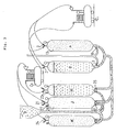
- the supplement of the material for continuous transfer is conducted in Natural Pressure Operation or together with Added Pressure Operation. Now the method is explained according to the Figure 1.
- Alternate Added Pressure Operation is conducted with the compressed air of fixed gauge pressure.
- the supplement of material is conducted through pressure tanks D and E which are specially prepared. The material is pushed into the tanks A and B alternately from the tank D.
- Natural Added Pressure Operation is conducted with the compressed air of the fixed gauge pressure between the tanks D and E. If necessary, Added Pressure Operation is used jointly. The process of supplement of material in Natural Pressure Operation or joint use with Added Pressure Operation strengthens the Alternate Added Pressure Operation between the tanks A and B, and besides high effectiveness of transfer is obtained.
- the material (liquid of the specific gravity 1.0) is transferred continuously to a destination at a level of 100m above the location of the tanks A and B or to a destination 5,000m distant parallel to the ground with the compressed air of 11.0 atm gauge pressure in Alternate Added Pressure Operation between the tanks A and B.
- the supplement of material is conducted in Natural Pressure Operation with 8.33-2.5 atm gauge pressure, and Added Pressure Operation is jointly used, if necessary.
- the tank A and the tank B are each of 1,100 liter capacity.
- the unit transfer of the material is 1,000 liter, so that even when the total amount of liquid is pushed into one of the tanks A and B, there still remains space of 100 liter in that tank.
- the capacity of the tank E is 500 liter.
- the tank B is filled with 1,000 liter of water, and at the upper part of the tank in which 100 liter space remains, the compressed air of 2.0 atm gauge pressure is stored.
- the tank A with the capacity of 1,100 liter, is filled with compressed air of 11.0 atm gauge pressure.
- Alternate Added Pressure is conducted between the tanks A and B by the compressor C1, while the compressor C2 also acts on the air in the tank D to draw up into the tank E. While a fixed volume of liquid, e.g., 337.5 liter of liquid is transferred from tank A or tank B to a destination, the air in the tank D is drawn up between the tank D and the tank E, and then the pressure inside of the tank D drops, whereby 1,000 liter of supplementary liquid fills the tank D. Thus the first step is completed.
- a fixed volume of liquid e.g., 337.5 liter of liquid is transferred from tank A or tank B to a destination
- the air in the tank D is drawn up between the tank D and the tank E, and then the pressure inside of the tank D drops, whereby 1,000 liter of supplementary liquid fills the tank D.
- the level of the liquid in the tank B As the liquid in the tank B is transferred to the destination, the level of the liquid comes down, so that the upper space of the tank B enlarges above 100 liter volume.
- the pressure of the upper space is initially 2.0 atm gauge pressure and then the pressure rises to 11.0 atm gauge pressure, while Added Pressure Operation is continued.
- 11.0 atm gauge pressure of the compressed air in the tank A gradually comes down as the liquid of the tank A is transferred into the tank B.
- Sensing by the level switch 4 at the tank B the instant when 337.5 liter of liquid out of the initial volume of 1,000 liter in the tank B has been transferred, or sensing by utilizing applicable control means the instant when pressure gauge at the tank A indicates 6.5 atm gauge pressure, the first stage is finished.
- Added Pressure Operation between the tanks A and B 337.5 liter out of the 1,000 liter in the tank B transferred to the destination.
- the pressure inside the tank A drops to 6.5 atm gauge pressure, namely prior to the completion of the first stage, the following process, i.e., supplement of 1,000 liter liquid to fill the tank D is conducted.
- the operation of having the tank E draw up the air in the tank D is conducted with the concurrence of Alternate Added Pressure Operation between the tanks A and B.
- the valve 5 of the tank D and the valve 6 of the tank E are opened.
- the compressor C2 operates to push up the compressed air of 2.5 atm gauge pressure in the tank D into the tank E.
- the pressure of the tank D drops rapidly.
- the pressure valve 7 is pushed downward and the supplementary liquid flows into the tank D.
- the compressor C2 continues to draw up the air inside the tank D, while the inflow of the supplementary liquid pushes up the air inside the tank D from the bottom to the upper portion. Accordingly, the operation of the compressor C2 for pushing the air in the tank D into the tank E becomes more and more effective.
- the compressor C2 stops its operation.
- the valve 9 of the tank D and the valve 10 of the tank E are opened.
- the high pressure air in the tank E flows rapidly into the upper space of the tank D.
- the pressure valve 7 is pushed upward, so that the inflow of supplementary liquid is prevented.
- the upper space with 100 liter volume of the tank D and the tank E are both filled with compressed air having 8.33 atm gauge pressure. If necessary from the viewpoint of control, pressure gauges of the tank D and the tank E may sense the instant.
- 1,000 liter of supplementary liquid is already prepared in the tank D, the upper space of which is pressurised at 8.33 atm gauge pressure.
- the liquid of 337.5 liter in the tank B belonging to Added Pressure system is transferred to the destination, and, in the tank A, the initial 11.0 atm gauge pressure due to Added Pressure Operation drops to 6.5 atm gauge pressure.
- the valve 11 at the bottom of the tank A is opened.
- the supplementary liquid in the tank D is pushed strongly into the tank A through the bottom of the tank A by the compressed air of 8.33 atm gauge pressure which is preserved in the upper space of 100 liter volume in the tank D and in the tank E with the capacity of 500 liter volume.
- the efficiency of Alternate Added Pressure Operation between the tanks A and B is improved by the supplement of the supplementary liquid conducted in Natural Added Pressure Operation between the tanks D and E, so that 662.5 liter of liquid left in the tank B is pushed up to a destination with an accelerated speed.
- the level switch at the tank B senses that instant and the valve 3 at the tank B is closed. It is needless to say that the pressure inside the tank B is 11.0 atm gauge pressure, since Added Pressure Operation with 11.0 atm gauge pressure has been completed.
- the tank A is filled with 1,000 liter of supplementary liquid, and, at the upper portion thereof, the space with the capacity of 100 liter is at 2.0 atm gauge pressure.
- the PV value of the tanks A and B is;
- the tank A is filled with 1,000 liter of liquid material, and the upper space with the capacity of 100 liter, is filled with compressed air at 2.0 atm gauge pressure.
- the tank B is filled with compressed air with 11.0 atm gauge pressure.
- Both the tank D and the tank E are filled with compressed air at 2.5 atm gauge pressure.
- Added Pressure Operation between the tanks D and E is also possible.
- the process until the first stage is the same.
- the pipe connected between the valve 9 at the tank D and the valve 10 at the tank E is sufficiently large and in addition Natural Pressure Operation can fully conduct the process, without the need of the compressor C2, arranged for supporting the Added Pressure Operation between the tanks A and B, then there is no need to adopt such Added Pressure Operation. Therefore the adoption of Added Pressure Operation depends on the kinds and properties of liquid material or on the need of more efficiency.
- Added Pressure Operation between the tanks D and E is adopted, then the piping is as illustrated in Figure 1 by dotted line.
- the valve 10 is closed on the way of conducting Natural Pressure Operation between the tanks D and E.
- the compressed air in the tank E is pushed strongly into the tank D, through the compressor C2, from the opened valve 6 to the valve 9 at the tank D.
- the gauge pressure of the tank E drops further, and in inverse proportion thereto the gauge pressure of the tank D rises, thus Added Pressure Operation between the tanks A and B is accelerated.
- the operation of the tank E at negative gauge pressure would decrease the operation efficiency, so that the pressure of the tank E is controlled to drop to the atmospheric level.
- the Alternate Added Pressure Operation between the tanks A and B is supported initially with 1.83 atm pressure difference and finally with 0.5. atm pressure difference.
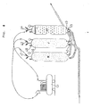
- the present method applies a receiver tank G to Alternate Added Pressure Operation between the tanks A and B. Now the method is explained according to the Figure 2.
- the compressor used in the above Method 1 is a booster compressor which draws up compressed air discharge it as well as the atmospheric air. Both the inlet pressure and the discharge pressure of said booster compressor are controlled to be 11.0 atm gauge pressure in Method 1. However, in actuality, the discharge pressure of the booster compressor is 10.0 atm gauge pressure at maximum, the inlet pressure is lower than that of the discharge pressure. For example, in general, the inlet pressure of a booster compressor is 6.0 atm gauge pressure. In the present method, the booster compressor C1 has the inlet pressure 6.0 atm gauge pressure at maximum and the discharge pressure of 10.0 atm gauge pressure at maximum.
- the tank A with a capacity of 600 liter is filled with compressed air of 10.0 atm gauge pressure.
- the tank B having the same capacity as the tank A is filled with 550 liter of liquid, and in its upper portion compressed air of 1.0 atm gauge pressure is preserved.
- the receiver tank G with the capacity of 600 liter is filled with compressed air of 1.0 atm gauge pressure.
- valve 15 of the tank A and the valve 16 of the tank G are opened, so that the tank A and the tank G are connected.
- the valve 17 of the tank G and the valve 2 of the tank B are opened.
- the compressor C1 the compressed air in the tank B is drawn up to act on the upper space of 50 liter in the tank B for transfer, while the compressor C2 is also actuated, and the compressed air with 2.5 atm gauge pressure in the tank D is drawn up into the tank E.
- the compressor C1 draws up the compressed air with 1.0 atm gauge pressure in the tank G.
- the compressed air with 10.0 atm gauge pressure the tank A flows into the tank G, so that the pressure inside the tank G rises within a range not exceeding 5.5. atm gauge pressure.
- the pressure inside the tank A also drops rapidly.
- the valves 15 and 16, which connect the tank A and G are closed.
- the valve 1 at the tank A is opened, and the compressed air in the tanks A and G, both of which are below 5.5 atm gauge pressure, is pushed into the tank B in Added Pressure Operation.
- the pressure of the compressed air, initially at 1.0 atm gauge pressure, in the upper portion in the tank B rises rapidly.
- valve 5 at the tank D and the valve 6 at the tank E are opened.
- the compressor C2 actuates to push up the compressed air of 2.5 atm gauge pressure in the tank D into the tank E.
- the pressure inside the tank D drops rapidly.
- the valve 7 of the tank D is opened, and supplementary liquid flows into the tank D.
- the valve 7 is closed and the operation of the compressor C2 ceases.
- the valves 5 and 6 are closed, and the valve 9 at the tank D and the valve 10 at the tank E are opened.
- the high pressure air in the tank E flows into the upper portion of the tank D. At this point, the upper portion with the capacity of 50 liter in the tank D and the whole of tank E are both filled with compressed air with 6.78 atm. gauge pressure.
- the valve 11 at the bottom of the tank A is opened, and supplementary liquid flows into the tank A through its bottom.
- the initial gauge pressure of the tank A as a drawing up tank and the inlet pressure from the tank G are both 5.5 atm gauge pressure. Accordingly, at the time when supplementary liquid of 550 liter flows with 6.78 atm gauge pressure from the tank D, the pressure of both of the tanks A and G drops below 5.5 atm gauge pressure within a proper range. Then a supplement process operates to promote the Alternate Added Pressure Operation between the tank A and the tanks G and B.
- the level switch 14 senses that instant, and the valve 3 at the tank B is closed, while the valve 18 at the bottom of the tank A is opened.
- the air pressures in the upper portion with the capacity of 500 liter of the tank A and in the tank G are both 1.0 atm gauge pressure.
- the first stage is completed and the second stage starts.
- the contents of the tanks A and B in the preparatory stage are interchanged. None has changed in other points.
- valve 19 at the tank B and the valve 16 at the tank G are opened to connect the tank B and the tank G.
- the valve 17 at the tank G and the valve 20 at the tank A are opened.
- the compressor C1 the compressed air in the tank G is taken to act on the upper portion with the capacity of 50 liter in the tank A.
- the compressor C2 While conducting Alternate Added Pressure Operation, the compressor C2 also operates as in the case of the first stage. Added Pressure Operation between the tanks D and E is also available.
- valve disposed at the intermediate point of the top of each tank is an inlet valve, which is used when a fixed pressure drops down due to, e.g., blow-by.
- the material (liquid of the specific gravity 1.0) is transferred continuously to a destination at a level of 100m above the tanks A and B or to a place 10,000m distant parallel to the ground with compressed air of 1.0 atm gauge pressure in Alternate Added Pressure Operation between the tank A and B.
- the supplement of the material is conducted with atm gauge pressure 11.0 in a transformed Alternate Added Pressure Operation between the tanks H, J and K.
- All the tanks A, B, H, J, and K have the capacity of 1,100 liter respectively.
- the unit of the transfer is to be 1,000 liter, so that at the upper portion of each tank a space with the capacity of 100 liter remains even when the tank is full of liquid.
- the tank B is filled with 1,000 liter of liquid. At the upper portion thereof, there remains compressed air of 2.0 atm gauge pressure.
- the tank A with the capacity of 1,000 liter is filled with compressed air of 11.0 atm gauge pressure.
- the PV constant of Tank A + Tank B is 13,500.
- the tank H is filled with 1,000 liter of liquid, and at the upper Portion thereof, there remains space at atmospheric pressure, i.e., at zero gauge pressure.
- the tank J is filled with compressed air at atmospheric pressure, and the tank K is filled with compressed air at 11.0 atm gauge pressure.
- the piping from the tank F to the bottom of each tanks H, J and K is arranged for supplementing of liquid.
- a chain of process is explained by each tank.
- the valve 21 at the tank J is opened.
- the air of atmospheric pressure in the tank J is pushed into the upper portion of the tank H.
- the pressure of the tank J is to become negative, but, as the valve 22 at the bottom of the tank J is opened at the moment the valve 21 is opened, the supplementary liquid in the tank F flows by natural flow into the tank J, through the bottom, thereby pushing up the air above.
- the air pushed up is pushed up, through the compressor C2, into the upper portion of the tank H.
- the inflow speed of the supplementary liquid is quite rapid.
- 1,000 liter of supplementary liquid flows into the tank J.
- the tank H As for the tank H, when the air of atmospheric pressure in the tank J is pushed up, through the compressor C2 into the tank H from the valve 23, the pressure of the upper space of the tank H rises up rapidly. And at the moment the pressure gauge senses 10.0 atm gauge pressure, the valve 21 at the tank J is closed, and the valve 24 at the tank K and the valve 25 at the tank H are opened so as to transfer the compressed air of 11.0 atm gauge pressure in the tank K in Added Pressure Operation.
- the compressed air of 11.0 atm gauge pressure in the tank K is transferred in Added Pressure Operation, through the compressor C2, from the valve 24 at the tank K to the valve 23 at the tank H, to act on 1,000 liter liquid in the tank H. Since the upper space with the capacity of 100 liter has already become 10.0 atm gauge pressure and the valve 25 is opened, the supplementary liquid flows, with gauge pressure exceeding the air pressure inside the tank A, into the tank A through the bottom of the tank A. At this point, let us check the progress regarding Alternate Added Pressure Operation between the tanks A and B.
- the upper space with the capacity of 100 liter in the tank B initially contains compressed air at 2.0 atm gauge pressure. Then the compressed air of 11.0 atm gauge in the tank A flows in, and the pressure of the upper space rises immediately up to 11.0 atm gauge pressure. 1,000 liter of liquid is transferred to a destination through the valve 3. In proportion to the volume of the transferred liquid, the pressure inside the tank A drops down from 11.0 atm gauge pressure, and the speed of Added Pressure Operation decreases according to the falling air pressure. To avoid this, supplementary liquid is pushed up, with the gauge pressure not below 11.0 atm, from the bottom of the tank A in order to support Added Pressure Operation between the tanks A and B. This resembles the following. Namely, passenger cars A and B full of passengers ascend a slope with full rotation of engine, while passenger cars H and K with no passengers, having more efficiency, support the above A and B with full rotation of engine.
- the tanks H, J and K in this method can be regarded perfectly as a closed cycle. Namely, in the first stage, the tank J is full of air at atmospheric pressure, and then the tank J succeeds, under atmospheric pressure or full of the atmospheric air, the phase of the tank H in the preparatory stage. Thus, there is no difference with the phase conversion within a closed cycle.
- the valve 25 at the tank H is closed.
- the tank H is filled with compressed air of 11.0 atm gauge pressure
- the pressure of the tank K drops to atmospheric pressure.
- the tank A is filled with 1,000 liter of liquid and the upper space thereof with the capacity of 100 liter is pressurized by compressed air of 2.0 atm gauge pressure.
- the tank B is filled with compressed air of 11.0 atm gauge pressure. This means that the contents of the tanks A and B in the preparatory stage are replaced with each other.
- the tank H is replaced with the tank K, and the tank H is filled with compressed air of 11.0 atm gauge pressure
- the tank J is replaced with the tank H, and the tank J is filled with 1,000 liter of liquid with exception of the upper space with the capacity of 100 liter
- the tank K is replaced with the tank J, and the tank K is filled with atmospheric air.
- the second stage is conducted under the replaced phase, and the process is the same with the first stage.
- the operation process between the tanks A and B returns to the first stage.
- the operation process between the tanks H, J and K enter into the third stage, under such conditions: the tank H is filled with atmospheric air; the tank J is filled with compressed air of 11.0 atm gauge pressure; the tank K is filled with 1,000 liter of liquid, with exception of the upper space with the capacity of 100 liter.
- the third stage is completed, the process at last returns to the conditions of the preparatory stage.
- the following fourth stage is continuously operated under the same process as in the case of the first stage.
- the tank H is filled with 1,000 liter of liquid and at the upper portion, 100 liter of space is occupied with atmospheric air.
- the tank J is also filled with 1,100 liter of atmospheric air.
- the tank K with the capacity of 1,100 liter is filled with compressed air of 11.0 atm gauge pressure (if necessary, the pressure may be varied).
- the upper valve 42 and the lower valve 43 at the tank J, and the upper valve 44 and the lower valve 45 at the tank H are opened. Then the compressor C3 starts to operate. The liquid arriving in the arrow direction from the origin of transfer flows into the tank J through the opened valve 43 at the bottom of the tank J. On the other hand, the atmospheric air in the tank J is drawn up by the compressor C3 and pushed into the upper space of the tank H. Before the pressure inside of the tank J becomes negative, liquid is pushed up through the valve 43 at the bottom of the tank J in Atmospheric Pressure Operation between the tanks H and J with the efficiency nearly as in the case of Alternate Added Pressure Operation, so that the inside of the tank J is at atmospheric pressure or more.
- the 1,000 liter of liquid in the tank H is transferred, through the valve 43, to a next further destination or to a place from where the transferred liquid is distributed.
- the valve 45 at the tank H is closed until the air pressure of the upper space in the tank H becomes 11.0 atm gauge pressure.
- the level switch 46 senses that instant, and the valves 42 and 43 are closed. Then the valve 47 at the tank K is opened and compressed air of 11.0 atm gauge pressure is transferred to the tank H in Added Pressure Operation.
- valve 48 is opened until the upper space reaches atmospheric pressure.
- the valve 45 is closed. At that point, if the pressure of the tank H does not reach gauge pressure 11.0, Alternate Added pressure Operation is conducted further until the pressure in the tank H reaches 11.0 atm gauge pressure. Such reduction of pressure may occurr in the tank H because the pressure of the compressed air used for Alternate Added Pressure Operation is higher than necessary. Accordingly, the initial gauge pressure of the tank K should be decreased to the level that is necessary and sufficient for transfer.
- the first stage is completed through the above processes.
- the phase of the tank H is replaced with the tank K, and the phase of the tank K is replaced with the tank J.
- the second stage starts by repeating the same process, whereby transfer distance can be further extended and also the distribution of the material can be attained with high effectiveness.
- the continuous operation in this method is conducted in two systems.
- the one system includes the tanks A and B or the tanks A, B and D, which are for transfer operation.
- the other system includes the tanks D and E or the tanks H, J and K, which are for continuous supplement. These tanks are controlled by computers such as micro computers or micro processors utilizing fuzzy function.
- the liquid material as the specific gravity, viscosity, the forms of substances included in the liquid and the content ratio thereof, values of friction and resistance etc. are calculated in accordance with hydrodynamics and experiments. After that, the values obtained are memorized in computers.
- the sensor senses properties and forms of the liquid. According to the memories and operation of the computers, the pressure and the volume of transfer of each tank in the two systems are controlled to be best suited. The change of the volume of the treated liquid during the continuous operation in extended time is also able to be dealt with properly by utilizing software developed.
- Newtonian fluid and slurry of non-Newtonian fluid type as well may be transferred in this method.
- Solid substances included in the fluid are also acceptable for this method as long as the sizes of the solid substances are smaller than the diameters of valves and pipes. Accordingly, stirring is required for some kinds of liquid in transfer.
- said process is described in the aforesaid International Publication No. WO 90/03322 wherein compressed air is pushed, through a plurality of divergent pipes, from the bottom of a tank where stirring is conducted. Bubbles risen up from the bottom of the tank crush the precipitated or coagulated substances, then compressed air preserved at the upper portion of the tank push up the stirred liquid into an another pipe connected to the bottom of the tank.
Landscapes
- Engineering & Computer Science (AREA)
- Mechanical Engineering (AREA)
- Physics & Mathematics (AREA)
- Fluid Mechanics (AREA)
- Jet Pumps And Other Pumps (AREA)
- Electrical Discharge Machining, Electrochemical Machining, And Combined Machining (AREA)
- Separation By Low-Temperature Treatments (AREA)
- Printing Methods (AREA)
- Screen Printers (AREA)
- Pipeline Systems (AREA)
- Fats And Perfumes (AREA)
Claims (4)
- Verfahren zum Fördern von Material unter Verwendung von Luft als Fördermedium, umfassend die wiederholten Schritte desFörderns von Material von einem ersten Druckbehälter (A,B) durch den Druck von Druckluft;Zurückbehaltens der Druckluft in dem ersten Druckbehälter (A,B) als Ersatz für das geförderte Material;Nehmens der Druckluft, die nach dem einen Förderschritt zurückbehalten wurde, aus dem ersten Druckbehälter (A,B) und, während dies geschieht, Einführens weiteren Materials, das in einem späteren Förderschritt zu übertragen ist, in den ersten Druckbehälter (A,B); undEinführens der zurückbehaltenen Druckluft aus dem ersten Druckbehälter (A,B) als Fördermedium in einen zweiten Druckbehälter (B,A), der das im nächsten Förderschritt zu fördernde Material enthält, wobei der Druck der zurückbehaltenen Druckluft auf das zu fördernde Medium einwirkt und die innere Energie der Druckluft Energie für den nächsten Förderschritt liefert;
wobei das weitere Material in den ersten Druckbehälter (A) von einem dritten Druckbehälter (D) durch den Druck der Druckluft eingeführt wird. - Verfahren nach Anspruch 1, umfassend den wiederholten Schritt des Förderns von Luft von einem dritten Druckbehälter (D) in einen vierten Druckbehälter (E), um Material in den dritten Druckbehälter (D) zu ziehen, und des Förderns der Luft vom vierten Druckbehälter in den dritten Druckbehälter, wobei das Material vom dritten Druckbehälter (D) ausgestoßen und das Material in den ersten oder zweiten Druckbehälter eingeführt wird.
- Verfahren nach Anspruch 1, bei dem der erste Druckbehälter (H) anfänglich zu förderndes Material enthält, der zweite Druckbehälter (J) anfänglich Luft vom im wesentlichen Umgebungsdruck enthält, und ein weiterer Druckbehälter (K) anfänglich Druckluft enthält, wobei das Verfahren die zyklisch wiederholten Schritte desEinführens von Material in den zweiten Druckbehälter (J), während die Luft aus diesem Behälter in den ersten Druckbehälter (H) gedrückt wird, undTransports des Materials vom ersten Druckbehälter (H) durch den Druck der Druckluft aus dem weiteren Druckbehälter (K)
umfaßt,nach welchen Schritten der zweite Druckbehälter (J) zu förderndes Material, der weitere Druckbehälter (K) Luft von im wesentlichen Umgebungsdruck enthält, und der erste Druckbehälter (H) Druckluft enthält. - Verfahren zum Transport von Material, umfassend ein Transportieren von Material von einem ersten Ort zu einem zweiten Ort durch ein Verfahren, wie in Anspruch 1 oder Anspruch 2 beansprucht, und ein Transportieren des Materials vom zweiten Ort zu einem dritten Ort durch ein Verfahren, wie in Anspruch 3 beansprucht.
Applications Claiming Priority (2)
| Application Number | Priority Date | Filing Date | Title |
|---|---|---|---|
| JP3280118A JP2880338B2 (ja) | 1991-10-25 | 1991-10-25 | 圧搾気体による被移送物の圧送方式 |
| JP280118/91 | 1991-10-25 |
Publications (2)
| Publication Number | Publication Date |
|---|---|
| EP0541278A1 EP0541278A1 (de) | 1993-05-12 |
| EP0541278B1 true EP0541278B1 (de) | 1998-07-22 |
Family
ID=17620585
Family Applications (1)
| Application Number | Title | Priority Date | Filing Date |
|---|---|---|---|
| EP92309754A Expired - Lifetime EP0541278B1 (de) | 1991-10-25 | 1992-10-23 | Verfahren zum Fördern von Fluidum mittels Druckluft |
Country Status (7)
| Country | Link |
|---|---|
| US (2) | US5445500A (de) |
| EP (1) | EP0541278B1 (de) |
| JP (1) | JP2880338B2 (de) |
| KR (1) | KR0134949B1 (de) |
| AT (1) | ATE168661T1 (de) |
| DE (1) | DE69226329T2 (de) |
| TW (1) | TW300213B (de) |
Families Citing this family (12)
| Publication number | Priority date | Publication date | Assignee | Title |
|---|---|---|---|---|
| DK1036083T5 (da) * | 1997-10-16 | 2005-04-04 | Pliva Istrazivacki Inst D O O | Nye 9A-azalider |
| US7056893B2 (en) * | 1999-03-31 | 2006-06-06 | Insite Vision, Inc. | Topical treatment for prevention of ocular infections |
| US6239113B1 (en) * | 1999-03-31 | 2001-05-29 | Insite Vision, Incorporated | Topical treatment or prevention of ocular infections |
| CN1274050A (zh) * | 1999-05-14 | 2000-11-22 | 杨双来 | 高压气泵 |
| US9043212B2 (en) * | 2002-04-02 | 2015-05-26 | Verizon Patent And Licensing Inc. | Messaging response system providing translation and conversion written language into different spoken language |
| US6688340B1 (en) | 2002-11-04 | 2004-02-10 | Adam Awad | Automotive power steering flush system and methods of use |
| US6772803B2 (en) * | 2002-11-04 | 2004-08-10 | Adam Awad | Power steering fluid exchange system and method of use |
| US20060046970A1 (en) * | 2004-08-31 | 2006-03-02 | Insite Vision Incorporated | Topical otic compositions and methods of topical treatment of prevention of otic infections |
| JP5638486B2 (ja) * | 2011-08-09 | 2014-12-10 | 三井海洋開発株式会社 | 気泡リフトシステム、及び、気泡リフト方法 |
| DE102013106592B4 (de) * | 2013-06-24 | 2016-12-01 | Pard Hardware Industrial Co., Ltd. | Reinigungsmittelrecyclingvorrichtung und Arbeitstischvorrichtung mit der Reinigungsmittelrecyclingvorrichtung |
| US20170016458A1 (en) * | 2015-07-15 | 2017-01-19 | Materials and Technologies, Corp. | Simple Positive Displacement Pump Suitable for Pharmaceutical, Chemical, Biological, Viscous, Dense, Particulate Laden Fluids and Other Demanding Applications |
| KR102841558B1 (ko) * | 2022-04-21 | 2025-08-04 | 한국전자통신연구원 | 가상환경과 실제환경 간 학습장치 행동의 동기화 방법 및 장치 |
Family Cites Families (35)
| Publication number | Priority date | Publication date | Assignee | Title |
|---|---|---|---|---|
| US1600505A (en) * | 1921-10-01 | 1926-09-21 | Sullivan Machinery Co | Control mechanism |
| US2077898A (en) * | 1934-06-14 | 1937-04-20 | Rolff Friedrich | Container for granular and like materials |
| US3005417A (en) * | 1957-04-26 | 1961-10-24 | United States Steel Corp | Pneumatic system for pumping liquid |
| US3082698A (en) * | 1959-04-09 | 1963-03-26 | Techno Corp | Pump operated on pressure differential |
| US3333901A (en) * | 1966-02-28 | 1967-08-01 | Alberta Res Council | Method and apparatus for transporting package material in a pipeline |
| US3328089A (en) * | 1966-02-28 | 1967-06-27 | Alberta Res Council | Method and apparatus for transporting package material in a pipeline |
| US3552884A (en) * | 1967-07-20 | 1971-01-05 | Giovanni Faldi | Fluid pumping station working on the compressed air principle with partial recovery and re-cycling of the air |
| US3689045A (en) * | 1971-06-03 | 1972-09-05 | Earl E Coulter | Pulverized fuel delivery system for a blast furnace |
| US3762773A (en) * | 1972-06-30 | 1973-10-02 | W Schroeder | Method and apparatus for feeding finely divided solids to a pressurized gas or gasliquid solids system |
| US3829246A (en) * | 1973-01-22 | 1974-08-13 | B Hancock | System for raising and using water |
| US3864060A (en) * | 1973-02-21 | 1975-02-04 | Nasa | Automatic liquid inventory collecting and dispensing unit |
| US3883269A (en) * | 1973-11-01 | 1975-05-13 | Robert C Wolff | Liquid transfer system |
| US4111492A (en) * | 1976-02-03 | 1978-09-05 | Joseph Mraz | Pneumatic conveying apparatus and method |
| JPS587571B2 (ja) * | 1978-02-20 | 1983-02-10 | 日立プラント建設株式会社 | 粉粒体輸送装置の制御方法 |
| JPS599440B2 (ja) * | 1978-04-17 | 1984-03-02 | 三菱重工業株式会社 | 浚液装置 |
| JPS60293B2 (ja) * | 1979-04-24 | 1985-01-07 | 三興空気装置株式会社 | 双筒高圧式空気輸送装置 |
| JPS56113616A (en) * | 1980-02-08 | 1981-09-07 | Hitachi Ltd | Hydraulic hoist |
| US4381897A (en) * | 1980-10-06 | 1983-05-03 | Krupp Polysius Ag | Installation for transporting fine-grained material |
| US4507056A (en) * | 1981-09-11 | 1985-03-26 | Logic Devices, Inc. | Liquid circulation apparatus and method |
| US4408960A (en) * | 1981-09-11 | 1983-10-11 | Logic Devices, Inc. | Pneumatic method and apparatus for circulating liquids |
| IT1172131B (it) * | 1981-12-04 | 1987-06-18 | Colgate Palmolive Spa | Dispositivo selettore dosatore ed erogatore di liquidi in particolare liquidi trattamento per lavatrichi industriali |
| JPS59172328A (ja) * | 1983-03-16 | 1984-09-29 | Hitachi Ltd | スラリ−連続圧送装置 |
| DE3439251A1 (de) * | 1984-10-26 | 1986-04-30 | KBI Klöckner-Becorit Industrietechnik GmbH, 4224 Hünxe | Vorrichtung zum aufgeben von schuettgut an eine pneumatische foerderleitung |
| SU1207942A1 (ru) * | 1984-11-11 | 1986-01-30 | Solomatin Oleg M | Питатель пневмотранспортной установки |
| US4685840A (en) * | 1985-08-02 | 1987-08-11 | Wolff Robert C | Method of transporting large diameter particulate matter |
| BR8607110A (pt) * | 1986-03-11 | 1988-02-23 | Banyaszati Fejlesztesi Intezet | Dispositivo de acionamento para alimentadores de tubulacao-camara de equipamentos de transporte hidraulica |
| SE452289B (sv) * | 1986-03-11 | 1987-11-23 | Billy Jacquet | Kombinationsverktyg for cykelreparationer |
| US4818187A (en) * | 1986-05-21 | 1989-04-04 | Daniel Scampini | Fluid exchange pump |
| SU1402518A1 (ru) * | 1986-07-22 | 1988-06-15 | Всесоюзный Научно-Исследовательский И Проектно-Изыскательский Институт Трубопроводного Гидротранспорта | Способ подачи сыпучих материалов в пульповод |
| SU1418215A1 (ru) * | 1987-02-11 | 1988-08-23 | Всесоюзный Научно-Исследовательский И Проектно-Изыскательский Институт Трубопроводного Гидротранспорта | Установка дл гидравлического транспортировани сыпучих материалов |
| US4765779A (en) * | 1987-02-26 | 1988-08-23 | Organ William L | Apparatus and method for charging canisters with granular carbon |
| SU1421645A1 (ru) * | 1987-03-09 | 1988-09-07 | Всесоюзный Научно-Исследовательский И Проектно-Изыскательский Институт Трубопроводного Гидротранспорта | Гидротранспортна установка |
| SU1525339A1 (ru) * | 1988-03-09 | 1989-11-30 | Проектный И Научно-Исследовательский Институт "Мосгазниипроект" | Пневматический насос замещени |
| KR950014421B1 (ko) * | 1988-09-19 | 1995-11-27 | 모리-구미 컴패니 리미티드 | 압축공기를 이용한 피이송물의 압송방법 |
| US4938637A (en) * | 1989-06-09 | 1990-07-03 | Lybecker G Wayne | Method and apparatus for bottom loading a pneumatic transport pressure vessel |
-
1991
- 1991-10-25 JP JP3280118A patent/JP2880338B2/ja not_active Expired - Fee Related
-
1992
- 1992-10-23 AT AT92309754T patent/ATE168661T1/de not_active IP Right Cessation
- 1992-10-23 DE DE69226329T patent/DE69226329T2/de not_active Expired - Fee Related
- 1992-10-23 EP EP92309754A patent/EP0541278B1/de not_active Expired - Lifetime
- 1992-10-26 KR KR1019920019723A patent/KR0134949B1/ko not_active Expired - Fee Related
-
1993
- 1993-01-16 TW TW082100266A patent/TW300213B/zh active
- 1993-10-18 US US08/137,217 patent/US5445500A/en not_active Expired - Fee Related
-
1995
- 1995-03-16 US US08/405,292 patent/US5520518A/en not_active Expired - Fee Related
Also Published As
| Publication number | Publication date |
|---|---|
| KR0134949B1 (ko) | 1998-04-25 |
| JP2880338B2 (ja) | 1999-04-05 |
| DE69226329T2 (de) | 1999-04-08 |
| US5520518A (en) | 1996-05-28 |
| DE69226329D1 (de) | 1998-08-27 |
| ATE168661T1 (de) | 1998-08-15 |
| JPH06239455A (ja) | 1994-08-30 |
| EP0541278A1 (de) | 1993-05-12 |
| US5445500A (en) | 1995-08-29 |
| TW300213B (de) | 1997-03-11 |
| KR930007782A (ko) | 1993-05-20 |
Similar Documents
| Publication | Publication Date | Title |
|---|---|---|
| EP0541278B1 (de) | Verfahren zum Fördern von Fluidum mittels Druckluft | |
| US6652243B2 (en) | Method and apparatus for filling a storage vessel with compressed gas | |
| CN1668234A (zh) | 用于制备饮料的设备 | |
| US6792981B1 (en) | Method and apparatus for filling a pressure vessel having application to vehicle fueling | |
| CN101010241A (zh) | 预留空间气体移除的液体分配方法和系统 | |
| US5139390A (en) | Pump and method for drawing vapor from a storage tank without forcibly drawing the vapor from the tank | |
| MXPA06008420A (es) | Bomba de ariete hidraulico. | |
| US5364208A (en) | Method of transferring objects with compressed air | |
| US6957567B2 (en) | Method and system for the controlled application of fluid pressure to a load, especially for pressure testing pipe | |
| US5651389A (en) | Method and apparatus for controlling tank vapors | |
| US5348197A (en) | Aerosol container having a side coupled pump module | |
| US6857944B2 (en) | Method for filling a pressure container and device for producing a jet of a suspension | |
| US5899366A (en) | Leak-resistant hand-pump spray bottle | |
| US5988991A (en) | Simplified energy transforming structure | |
| WO2020053486A1 (en) | Fluid pump | |
| CN87103050A (zh) | 水压气压抽水机 | |
| CN1434241A (zh) | 恒压充放气体容器 | |
| CN206111448U (zh) | 一种双作用计量输送泵 | |
| WO1996022517A1 (en) | Sampling bottle arrangement | |
| US7261523B2 (en) | Pump system for delivering pressurized liquid | |
| EP0394466B1 (de) | Gezwungenes zufuhrsystem für materialien, die druckluft verwenden | |
| RU2146218C1 (ru) | Устройство для транспортирования нефти | |
| JP2888574B2 (ja) | 圧搾空気を利用した被移送物の圧送方式 | |
| CN2778787Y (zh) | 一种液体灌装装置 | |
| SU1558796A1 (ru) | Установка дл хранени нефти и нефтепродуктов |
Legal Events
| Date | Code | Title | Description |
|---|---|---|---|
| PUAI | Public reference made under article 153(3) epc to a published international application that has entered the european phase |
Free format text: ORIGINAL CODE: 0009012 |
|
| AK | Designated contracting states |
Kind code of ref document: A1 Designated state(s): AT BE CH DE DK ES FR GB GR IE IT LI LU MC NL PT SE |
|
| 17P | Request for examination filed |
Effective date: 19930705 |
|
| 17Q | First examination report despatched |
Effective date: 19950217 |
|
| GRAG | Despatch of communication of intention to grant |
Free format text: ORIGINAL CODE: EPIDOS AGRA |
|
| GRAG | Despatch of communication of intention to grant |
Free format text: ORIGINAL CODE: EPIDOS AGRA |
|
| GRAH | Despatch of communication of intention to grant a patent |
Free format text: ORIGINAL CODE: EPIDOS IGRA |
|
| GRAH | Despatch of communication of intention to grant a patent |
Free format text: ORIGINAL CODE: EPIDOS IGRA |
|
| GRAA | (expected) grant |
Free format text: ORIGINAL CODE: 0009210 |
|
| AK | Designated contracting states |
Kind code of ref document: B1 Designated state(s): AT BE CH DE DK ES FR GB GR IE IT LI LU MC NL PT SE |
|
| PG25 | Lapsed in a contracting state [announced via postgrant information from national office to epo] |
Ref country code: NL Free format text: LAPSE BECAUSE OF FAILURE TO SUBMIT A TRANSLATION OF THE DESCRIPTION OR TO PAY THE FEE WITHIN THE PRESCRIBED TIME-LIMIT Effective date: 19980722 Ref country code: LI Free format text: LAPSE BECAUSE OF FAILURE TO SUBMIT A TRANSLATION OF THE DESCRIPTION OR TO PAY THE FEE WITHIN THE PRESCRIBED TIME-LIMIT Effective date: 19980722 Ref country code: IT Free format text: LAPSE BECAUSE OF FAILURE TO SUBMIT A TRANSLATION OF THE DESCRIPTION OR TO PAY THE FEE WITHIN THE PRE;WARNING: LAPSES OF ITALIAN PATENTS WITH EFFECTIVE DATE BEFORE 2007 MAY HAVE OCCURRED AT ANY TIME BEFORE 2007. THE CORRECT EFFECTIVE DATE MAY BE DIFFERENT FROM THE ONE RECORDED.SCRIBED TIME-LIMIT Effective date: 19980722 Ref country code: GR Free format text: LAPSE BECAUSE OF FAILURE TO SUBMIT A TRANSLATION OF THE DESCRIPTION OR TO PAY THE FEE WITHIN THE PRESCRIBED TIME-LIMIT Effective date: 19980722 Ref country code: ES Free format text: THE PATENT HAS BEEN ANNULLED BY A DECISION OF A NATIONAL AUTHORITY Effective date: 19980722 Ref country code: CH Free format text: LAPSE BECAUSE OF FAILURE TO SUBMIT A TRANSLATION OF THE DESCRIPTION OR TO PAY THE FEE WITHIN THE PRESCRIBED TIME-LIMIT Effective date: 19980722 Ref country code: BE Free format text: LAPSE BECAUSE OF FAILURE TO SUBMIT A TRANSLATION OF THE DESCRIPTION OR TO PAY THE FEE WITHIN THE PRESCRIBED TIME-LIMIT Effective date: 19980722 Ref country code: AT Free format text: LAPSE BECAUSE OF FAILURE TO SUBMIT A TRANSLATION OF THE DESCRIPTION OR TO PAY THE FEE WITHIN THE PRESCRIBED TIME-LIMIT Effective date: 19980722 |
|
| REF | Corresponds to: |
Ref document number: 168661 Country of ref document: AT Date of ref document: 19980815 Kind code of ref document: T |
|
| REG | Reference to a national code |
Ref country code: CH Ref legal event code: EP |
|
| REF | Corresponds to: |
Ref document number: 69226329 Country of ref document: DE Date of ref document: 19980827 |
|
| PG25 | Lapsed in a contracting state [announced via postgrant information from national office to epo] |
Ref country code: SE Free format text: LAPSE BECAUSE OF FAILURE TO SUBMIT A TRANSLATION OF THE DESCRIPTION OR TO PAY THE FEE WITHIN THE PRESCRIBED TIME-LIMIT Effective date: 19981022 Ref country code: PT Free format text: LAPSE BECAUSE OF FAILURE TO SUBMIT A TRANSLATION OF THE DESCRIPTION OR TO PAY THE FEE WITHIN THE PRESCRIBED TIME-LIMIT Effective date: 19981022 Ref country code: DK Free format text: LAPSE BECAUSE OF FAILURE TO SUBMIT A TRANSLATION OF THE DESCRIPTION OR TO PAY THE FEE WITHIN THE PRESCRIBED TIME-LIMIT Effective date: 19981022 |
|
| PG25 | Lapsed in a contracting state [announced via postgrant information from national office to epo] |
Ref country code: LU Free format text: LAPSE BECAUSE OF NON-PAYMENT OF DUE FEES Effective date: 19981023 Ref country code: IE Free format text: LAPSE BECAUSE OF NON-PAYMENT OF DUE FEES Effective date: 19981023 |
|
| REG | Reference to a national code |
Ref country code: IE Ref legal event code: FG4D |
|
| ET | Fr: translation filed | ||
| NLV1 | Nl: lapsed or annulled due to failure to fulfill the requirements of art. 29p and 29m of the patents act | ||
| REG | Reference to a national code |
Ref country code: CH Ref legal event code: PL |
|
| PG25 | Lapsed in a contracting state [announced via postgrant information from national office to epo] |
Ref country code: MC Free format text: LAPSE BECAUSE OF NON-PAYMENT OF DUE FEES Effective date: 19990430 |
|
| PLBE | No opposition filed within time limit |
Free format text: ORIGINAL CODE: 0009261 |
|
| 26N | No opposition filed | ||
| REG | Reference to a national code |
Ref country code: IE Ref legal event code: MM4A |
|
| REG | Reference to a national code |
Ref country code: GB Ref legal event code: 732E |
|
| REG | Reference to a national code |
Ref country code: FR Ref legal event code: TP |
|
| REG | Reference to a national code |
Ref country code: GB Ref legal event code: IF02 |
|
| PGFP | Annual fee paid to national office [announced via postgrant information from national office to epo] |
Ref country code: FR Payment date: 20041008 Year of fee payment: 13 |
|
| PGFP | Annual fee paid to national office [announced via postgrant information from national office to epo] |
Ref country code: GB Payment date: 20041020 Year of fee payment: 13 |
|
| PGFP | Annual fee paid to national office [announced via postgrant information from national office to epo] |
Ref country code: DE Payment date: 20041021 Year of fee payment: 13 |
|
| PG25 | Lapsed in a contracting state [announced via postgrant information from national office to epo] |
Ref country code: GB Free format text: LAPSE BECAUSE OF NON-PAYMENT OF DUE FEES Effective date: 20051023 |
|
| PG25 | Lapsed in a contracting state [announced via postgrant information from national office to epo] |
Ref country code: DE Free format text: LAPSE BECAUSE OF NON-PAYMENT OF DUE FEES Effective date: 20060503 |
|
| GBPC | Gb: european patent ceased through non-payment of renewal fee |
Effective date: 20051023 |
|
| PG25 | Lapsed in a contracting state [announced via postgrant information from national office to epo] |
Ref country code: FR Free format text: LAPSE BECAUSE OF NON-PAYMENT OF DUE FEES Effective date: 20060630 |
|
| REG | Reference to a national code |
Ref country code: FR Ref legal event code: ST Effective date: 20060630 |