EP0540919B1 - Tourillon pour rouleaux de guidage de papier dans les rotatives d'impression - Google Patents
Tourillon pour rouleaux de guidage de papier dans les rotatives d'impression Download PDFInfo
- Publication number
- EP0540919B1 EP0540919B1 EP92117688A EP92117688A EP0540919B1 EP 0540919 B1 EP0540919 B1 EP 0540919B1 EP 92117688 A EP92117688 A EP 92117688A EP 92117688 A EP92117688 A EP 92117688A EP 0540919 B1 EP0540919 B1 EP 0540919B1
- Authority
- EP
- European Patent Office
- Prior art keywords
- bearing journal
- bearing
- region
- bore
- blind bore
- Prior art date
- Legal status (The legal status is an assumption and is not a legal conclusion. Google has not performed a legal analysis and makes no representation as to the accuracy of the status listed.)
- Expired - Lifetime
Links
Images
Classifications
-
- B—PERFORMING OPERATIONS; TRANSPORTING
- B65—CONVEYING; PACKING; STORING; HANDLING THIN OR FILAMENTARY MATERIAL
- B65H—HANDLING THIN OR FILAMENTARY MATERIAL, e.g. SHEETS, WEBS, CABLES
- B65H23/00—Registering, tensioning, smoothing or guiding webs
- B65H23/04—Registering, tensioning, smoothing or guiding webs longitudinally
- B65H23/044—Sensing web tension
-
- B—PERFORMING OPERATIONS; TRANSPORTING
- B41—PRINTING; LINING MACHINES; TYPEWRITERS; STAMPS
- B41F—PRINTING MACHINES OR PRESSES
- B41F13/00—Common details of rotary presses or machines
- B41F13/02—Conveying or guiding webs through presses or machines
-
- B—PERFORMING OPERATIONS; TRANSPORTING
- B41—PRINTING; LINING MACHINES; TYPEWRITERS; STAMPS
- B41F—PRINTING MACHINES OR PRESSES
- B41F13/00—Common details of rotary presses or machines
- B41F13/08—Cylinders
- B41F13/24—Cylinder-tripping devices; Cylinder-impression adjustments
- B41F13/26—Arrangement of cylinder bearings
-
- F—MECHANICAL ENGINEERING; LIGHTING; HEATING; WEAPONS; BLASTING
- F16—ENGINEERING ELEMENTS AND UNITS; GENERAL MEASURES FOR PRODUCING AND MAINTAINING EFFECTIVE FUNCTIONING OF MACHINES OR INSTALLATIONS; THERMAL INSULATION IN GENERAL
- F16C—SHAFTS; FLEXIBLE SHAFTS; ELEMENTS OR CRANKSHAFT MECHANISMS; ROTARY BODIES OTHER THAN GEARING ELEMENTS; BEARINGS
- F16C11/00—Pivots; Pivotal connections
- F16C11/02—Trunnions; Crank-pins
-
- Y—GENERAL TAGGING OF NEW TECHNOLOGICAL DEVELOPMENTS; GENERAL TAGGING OF CROSS-SECTIONAL TECHNOLOGIES SPANNING OVER SEVERAL SECTIONS OF THE IPC; TECHNICAL SUBJECTS COVERED BY FORMER USPC CROSS-REFERENCE ART COLLECTIONS [XRACs] AND DIGESTS
- Y10—TECHNICAL SUBJECTS COVERED BY FORMER USPC
- Y10T—TECHNICAL SUBJECTS COVERED BY FORMER US CLASSIFICATION
- Y10T403/00—Joints and connections
- Y10T403/70—Interfitted members
- Y10T403/7062—Clamped members
- Y10T403/7064—Clamped members by wedge or cam
- Y10T403/7066—Clamped members by wedge or cam having actuator
- Y10T403/7067—Threaded actuator
- Y10T403/7069—Axially oriented
Definitions
- the invention relates to a bearing journal for paper guide rollers of rotary printing presses according to the preamble of claim 1.
- a device for controlling the web tension in web-fed rotary printing machines in which a paper guide roller is arranged between two printing units, which have strain gauges in the bearing journals, which are provided for measuring higher-frequency tension fluctuations of the paper web.
- the measured values coming from the strain gauges are converted into electrical quantities, displayed by a display instrument and fed to a switching device which triggers various signals and control processes in order to compensate for the voltage fluctuations in the paper web.
- the bearing journals are fixed against the machine frame by means of nuts and locknuts.
- This mounting of the trunnion in the machine frame is disadvantageous in that two people are required when fixing the trunnion, which are required on both sides of the machine frame. Furthermore, when setting the Bearing pin the risk of twisting it. However, the journals should assume a certain position, which is determined by the resultant of the forces from the wrapping of the paper web around the guide roller and the arrangement of the strain gauges. This position is then no longer guaranteed or only with great effort due to the twisting. The greatest effectiveness of the strain gauges is only given if they are arranged in a plane which is penetrated at right angles by the resultant of the forces mentioned. Another disadvantage is that a plurality of bearing journals must be kept in stock in terms of their length, corresponding to the thickness of the side wall of the machine frame.
- rollers used for tensioning the paper web in rotary printing presses in which the rollers have bearing journals which are equipped with strain gauges in order to accomplish the web tension measurement.
- the trunnions are held on the pedestals of the machine frame.
- the disadvantage here is that the bearing blocks for the trunnions have a play in their fasteners, so that inaccuracies can occur during assembly of the rollers, which easily lead to the paper web running.
- the invention has for its object a universally usable, mounted in the machine frame bearing journal for paper guide rollers To create rotary printing machines, in particular for receiving strain gauges for controlling the web tension, which can be easily rotated and assembled and can be fixed in the machine frame regardless of the thickness of the side wall of the machine frame.
- the bearing journal can be fixed in the machine frame, regardless of the arrangement of a flange or a thread, ie a bearing journal according to the invention of a certain length can be used in machine frames of different thicknesses.
- the bearing journal according to the invention is easily rotatable up to 360 °, which is always desirable when the strain gauges of two bearing journals interact in a bridge circuit.
- the bearing journal is easy to handle by an operator during assembly from the outside of the machine frame. As a result of the use of wedges with an angle of 15 °, the same is self-locking, so that an independent loosening of the bearing journal is not possible.
- the self-locking of the wedges can be released again in a simple manner by means of an adjusting screw.
- the arrangement of the bearing of the paper guide roller in the bores of a machine frame means that the possibility of an inaccurate installation of a paper guide roller and thus a running of the paper web is almost impossible.
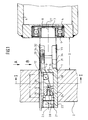
- a bearing journal 1 according to the invention is shown in longitudinal section, which on the one hand can be clamped in a bore in the side wall 2 of a machine frame and on the other hand engages with its twist 3 in a ball bearing 4 of a paper guide roller 6.
- the self-aligning ball bearing 4 is limited in the axial direction on the one hand by a cover plate 7 and on the other hand by a spacer ring 8.
- the right side of the paper guide roller 6, not shown, is also mounted in a side wall of the machine frame, not shown, via a bearing pin, not shown.
- the side of the bearing journal 1 located in the side wall 2 has a clamping area C, which is one in the axial direction runs blind hole 9, which with three radially directed in the direction of the shell 11 of the journal 1 and axially extending slots 12; 13; 14 communicates.
- the blind hole 9 of the clamping area C there are two wedges 16 which can be moved relative to one another; 17, whose pitch angle ⁇ is approximately 15 °.
- By pressure on the end faces 18; 19 of the wedges 16; 17 these are moved towards one another and spread the slots 12; 13; 14; on, so that in area C there is a clamping effect of area C of the journal 1 in the bore of the side wall 2.
- the wedge 16 is supported with its end face 18 on the bottom of the blind hole 9.
- the end face 19 of the wedge 17 abuts a pressure screw 21 which is guided in an internal thread 22 at the beginning of the blind hole 9.
- ⁇ of approximately 15 °
- the wedges 16 self-adhere; 17 in a row.
- the pressure screw 21 is loosened by a number of threads by means of an Allen key, and subsequently an adjusting screw 24 is inserted into a bore 23 running in the axial direction in the pressure screw 21, which in a threaded bore 26 is screwed in.
- the threaded bore 26 is located in the end face 19 of the wedge 17 and extends in the axial direction in the alignment of the center line 27 of the bearing pin 1.
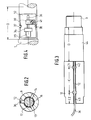
- the strain gauges 29; 31 In area D of the journal 1, the strain gauges 29; 31 arranged (see also Fig. 4).
- the strain gauges 29; 31 are each located in opposite recesses 32; 33 of the lateral surface 11.
- the bottom surfaces of the recesses 32; 33 run parallel to each other.
- the recess 32 has soldering support points 34, which exclude the strain gauges 29; 31 connects to the wires of a cable 36.
- the cable 36 is intercepted by a cable clamp 39 which is held by a screw 41.
- the cable 36 is in the areas C1 and C2 of the journal 1 in a groove 42 extending in the axial direction in the jacket 11; 43 and between the grooves 42; 43 out in the slot 12 so that it can be fed to a measuring device, not shown.
- the recesses 32; 33 can be installed after the electrical devices 29; 31; 34; 36; 39; 41 be carried out by means of a suitable insulating material and be provided with a protective sleeve 44.
- the bearing journal 1 is connected via the electrical cable 36 to electrical devices, not shown.
- the electrical cable 36 can be led to a converter in which the electrical quantities are converted, displayed by display instruments and fed to a switching device.
- this switching device can trigger the triggering of acoustic and optical warning signals, so that correction control can be carried out manually.
- regulation of the paper web tension can then also be initiated via the computer of the rotary printing press.
Landscapes
- Engineering & Computer Science (AREA)
- Mechanical Engineering (AREA)
- General Engineering & Computer Science (AREA)
- Rotary Presses (AREA)
- Inking, Control Or Cleaning Of Printing Machines (AREA)
- Standing Axle, Rod, Or Tube Structures Coupled By Welding, Adhesion, Or Deposition (AREA)
Claims (6)
- Tourillon de palier pour rouleaux de guidage de papier de machines à imprimer rotatives, en particulier pour recevoir des jauges extensométriques destinées à la commande de la tension de la bande de papier. La valeur de mesure étant amplifiée par des convertisseurs, la valeur de mesure étant affichée et en cas d'écart par rapport à une valeur de consigne étant déclenché un signal d'alarme et les tourillons de palier étant disposés à demeure sur le bâti, caractérisé en ce que le tourillon de palier (1) présente une zone de serrage (C) pour la paroi latérale (2) du bâti machine, qui comporte un trou borgne (9) s'étendant en direction axiale, relié par trois fentes (12; 13; 14), orientées radialement dans la direction de l'enveloppe (11) du tourillon de palier (1) et s'étendant en direction axiale, en ce que le trou borgne (9) reçoit deux clavettes (16; 17), déplaçables l'une par rapport à l'autre et dont les faces frontales (18; 19) prennent appui tant contre le fond du trou borgne (9) qu'également contre une vis de pression (21), en ce que la vis de pression 21 est disposée sur la périphérie du trou borgne (9) et guidée dans un taraudage (22), en ce que le tourillon de palier (1) présente, entre la zone de serrage (C) et le logement du roulement à bille (4) du rouleau de guidage de papier (6) une zone (D) comportant, sur la périphérie de l'enveloppe (11), des évidements (32; 33) situés en position opposée, dont les faces de fond sont parallèles et reçoivent les jauges extensométriques (29; 31).
- Tourillon de palier selon la revendication 1, caractérisé en ce que la vis de pression (21) présente un perçage (23) orienté coaxialement.
- Tourillon de palier selon les revendications 1 et 2, caractérisé en ce que la clavette (17) comporte sur sa face frontale (19), coaxialement par rapport à l'axe (27), un trou taraudé (26) destiné à recevoir une vis de réglage (24).
- Tourillon de palier selon les revendications 1 à 3, caractérisé en ce que l'angle de coin (α) des clavettes (16; 17) est d'à peu près 15°.
- Tourillon de palier selon les revendication 1 à 4, caractérisé en ce que les jauges extensométriques (29; 31) disposées dans la zone (D) sont entourées de matériaux isolants et pourvues d'une douille de protection (44).
- Tourillon de palier selon les revendications 1 à 5, caractérisé en ce que la fente (12) est réalisée dans la zone (C1; C2), en continuant sous forme de rainures (42; 43), destinée à recevoir un câble.
Applications Claiming Priority (2)
| Application Number | Priority Date | Filing Date | Title |
|---|---|---|---|
| DE4135102 | 1991-10-24 | ||
| DE4135102A DE4135102C2 (de) | 1991-10-24 | 1991-10-24 | Lagerzapfen für Papierleitwalzen von Rotationsdruckmaschinen |
Publications (2)
| Publication Number | Publication Date |
|---|---|
| EP0540919A1 EP0540919A1 (fr) | 1993-05-12 |
| EP0540919B1 true EP0540919B1 (fr) | 1995-01-18 |
Family
ID=6443320
Family Applications (1)
| Application Number | Title | Priority Date | Filing Date |
|---|---|---|---|
| EP92117688A Expired - Lifetime EP0540919B1 (fr) | 1991-10-24 | 1992-10-16 | Tourillon pour rouleaux de guidage de papier dans les rotatives d'impression |
Country Status (4)
| Country | Link |
|---|---|
| US (1) | US5279498A (fr) |
| EP (1) | EP0540919B1 (fr) |
| JP (1) | JPH0741705B2 (fr) |
| DE (2) | DE4135102C2 (fr) |
Families Citing this family (8)
| Publication number | Priority date | Publication date | Assignee | Title |
|---|---|---|---|---|
| DE4436628C1 (de) * | 1994-10-13 | 1996-04-11 | Koenig & Bauer Albert Ag | Vorrichtung zur Messung einer Durchbiegung eines Zylinders einer Rotationsdruckmaschine |
| DE10108524B4 (de) * | 2000-03-30 | 2011-11-17 | Heidelberger Druckmaschinen Ag | Zapfen und Zapfenhalter und Vorrichtung zum Herstellen und Lösen einer kraftschlüssigen Verbindung derselben |
| DE10241577B3 (de) * | 2002-09-07 | 2004-04-22 | Koenig & Bauer Ag | Lagerelement |
| ATE539334T1 (de) * | 2003-01-17 | 2012-01-15 | Kistler Holding Ag | Vorspannelement für sensoren |
| DE10332040B3 (de) * | 2003-07-12 | 2005-04-28 | Koenig & Bauer Ag | Lagerelement |
| CH697307B1 (de) * | 2005-01-26 | 2008-08-15 | Rieter Agpatente Und Lizenzen | Wickelvorrichtung. |
| GB2452507A (en) * | 2007-09-05 | 2009-03-11 | Steeldeck Ind Ltd | Post with wedging end |
| DE102011075548B4 (de) * | 2011-05-10 | 2015-12-17 | Schaeffler Technologies AG & Co. KG | Lager mit einer Energieerfassungseinheit, insbesondere Pendelrollen-Lager zur Lagerung einer Walze |
Family Cites Families (13)
| Publication number | Priority date | Publication date | Assignee | Title |
|---|---|---|---|---|
| DE318093C (fr) * | ||||
| US1662715A (en) * | 1926-03-10 | 1928-03-13 | Richard H Morrow | Handle |
| GB294667A (en) * | 1927-07-28 | 1929-08-29 | Gen Electric | Improvements in or relating to ball bearings |
| US2496402A (en) * | 1945-03-15 | 1950-02-07 | Celanese Corp | Friction grip |
| FR1177560A (fr) * | 1956-06-26 | 1959-04-27 | Paper Machinery & Res | Mandrin pour cylindre d'impression |
| US2947409A (en) * | 1957-10-07 | 1960-08-02 | American Rubber Mfg Co | Resilient idler and support |
| US3432214A (en) * | 1966-08-15 | 1969-03-11 | Saginaw Machine & Tool Co | Mounting pin assembly |
| DE2211598B2 (de) * | 1972-03-10 | 1981-05-27 | Koenig & Bauer AG, 8700 Würzburg | Vorrichtung zur Steuerung der Bahnspannung bei Rollenrotationsdruckmaschinen |
| DE7507904U (de) * | 1975-03-13 | 1976-06-16 | Maschinenfabrik Augsburg-Nuernberg Ag, 8900 Augsburg | Lagerung von zur papierbahnzugmessung dienenden walzen in rotationsdruckmaschinen |
| AU526845B2 (en) * | 1981-11-20 | 1983-02-03 | Cleveland Machine Controls Inc. | Web tension measurement |
| US4652167A (en) * | 1986-05-12 | 1987-03-24 | Clark Michigan Company | Pivot joint pin retention |
| US4861173A (en) * | 1987-08-17 | 1989-08-29 | Advanced Graphics Technology, Inc. | Bearing locking apparatus |
| DE3803292A1 (de) * | 1988-02-04 | 1989-08-24 | Eisenberg Hans Jochen | Verbinder fuer zwei mit ihren offenen seiten einander zugewandte c-profilschienen |
-
1991
- 1991-10-24 DE DE4135102A patent/DE4135102C2/de not_active Expired - Fee Related
-
1992
- 1992-10-16 DE DE59201230T patent/DE59201230D1/de not_active Expired - Fee Related
- 1992-10-16 EP EP92117688A patent/EP0540919B1/fr not_active Expired - Lifetime
- 1992-10-19 JP JP4279651A patent/JPH0741705B2/ja not_active Expired - Lifetime
- 1992-10-26 US US07/966,548 patent/US5279498A/en not_active Expired - Fee Related
Non-Patent Citations (1)
| Title |
|---|
| Seiten 2316 - 2317 GUZMAN AND LINZELL 'strain-gauged shaft tape tensiontransducer' * |
Also Published As
| Publication number | Publication date |
|---|---|
| DE4135102C2 (de) | 1993-11-11 |
| EP0540919A1 (fr) | 1993-05-12 |
| DE4135102A1 (de) | 1993-04-29 |
| US5279498A (en) | 1994-01-18 |
| JPH05212845A (ja) | 1993-08-24 |
| DE59201230D1 (de) | 1995-03-02 |
| JPH0741705B2 (ja) | 1995-05-10 |
Similar Documents
| Publication | Publication Date | Title |
|---|---|---|
| DE1573685C3 (de) | Einrichtung zum Messen der Zugspannung einer kontinuierlich über eine Messwalze bewegten Materialbahn | |
| DE4236657C2 (de) | Umlenkmeßrolle | |
| DE2630410C2 (fr) | ||
| DE2818011C2 (de) | Regelungsvorrichtung für ein Walzgerüst | |
| DE19524959C2 (de) | Meßeinrichtung für die Dehnung eines mittels einer Mutter gespannten Gewindebolzens oder einer Schraube | |
| DE3636581C2 (fr) | ||
| DE3822486A1 (de) | Einrichtung zum messen der bahnspannung einer warenbahn | |
| EP0540919B1 (fr) | Tourillon pour rouleaux de guidage de papier dans les rotatives d'impression | |
| DE2631698C2 (de) | Kraftmeßwandler | |
| DE3412483C2 (fr) | ||
| EP1583941B1 (fr) | Element de precontrainte pour des capteurs | |
| DE4132805A1 (de) | Seitenregister-einstellvorrichtung fuer druckplatten | |
| DE19511110A1 (de) | Vorrichtung zur Bandzugmessung | |
| DE102007012668B4 (de) | Strangmaterial-Längenmessvorrichtung | |
| EP0174646A1 (fr) | Dispositif pour la fixation locale d'un boulon fileté | |
| EP0928643A2 (fr) | Cage de laminoir pour le laminage de fils | |
| CH615387A5 (en) | Offset rotary printing machine | |
| CH679950A5 (en) | Railway line or beam force measurement appts. | |
| DE2929605A1 (de) | Vorrichtung zum messen des anstelldruckes zwischen zwei schmitzringen | |
| DE3520929C1 (de) | Walze | |
| DE4225281A1 (de) | Meßgerät für Bohrungsdurchmesser | |
| DE4312843A1 (de) | Zugkraftmeßeinrichtung | |
| DE2220835A1 (de) | Spannwalzenanordnung | |
| DE4110429C2 (de) | Zugkraftmeßeinrichtung | |
| CH672181A5 (fr) |
Legal Events
| Date | Code | Title | Description |
|---|---|---|---|
| PUAI | Public reference made under article 153(3) epc to a published international application that has entered the european phase |
Free format text: ORIGINAL CODE: 0009012 |
|
| AK | Designated contracting states |
Kind code of ref document: A1 Designated state(s): CH DE FR GB IT LI SE |
|
| 17P | Request for examination filed |
Effective date: 19930712 |
|
| 17Q | First examination report despatched |
Effective date: 19940704 |
|
| ITF | It: translation for a ep patent filed |
Owner name: DE DOMINICIS & MAYER S.R.L. |
|
| GRAA | (expected) grant |
Free format text: ORIGINAL CODE: 0009210 |
|
| AK | Designated contracting states |
Kind code of ref document: B1 Designated state(s): CH DE FR GB IT LI SE |
|
| EAL | Se: european patent in force in sweden |
Ref document number: 92117688.9 |
|
| GBT | Gb: translation of ep patent filed (gb section 77(6)(a)/1977) |
Effective date: 19950123 |
|
| REF | Corresponds to: |
Ref document number: 59201230 Country of ref document: DE Date of ref document: 19950302 |
|
| ET | Fr: translation filed | ||
| RAP2 | Party data changed (patent owner data changed or rights of a patent transferred) |
Owner name: KOENIG & BAUER-ALBERT AKTIENGESELLSCHAFT |
|
| PLBE | No opposition filed within time limit |
Free format text: ORIGINAL CODE: 0009261 |
|
| STAA | Information on the status of an ep patent application or granted ep patent |
Free format text: STATUS: NO OPPOSITION FILED WITHIN TIME LIMIT |
|
| 26N | No opposition filed | ||
| PGFP | Annual fee paid to national office [announced via postgrant information from national office to epo] |
Ref country code: SE Payment date: 20001023 Year of fee payment: 9 |
|
| PG25 | Lapsed in a contracting state [announced via postgrant information from national office to epo] |
Ref country code: SE Free format text: LAPSE BECAUSE OF NON-PAYMENT OF DUE FEES Effective date: 20011017 |
|
| REG | Reference to a national code |
Ref country code: GB Ref legal event code: IF02 |
|
| EUG | Se: european patent has lapsed |
Ref document number: 92117688.9 |
|
| PGFP | Annual fee paid to national office [announced via postgrant information from national office to epo] |
Ref country code: GB Payment date: 20030922 Year of fee payment: 12 |
|
| PGFP | Annual fee paid to national office [announced via postgrant information from national office to epo] |
Ref country code: FR Payment date: 20031022 Year of fee payment: 12 |
|
| PGFP | Annual fee paid to national office [announced via postgrant information from national office to epo] |
Ref country code: CH Payment date: 20031024 Year of fee payment: 12 |
|
| PGFP | Annual fee paid to national office [announced via postgrant information from national office to epo] |
Ref country code: DE Payment date: 20031210 Year of fee payment: 12 |
|
| PG25 | Lapsed in a contracting state [announced via postgrant information from national office to epo] |
Ref country code: GB Free format text: LAPSE BECAUSE OF NON-PAYMENT OF DUE FEES Effective date: 20041016 |
|
| PG25 | Lapsed in a contracting state [announced via postgrant information from national office to epo] |
Ref country code: LI Free format text: LAPSE BECAUSE OF NON-PAYMENT OF DUE FEES Effective date: 20041031 Ref country code: CH Free format text: LAPSE BECAUSE OF NON-PAYMENT OF DUE FEES Effective date: 20041031 |
|
| PG25 | Lapsed in a contracting state [announced via postgrant information from national office to epo] |
Ref country code: DE Free format text: LAPSE BECAUSE OF NON-PAYMENT OF DUE FEES Effective date: 20050503 |
|
| GBPC | Gb: european patent ceased through non-payment of renewal fee |
Effective date: 20041016 |
|
| REG | Reference to a national code |
Ref country code: CH Ref legal event code: PL |
|
| PG25 | Lapsed in a contracting state [announced via postgrant information from national office to epo] |
Ref country code: FR Free format text: LAPSE BECAUSE OF NON-PAYMENT OF DUE FEES Effective date: 20050630 |
|
| REG | Reference to a national code |
Ref country code: FR Ref legal event code: ST |
|
| PG25 | Lapsed in a contracting state [announced via postgrant information from national office to epo] |
Ref country code: IT Free format text: LAPSE BECAUSE OF NON-PAYMENT OF DUE FEES Effective date: 20051016 |