EP0539238A2 - Seilanordnungsverfahren eines Aufzugs - Google Patents
Seilanordnungsverfahren eines Aufzugs Download PDFInfo
- Publication number
- EP0539238A2 EP0539238A2 EP92309787A EP92309787A EP0539238A2 EP 0539238 A2 EP0539238 A2 EP 0539238A2 EP 92309787 A EP92309787 A EP 92309787A EP 92309787 A EP92309787 A EP 92309787A EP 0539238 A2 EP0539238 A2 EP 0539238A2
- Authority
- EP
- European Patent Office
- Prior art keywords
- sheaves
- car
- hoistway
- counterweight
- elevator
- Prior art date
- Legal status (The legal status is an assumption and is not a legal conclusion. Google has not performed a legal analysis and makes no representation as to the accuracy of the status listed.)
- Granted
Links
Images


Classifications
-
- B—PERFORMING OPERATIONS; TRANSPORTING
- B66—HOISTING; LIFTING; HAULING
- B66B—ELEVATORS; ESCALATORS OR MOVING WALKWAYS
- B66B7/00—Other common features of elevators
- B66B7/06—Arrangements of ropes or cables
-
- B—PERFORMING OPERATIONS; TRANSPORTING
- B66—HOISTING; LIFTING; HAULING
- B66B—ELEVATORS; ESCALATORS OR MOVING WALKWAYS
- B66B11/00—Main component parts of lifts in, or associated with, buildings or other structures
- B66B11/04—Driving gear ; Details thereof, e.g. seals
- B66B11/08—Driving gear ; Details thereof, e.g. seals with hoisting rope or cable operated by frictional engagement with a winding drum or sheave
Definitions
- This invention relates to elevators, and in particularly to the roping of an elevator in a hoistway.
- Elevators typically consist of an elevator car, a counterweight, a plurality of ropes, and a sheave, all located in a hoistway.
- the ropes connect the elevator car and counterweight.
- one end of each rope attaches to a support frame connected to the ceiling of the car. From there the ropes extend up the hoistway to the sheave attached to overhead beams located directly above the car at the top of the hoistway. The ropes then wrap around the sheave and return back down the hoistway, finally attaching to the counterweight.
- an object of the present invention to provide an elevator which minimizes the unusable amount of building space necessary in a hoistway.
- an elevator having a car with a horizontal area, a counterweight, a plurality of rope portions, and a plurality of sheaves.
- the car and the counterweight are connected by the ropes extending from the car to the sheaves, and finally to the counterweight.
- the sheaves are positioned inside the hoistway, outside of the protected horizontal area of the car and therefore not above the car in the hoistway.
- An advantage to the roping arrangement of the present invention is that the space necessary for the sheaves at the top of the hoistway also provides the code required space for service. Placing the sheaves outside of the travel path of the elevator car enables the space to be used both for the sheaves and for the required service space thereby reducing the total amount of unusable space in the hoistway.
- FIG.1 is a diagrammatic view of the prior art method of roping the counterweight to the elevator car.
- FIG.2 is a diagrammatic view of prior art FIG.1 showing the elevator car and counterweight in relation to the entire hoistway.
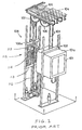
- FIG.3 is a diagrammatic view of the elevator showing a roping method of the present invention connecting the car and the counterweight by ropes outside of the projected horizontal area of the elevator car.
- FIG.4 is a diagrammatic view of FIG.3 showing the elevator car and counterweight in relation to the entire hoistway.
- a conventional elevator having an elevator car 101, a counterweight 112, a plurality of ropes 103, and a number of sheaves 106, 107, all located in a hoistway 110.
- the elevator car 101 has a ceiling 101a and a support frame 102 attached to that ceiling 101a.
- the counterweight 112 consists of a frame 113, weights 114, and the primary 108a of a linear motor 108.
- the linear motor 108 comprises the aforementioned movable primary 108a and a secondary 116 consisting of a ferromagnetic cylindrical column received by the primary 108a.
- the column 116 extends the length of the hoistway 110 and is attached to the hoistway 110 at the top 109 and the bottom 117 of the hoistway 110. Attractive and repulsive forces between the primary 108a and secondary 116 power the counterweight 112, and therefore the attached elevator car 101, up and down the hoistway 110.
- each rope 103 is attached to the support frame 102 attached to the ceiling 101a of the car 101. From there the ropes 103 extend up the hoistway 110 to the sheaves 106, 107. The sheaves 106,107 are attached to overhead beams 105 located directly above the car 101 at the top 109 of the hoistway 110. The ropes 103 wrap around the sheaves 106, 107 and return back down the hoistway 110, finally attaching to the counterweight 112.
- a minimum space 118 is required between the support frame 102 and the overhead beams 105 for safety purposes. Space 120 is also required between the ceiling 101a of the car 101 and the top of the support frame 102 attached to the car 101. This space 120 contributes to the unusable space in the hoistway 110.
- An elevator using this type of conventional arrangement has, therefore, a minimum of unusable space equal to the code required space 118 plus the space 120 from the ceiling 101a of the car 101 to the top of the support beam 102.
- an elevator having a car 1, a counterweight 25, a pair of ropes 6a, 6b, a pair of first sheaves 10, 12, a pair of second sheaves 11, 13, and a pair of third sheaves 14, 15.
- the car 1 has a ceiling 1b whose horizontal area is defined by a width 26 and a depth 27.
- a support frame 4 is attached to the ceiling 1b of the car 1 and a suspending frame 5 is attached to the floor of the car 1.
- the suspending frame 5 has extensions 5a projecting beyond the left and right sides of the car 1, passing through the center of gravity of the car 1.
- the counterweight 25 consists of a frame 28, weights 20, and the primary 17 of a linear motor 16.
- the linear motor 16 comprises the aforementioned movable primary 17 and a secondary 18 consisting of a ferromagnetic cylindrical column received by the primary 17.
- the column extends the length of the hoistway 2 and is attached to the hoistway 2 at the top 21 and the bottom 29 of the hoistway 2.
- the weight of the counterweight 25, including the primary 17, is set to equal the combined weight of the car 1 and the half of the weight of the rated maximum load of the elevator.
- the first 10, 12, second 11, 13, and third 14, 15 pairs of sheaves are cylindrical sheaves rotatably counted on axles 30.
- Each axle 30 is received and supported by a sheave bracket 31 having an arm on each side of the sheave.
- Each sheave bracket 31 is attached to and supported by a pair of spaced apart structural beams 8, 8a.
- One rope 6a is attached to an extension 5a of the suspending frame 5 projecting horizontally outward from the floor of the car on the left side of the car 1, and the other rope 6b is attached to an extension 5a of the suspending frame projecting horizontally outward from the floor of the car 1 on the right side.
- Each first sheave 10, 12 is mounted on a pair of spaced apart parallel structural beams 8, 8a at the top of the hoistway 2.
- the ropes 6a, 6b extending directly up from the extensions 5a, pass between the beams 8, 8a and enter the first sheaves 10, 12 centered on the beams 8, 8a.
- the ropes 6a, 6b are attached to the extensions 5a far enough away from the car 1 such that neither the beams 8, 8a nor the sheaves 10, 12 are located in the projected horizontal area 32 of the car 1.
- the projected horizontal area 32 of the car 1 is defined by the width 26 and the depth 27 of the car protected directly upward in the hoistway 2.
- Each rope 6a, 6b then wraps around the respective first sheave 10, 12 and passes back down between the structural beams 8, 8a to the second sheave 11, 13.
- the second sheaves 11, 13 are supported and centered on the same structural beams 8, 8a as the first sheaves 10, 12, but are located on the side opposite the first sheaves 10, 12.
- Each rope 6a, 6b wraps around the respective second sheave 11, 13 and exits passing upward back between the parallel, spaced apart structural beams 8, 8a, and is received by a third sheave 14, 15.
- the third sheaves are supported by a pair of parallel, spaced apart structural beams 34, 34a attached to the top of the structural beams 8, 8a supporting the first 10, 12 and second 11, 13 sheaves. Like the first 10, 12 and second 11, 13 sheaves, the third sheaves 14 15 and beams 34, 34a are positioned outside of the projected horizontal area 32 of the car 1.
- the ropes 6a, 6b wrap around the third sheaves 14, 15, exiting the third sheaves 14, 15 directly above the counterweight 25. The ropes 6a, 6b then attach to the counterweight 25, thereby fixing the counterweight 25 and the car 1 to one another.
- a single rope may be used to connect the elevator car 1 and the counterweight 25.
- the rope would attach to one side of the car 1 and extend upward to the sheave(s) on that side of the car. From there, the rope would either engage other sheaves and extend down to a sheave attached to the counterweight 25, or extend directly down to a sheave attached to the counterweight 25. The rope would then extend back up to the sheave(s) on the opposite side of the car 1 and return back to the car 1 along a path similar to that taken on the first side. In this case two portions of the single rope would follow the paths of the separate ropes 6a, 6b.
- the roping arrangement described heretofore saves space in two significant ways.
- the rope portions 6a, 6b are attached to the suspending frame 5 below the car 1. As a result, the unusable space between the ceiling 1b of the car 1 and the support frame 102 (see FIGS. 1 and 2) beam is eliminated.
Landscapes
- Engineering & Computer Science (AREA)
- Civil Engineering (AREA)
- Mechanical Engineering (AREA)
- Structural Engineering (AREA)
- Lift-Guide Devices, And Elevator Ropes And Cables (AREA)
- Types And Forms Of Lifts (AREA)
- Cage And Drive Apparatuses For Elevators (AREA)
Applications Claiming Priority (2)
| Application Number | Priority Date | Filing Date | Title |
|---|---|---|---|
| JP1991087670U JP2549837Y2 (ja) | 1991-10-25 | 1991-10-25 | エレベーターのかご吊り構造 |
| JP87670/91 | 1991-10-25 |
Publications (3)
| Publication Number | Publication Date |
|---|---|
| EP0539238A2 true EP0539238A2 (de) | 1993-04-28 |
| EP0539238A3 EP0539238A3 (en) | 1993-06-09 |
| EP0539238B1 EP0539238B1 (de) | 1995-12-27 |
Family
ID=13921385
Family Applications (1)
| Application Number | Title | Priority Date | Filing Date |
|---|---|---|---|
| EP19920309787 Expired - Lifetime EP0539238B1 (de) | 1991-10-25 | 1992-10-26 | Seilanordnungsverfahren eines Aufzugs |
Country Status (3)
| Country | Link |
|---|---|
| EP (1) | EP0539238B1 (de) |
| JP (1) | JP2549837Y2 (de) |
| DE (1) | DE69207148T2 (de) |
Cited By (6)
| Publication number | Priority date | Publication date | Assignee | Title |
|---|---|---|---|---|
| EP0849209A1 (de) * | 1996-12-20 | 1998-06-24 | Otis Elevator Company | Anbau eines Aufzugsantriebsgeräts |
| WO1999048791A1 (en) * | 1998-03-24 | 1999-09-30 | Eastern Elevators Pty. Limited | Elevator system |
| EP0953538A2 (de) * | 1998-04-28 | 1999-11-03 | Kabushiki Kaisha Toshiba | Gezogener Aufzug |
| JPH11310372A (ja) * | 1998-04-28 | 1999-11-09 | Toshiba Elevator Co Ltd | エレベータ装置 |
| AU736244B2 (en) * | 1998-03-24 | 2001-07-26 | Eastern Elevators Pty Limited | Elevator system |
| SG134994A1 (en) * | 2002-10-29 | 2007-09-28 | Inventio Ag | Lift counterweight |
Families Citing this family (2)
| Publication number | Priority date | Publication date | Assignee | Title |
|---|---|---|---|---|
| JP4849712B2 (ja) * | 2000-11-08 | 2012-01-11 | 東芝エレベータ株式会社 | エレベータ |
| KR100780499B1 (ko) * | 2005-05-26 | 2007-11-29 | 오티스 엘리베이터 컴파니 | 기계실이 없는 엘리베이터 시스템 |
Citations (4)
| Publication number | Priority date | Publication date | Assignee | Title |
|---|---|---|---|---|
| GB1054349A (de) * | 1900-01-01 | |||
| GB783408A (en) * | 1955-06-12 | 1957-09-25 | Anglo Amer Corp South Africa | Improvements in lifting, lowering and hauling and especially in mine hoisting |
| EP0402148A1 (de) * | 1989-06-08 | 1990-12-12 | Otis Elevator Company | Seilscheibenanordnung eines selbstangetriebenen Aufzugs mit Anwendung eines Linearmotors auf dem Gegengewicht |
| EP0410085A2 (de) * | 1989-07-11 | 1991-01-30 | Gerhard Schlosser | Antriebvorrichtung eines Aufzuges |
Family Cites Families (1)
| Publication number | Priority date | Publication date | Assignee | Title |
|---|---|---|---|---|
| JPH02233492A (ja) * | 1989-02-28 | 1990-09-17 | Otis Elevator Co | エレベータのかごの横吊り構造 |
-
1991
- 1991-10-25 JP JP1991087670U patent/JP2549837Y2/ja not_active Expired - Lifetime
-
1992
- 1992-10-26 DE DE1992607148 patent/DE69207148T2/de not_active Expired - Fee Related
- 1992-10-26 EP EP19920309787 patent/EP0539238B1/de not_active Expired - Lifetime
Patent Citations (4)
| Publication number | Priority date | Publication date | Assignee | Title |
|---|---|---|---|---|
| GB1054349A (de) * | 1900-01-01 | |||
| GB783408A (en) * | 1955-06-12 | 1957-09-25 | Anglo Amer Corp South Africa | Improvements in lifting, lowering and hauling and especially in mine hoisting |
| EP0402148A1 (de) * | 1989-06-08 | 1990-12-12 | Otis Elevator Company | Seilscheibenanordnung eines selbstangetriebenen Aufzugs mit Anwendung eines Linearmotors auf dem Gegengewicht |
| EP0410085A2 (de) * | 1989-07-11 | 1991-01-30 | Gerhard Schlosser | Antriebvorrichtung eines Aufzuges |
Cited By (12)
| Publication number | Priority date | Publication date | Assignee | Title |
|---|---|---|---|---|
| EP0849209A1 (de) * | 1996-12-20 | 1998-06-24 | Otis Elevator Company | Anbau eines Aufzugsantriebsgeräts |
| US5899300A (en) * | 1996-12-20 | 1999-05-04 | Otis Elevator Company | Mounting for an elevator traction machine |
| EP1547959A3 (de) * | 1996-12-20 | 2008-05-28 | Otis Elevator Company | Anbau für Aufzugsantriebsgerät |
| WO1999048791A1 (en) * | 1998-03-24 | 1999-09-30 | Eastern Elevators Pty. Limited | Elevator system |
| AU736244B2 (en) * | 1998-03-24 | 2001-07-26 | Eastern Elevators Pty Limited | Elevator system |
| EP0953538A2 (de) * | 1998-04-28 | 1999-11-03 | Kabushiki Kaisha Toshiba | Gezogener Aufzug |
| JPH11310372A (ja) * | 1998-04-28 | 1999-11-09 | Toshiba Elevator Co Ltd | エレベータ装置 |
| EP0953538A3 (de) * | 1998-04-28 | 2001-01-03 | Kabushiki Kaisha Toshiba | Gezogener Aufzug |
| US6382360B2 (en) | 1998-04-28 | 2002-05-07 | Kabushiki Kaisha Toshiba | Traction type elevator apparatus |
| US6390243B2 (en) | 1998-04-28 | 2002-05-21 | Kabushiki Kaisha Toshiba | Traction type elevator apparatus |
| US6491136B2 (en) | 1998-04-28 | 2002-12-10 | Kabushiki Kaisha Toshiba | Traction type elevator apparatus |
| SG134994A1 (en) * | 2002-10-29 | 2007-09-28 | Inventio Ag | Lift counterweight |
Also Published As
| Publication number | Publication date |
|---|---|
| JP2549837Y2 (ja) | 1997-10-08 |
| DE69207148T2 (de) | 1996-08-29 |
| JPH0537853U (ja) | 1993-05-21 |
| DE69207148D1 (de) | 1996-02-08 |
| EP0539238A3 (en) | 1993-06-09 |
| EP0539238B1 (de) | 1995-12-27 |
Similar Documents
| Publication | Publication Date | Title |
|---|---|---|
| KR100853662B1 (ko) | 견인 로프풀리 엘리베이터 | |
| EP0953538B1 (de) | Gezogener Aufzug | |
| JP3252575B2 (ja) | エレベータ装置 | |
| EP1471026B1 (de) | Aufzugsvorrichtung | |
| CN1105336A (zh) | 驱动装置下置的牵引绳轮式电梯 | |
| CN107539858B (zh) | 电梯 | |
| US5226507A (en) | Roping method of an elevator | |
| EP1364905B1 (de) | Träger für Aufzugskabine | |
| EP1302430B1 (de) | Aufzugsvorrichtung | |
| JP4140651B2 (ja) | エレベータ装置 | |
| EP0539238B1 (de) | Seilanordnungsverfahren eines Aufzugs | |
| JP3420811B2 (ja) | リニアモータ式エレベーター | |
| JPH11106159A (ja) | エレベーター | |
| JP4255525B2 (ja) | エレベーター | |
| US4529062A (en) | Elevator system | |
| EP2390219A1 (de) | Aufzugsvorrichtung | |
| US20110315487A1 (en) | Arrangement of elevator machines | |
| EP1535875B1 (de) | Aufzugsvorrichtung | |
| JPWO2018198232A1 (ja) | エレベータ装置 | |
| EP0385277A2 (de) | Laterale Hängestruktur für eine Aufzugskabine | |
| JP3148436B2 (ja) | エレベータの制動装置 | |
| JPH07144848A (ja) | リニアモータの固定子支持装置 | |
| JPH08231153A (ja) | エレベータ | |
| JP2862469B2 (ja) | リニアモータの固定子支持装置 | |
| JPH0791013B2 (ja) | エレベータ用釣合装置 |
Legal Events
| Date | Code | Title | Description |
|---|---|---|---|
| PUAI | Public reference made under article 153(3) epc to a published international application that has entered the european phase |
Free format text: ORIGINAL CODE: 0009012 |
|
| PUAL | Search report despatched |
Free format text: ORIGINAL CODE: 0009013 |
|
| AK | Designated contracting states |
Kind code of ref document: A2 Designated state(s): DE FR GB |
|
| AK | Designated contracting states |
Kind code of ref document: A3 Designated state(s): DE FR GB |
|
| 17P | Request for examination filed |
Effective date: 19931130 |
|
| 17Q | First examination report despatched |
Effective date: 19950126 |
|
| GRAA | (expected) grant |
Free format text: ORIGINAL CODE: 0009210 |
|
| AK | Designated contracting states |
Kind code of ref document: B1 Designated state(s): DE FR GB |
|
| REF | Corresponds to: |
Ref document number: 69207148 Country of ref document: DE Date of ref document: 19960208 |
|
| ET | Fr: translation filed | ||
| PLBE | No opposition filed within time limit |
Free format text: ORIGINAL CODE: 0009261 |
|
| STAA | Information on the status of an ep patent application or granted ep patent |
Free format text: STATUS: NO OPPOSITION FILED WITHIN TIME LIMIT |
|
| 26N | No opposition filed | ||
| ITF | It: translation for a ep patent filed |
Owner name: DATA SOLLECITO LETT. INC.:09/02/98;DE DOMINICIS & |
|
| PGFP | Annual fee paid to national office [announced via postgrant information from national office to epo] |
Ref country code: FR Payment date: 19980911 Year of fee payment: 7 |
|
| PGFP | Annual fee paid to national office [announced via postgrant information from national office to epo] |
Ref country code: GB Payment date: 19980917 Year of fee payment: 7 |
|
| PGFP | Annual fee paid to national office [announced via postgrant information from national office to epo] |
Ref country code: DE Payment date: 19980925 Year of fee payment: 7 |
|
| PG25 | Lapsed in a contracting state [announced via postgrant information from national office to epo] |
Ref country code: GB Free format text: LAPSE BECAUSE OF NON-PAYMENT OF DUE FEES Effective date: 19991026 |
|
| GBPC | Gb: european patent ceased through non-payment of renewal fee |
Effective date: 19991026 |
|
| PG25 | Lapsed in a contracting state [announced via postgrant information from national office to epo] |
Ref country code: FR Free format text: LAPSE BECAUSE OF NON-PAYMENT OF DUE FEES Effective date: 20000630 |
|
| PG25 | Lapsed in a contracting state [announced via postgrant information from national office to epo] |
Ref country code: DE Free format text: LAPSE BECAUSE OF NON-PAYMENT OF DUE FEES Effective date: 20000801 |
|
| REG | Reference to a national code |
Ref country code: FR Ref legal event code: ST |