EP0538963B1 - Krüger-Klappe mit drei Stellungen und variabeler Wölbung - Google Patents
Krüger-Klappe mit drei Stellungen und variabeler Wölbung Download PDFInfo
- Publication number
- EP0538963B1 EP0538963B1 EP92203280A EP92203280A EP0538963B1 EP 0538963 B1 EP0538963 B1 EP 0538963B1 EP 92203280 A EP92203280 A EP 92203280A EP 92203280 A EP92203280 A EP 92203280A EP 0538963 B1 EP0538963 B1 EP 0538963B1
- Authority
- EP
- European Patent Office
- Prior art keywords
- flap
- link
- panel
- trailing edge
- leading edge
- Prior art date
- Legal status (The legal status is an assumption and is not a legal conclusion. Google has not performed a legal analysis and makes no representation as to the accuracy of the status listed.)
- Expired - Lifetime
Links
Images


Classifications
-
- B—PERFORMING OPERATIONS; TRANSPORTING
- B64—AIRCRAFT; AVIATION; COSMONAUTICS
- B64C—AEROPLANES; HELICOPTERS
- B64C3/00—Wings
- B64C3/38—Adjustment of complete wings or parts thereof
- B64C3/44—Varying camber
- B64C3/48—Varying camber by relatively-movable parts of wing structures
-
- B—PERFORMING OPERATIONS; TRANSPORTING
- B64—AIRCRAFT; AVIATION; COSMONAUTICS
- B64C—AEROPLANES; HELICOPTERS
- B64C9/00—Adjustable control surfaces or members, e.g. rudders
- B64C9/14—Adjustable control surfaces or members, e.g. rudders forming slots
- B64C9/22—Adjustable control surfaces or members, e.g. rudders forming slots at the front of the wing
Definitions
- the present invention relates to a linkage mechanism as described in the pre-characterizing portion of claim 1 for extending a high lift leading edge flap mounted on the wing of an aircraft. More particularly the invention relates to a linkage mechanims for a variable camber Krueger leading edge flap having a first, stowed position for high speed cruise operation, a second, forwardly extending position in which the forward edge of the flap forms an aerodynamic slot with the leading edge of the wing for aircraft landing, and a third, also forwardly extending position in which the aerodynamic slot is sealed, and the flap angle of deflection decreased, for aircraft take-off.
- a linkage mechanism having all the features of the pre-characterizing portion of claim 1 is known from US-A-4 262 868 (Dean).
- Leading edge flaps such as variable camber Krueger (VCK) flap systems
- VCL variable camber Krueger
- VK flap systems are an attractive means of low speed stall protection on modern aircraft due to their relative simplicity and low weight.
- the flap In order to meet the specific aerodynamic requirements of new high speed wing designs which have evolved in recent years, it is necessary that the flap produce good lift coefficients for both landing and take-off operations.
- the leading edge flap system must provide (a) high lift coefficients with minimum drag for take-off, (b) the highest possible lift coefficient for the slowest possible landing, and (c) a small radius leading edge and minimum drag for efficient cruise.
- VCK-type leading edge flap system For a VCK-type leading edge flap system to provide these characteristics, it must (a) be configured with sealed, or near sealed, trailing edges for take-off, (b) be configured to provide a sufficiently large trailing edge slot for landing, and (c) be stowed with a sufficiently small radius leading edge for cruise.
- VCK flap systems and other devices have been proposed for changing the camber of an airfoil to improve low speed handling, while preserving suitable cruise characteristics.
- a VCK leading edge flap has been incorporated in the Boeing 747-type airplane, and a number of flaps of this and similar types are shown in the patent literature, examples of these being given below.
- U.S. Patent No. 4 262 868 shows a VCK flap which has the three operating positions discussed above.
- This device utilizes a three-point support for the variable camber flap surface:
- the trailing edge of the flap is supported off the wing by a small bell crank 33 which is connected to a chordwise extending beam 24; the rearward end of this beam is connected to the rear edge of the flap panel and the forward end is pivotally connected to the leading edge.
- the middle portion of the panel is supported from the central portion of the beam by a linkage.
- the beam is connected to the lower arm of a drive crank, the upper arm of which is connected to the support bell crank mentioned above.
- the drive crank extends the flap forwardly, and as this is done, links 16c and 37 push the middle portion of the flap panel outwardly to give it more camber.
- a separate bullnose 12 also rotates into position against the leading edge of the flap panel for take-off and landing.
- the Dean system may be suitable for many applications, it exhibits drawbacks in terms of cost, weight and efficiency.
- the device employs only a relatively simple pivoting motion (primarily about points 34, 17, and 15) to move between its deployed positions, it is not possible for it to provide the ideal positioning and angular orientation of the flap in each of these locations: in the landing position the panel should be relatively steeply angled to the airflow and have its trailing edge positioned forward of the leading edge of the wing to form the aerodynamic slot, while in the take-off position the panel should be more shallowly angled and have its trailing edge moved more or less directly rearwardly to the leading edge of the wing to form the aerodynamic seal.
- the Dean linkage cannot provide the motions necessary to do this, and so the flap's actual location and angulation in these positions represents a less than ideal compromise.
- the Dean system utilizes three separate supports along the flap panel, as well as an additional support for the separate bullnose, and each of these is expensive to fabricate and adds weight.
- the bullnose piece is separate from the flap panel, an aerodynamically inefficient discontinuity is created between these during deployment.
- the support bell crank 33 is positioned quite close to the leading edge of the wing, this interferes with the normal installation of anti-icing ducting in this area.
- U.S. Patent No. 3,743,219 shows another 3-position VCK flap system.
- the rear edge of the flap panel is connected directly by a link 64 to a bell crank 60 ⁇ , link 64 being suspended from the wing by a rocker arm 74.
- a pair of links connected to the other arm of the bell crank form a scissors arrangement which foreshortens the distance between the leading and trailing edges of the flap so as to bow the flap outwardly to the desired camber.
- the skin thickness of the flap is tapered, and this determines the proper amount of camber when flexed and also the position at which the greatest amount of camber occurs.
- U.S. Patent No. 3,50 ⁇ 4,870 ⁇ shows another VCK flap system having a stowed position under the wing and a high lift landing position in which a slot is formed with the leading edge of the wing.
- this device does not have the third position in which the trailing edge of the flap forms a seal with the wing for take-off.
- the linkage utilizes three separate support locations along the flap panel, and a separate bullnose piece, and so shares disadvantages with the Dean system.
- the rear edge of the flap panel is connected to a link 24 which is moved forwardly and rearwardly by the middle portion of a crank arm 16.
- the lower end of the crank arm is connected to a link 28 which acts through another link 39 to rotate the bullnose, and this also acts through a link 32 to move the middle portion of the flap panel outwardly to increase its camber.
- U.S. Patent No. 3,941,334 (Cole '334) is directed to a variable camber airfoil where the camber of the leading edge can be changed to increase or decrease lift. This incorporates a flap assembly which is generally similar to that shown by Cole et al. '870 ⁇ .
- U.S. Patent No. 3,90 ⁇ 4,451 (Cole '451) discloses essentially the same apparatus as Cole '334.
- U.S. Patent No. 3,910 ⁇ ,530 ⁇ shows another leading edge flap which is moved between stowed and deployed positions by means of a linkage having an arm 56 which is actuated by bell crank.
- the arm 56 At an intermediate pivot location 60 ⁇ , the arm 56 has a direct connection to the flap, by which it moves the flap to and from its deployed position.
- An outer pivot connection 88 of arm 56 acts through a link 86 to deploy a separate bullnose.
- U.S. Patent No. 3,556,439 shows a triple flap leading edge device which has two pivoting portions (leading edge flaps 19, 20 ⁇ ), plus a bullnose 21.
- leading edge flaps 19, 20 ⁇ both of the flap sections are rotated outwardly, with the forward of these extending forward of the other to form a slot.
- the take-off configuration one section rotates outwardly to the deployed position, and the other remains stowed within this.
- U.S. Patent No. 4,189,120 ⁇ shows a variable camber leading edge flap which is deployed by means of two links 30 ⁇ and 36, this being similar in overall configuration to that shown in Cole et al. '870 ⁇ .
- U.S. Patent No. 4,189,121 shows what is called a "variable twist leading edge flap".
- the flap extends downwardly and forwardly to its deployed position, and there is linkage which deploys a separate bullnose.
- U.S. Patent 4,351,50 ⁇ 2 shows a variable camber leading edge device for an airfoil, and does not involve a separately deployable flap.
- U.S. Patent No. 3,917,192 shows a mechanism having two separate flap members that deploy to form a double slotted arrangement.
- German Patent No. 2,10 ⁇ 1,536 shows a scissors type linkage which deploys a leading edge flap, this apparently being stowed against the outward surface of the wing for cruise.
- the present invention seeks to solve the problems cited above.
- this is accomplished by providing a linkage mechanism for extending a flap from a stowed position within the undersurface of an airfoil to a forward extended operative position, said linkage mechanism comprising:
- FIGS. 1-3 It is believed that a clearer understanding of the present invention will be obtained by first making reference to FIGS. 1-3, and describing with respect thereto the operation of the main aerodynamic components of the flap apparatus. After that, reference will be made to the remaining figures of the drawings, and the operating linkage and the remainder of the present invention will be described in more detail.
- FIGS. 1-3 show the outline of the forward portion of an airfoil, which in this embodiment is a main wing 10 ⁇ of an airplane.
- This wing 10 ⁇ has an upper surface 12, a lower surface 14, and a leading edge 16.
- the flap assembly of the present invention is generally designated 18, and for purposes of clarity, only a portion of flap assembly is illustrated in FIGS. 1-3.
- the two main aerodynamic components of flap assembly 18 are a flexible flap panel 20 ⁇ and a bullnose member 22.
- the panel 20 ⁇ has a trailing edge 24, and a leading edge 26 at which the bullnose member 22 is hinge connected.
- this flap assembly is deployed to three discreet positions, and the linkage and actuating mechanisms for doing this will be described later herein.
- the flap assembly 18 is shown in its stowed condition.
- the flap panel 20 ⁇ is positioned immediately rearwardly of the leading edge 16 of the wing, and is aerodynamically aligned with a lower surface portion 28 thereof, and is also aligned with the main aerodynamic lower surface 14 of the wing 10 ⁇ .
- the panel 20 ⁇ In this stowed position, the panel 20 ⁇ is substantially planar, with very little, if any, curvature.
- the flap assembly 18 travels from this stowed position downwardly and forwardly, and the camber (i.e., the curvature) of the flexible flap panel 20 ⁇ changes; also, the bullnose 22 begins to rotate about the hinge connection 26 towards its deployed position.
- FIG. 2 shows the flap assembly 18 positioned in its first high-lift position, this being for use during landing operations, where the panel 20 ⁇ has been flexed into a cambered configuration.
- the hinged bullnose member 22 extends downwardly from the front surface of panel 20 ⁇ and is aerodynamically aligned therewith in an optimized configuration.
- the flap panel assembly 18 In this first deployed position, the flap panel assembly 18 is positioned in a relatively steeply angled orientation relative to the airflow, and also, the trailing edge 24 of the panel section 20 ⁇ is positioned a moderate, but significant, distance forwardly from the leading edge 16 of the wing so as to define a slot 29.
- this slot 29 is crucial in increasing the lift generated by the wing of the airplane during low speed landing operations.
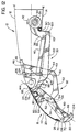
- FIG. 3 shows the flap assembly 18 having been moved to its second deployed position, this being an optimized configuration for use during take-off operations.
- the trailing edge 24 of the panel 20 ⁇ has been moved rearwardly so as to be positioned against a forward portion of the main airfoil 10 ⁇ , just above the leading edge 16, which eliminates slot 29 and forms an aerodynamic seal with the fixed wing structure.
- the camber of the panel 20 ⁇ and the position of the bullnose member 22 relative to panel 20 ⁇ may remain little changed from the landing configuration shown in FIG. 2, the flap itself is positioned in a somewhat shallower angular orientation relative to the airflow, so as to provide an optimized, low drag configuration for take-off.
- FIGS. 4-7 show the first of two linkage subassemblies which make up linkage assembly 30 ⁇ . More specifically, FIGS. 4-7 show only the first linkage subassembly 32 which, in addition to supporting the middle portion of the flap assembly as it is moved outwardly and forwardly from its stowed position, is primarily responsible for controlling the camber of the flap panel 20 ⁇ and the rotational movement of the bullnose 22 as flap assembly 18 moves between its various positions.
- the second sub-linkage making up linkage assembly 30 ⁇ will be described with reference to FIG. 8-11.
- FIG. 4 shows flap assembly 18 in its stowed position, with the flexible flap panel 20 ⁇ being in its generally planar configuration and aligned so as to form a substantially continuous aerodynamic surface with the lower surface 14 of wing 10 ⁇ . Because the linkage members are contracted to their most compact arrangement in order to be stowed within the airfoil, it is difficult to pick out the individual components of linkage subassembly 32 in FIG. 4, and so it is suggested that the reader view FIG. 5, which shows the main components more clearly.
- FIG. 5 shows flap assembly 18 partially extended from the stowed position to its first deployed position.
- Power is supplied to the linkage 30 ⁇ by a rotatably mounted drive shaft 34 which extends in a spanwise direction, this having a torque sleeve 35 mounted thereto.
- First and second parallel drive arms 36, 36' (36 only being shown in FIGS. 4-7) extend generally radially from torque sleeve 35.
- Each of these drive arms 36, 36' is attached to a mirror-image identical half of linkage 30 ⁇ , so, for purposes of clarity, only the half which is connected to drive arm 36 (which is pictured nearer the viewer) will be described herein with reference to FIGS. 4-12.
- Drive arm 36 has a Y-shaped outer end 37; a first pivot connection 38 on the rearward lobe is connected to the rearward end of an upper connecting link 40 ⁇ , the forward end of this being connected to pivot pin 42 at approximately the mid-length point of a first vertically extending support arm 44.
- This first support arm 44 has an upper end 45 which is connected, at upper pivot pin 46, to a fixed structure, such as a rib, in the forward portion of wing 10 ⁇ (a portion of this fixed structure being indicated at 48), so that support arm 44 can swing back and forth from this.
- the lower end 49 of support arm 44 is connected to the rearward end of a forwardly extending control link 52 at pivot pin 50 ⁇ .
- Control link 52 has several functions in the deployment of flap assembly 18. Firstly, control link 52 cooperates with the second linkage subassembly (not shown in FIGS. 4-7, but shown in FIGS. 8-11) to move the flap panel 20 ⁇ and the bullnose 22 to the deployed positions of FIGS. 2 and 3 (these positions also being shown in FIGS. 6 and 7). Secondly, it cooperates with other components of the first linkage subassembly to rotate the bullnose member 22 towards its deployed position (as shown in FIGS. 2 and 3). Thirdly, control link 52 cooperates with other components of first linkage subassembly 32 impose the proper camber on the flexible flap panel 20 ⁇ as this moves to its deployed position.
- control link 52 has three pivot pin connections.
- the first, at pivot pin 54, connects control link 52 to the middle portion of a chordwise extending, fixed-length flap panel control beam 56.
- the forward end of control link 52 is Y-shaped, and a second pivot pin 58 connects the forward lobe to one end of a bullnose deploying link 60 ⁇ .
- a third pivot pin connection 62 connects the other, rearward lobe to one end of an upper panel angular positioning link 64.
- the rotation of the forward end of control link 52 about pivot pin 54 operates links 60 ⁇ and 64, not only to rotate the bullnose member 22 to its deployed position, but also to effect two other motions to change the camber of the flexible panel 20 ⁇ .
- the forward end of the bullnose deploying link 60 ⁇ is pivotally connected to bullnose member 22 at pivot pin 66, this being positioned relatively near the leading edge of bullnose member 22, away from the hinge 70 ⁇ which joins the bullnose to the flap panel.
- a second pivot pin 72 is positioned closer to the hinge (i.e., in a chordwise position between pivot pin 66 and hinge 70 ⁇ ), and this connects the forward end of the fixed-length panel control beam 56 to the bullnose member.
- the other end of this beam is connected at pivot pin 74 to a rearward portion of an attachment fitting 76; this, in turn, is mounted to a spanwise extending beam 80 ⁇ which is mounted to the trailing edge portion of flexible flap panel 20 ⁇ .
- the bracket-like attachment fitting fits over beam 80 ⁇ , and has a forwardly projecting ear 82, at which the forward end of positioning link 64 is connected by pivot pin 84.
- FIG. 5 also shows a wedge-shaped sealing strip 86 on the inner surface of the flap panel 20 ⁇ , at the trailing edge thereof; this is received in a corresponding recess 88 in the lower surface portion 28 of the leading edge of the wing so as to form a seal therewith.
- a tubular sealing strip 90 ⁇ at the rear edge of the opening in surface 14, and this abuts the retracted bullnose member so as to form a seal.
- linkage subassembly 32 shown in FIGS. 4-7 is only a portion of the complete linkage assembly 30 ⁇ , and there is an additional linkage subassembly (which will be described with reference to FIG. 8-11) which cooperates in the proper deployment of the flap panel 20 ⁇ . More specifically, as will described later herein, this additional linkage shares the pivot connection 74 at the rearward end of the flap panel control beam 56, so that this additional linkage subassembly serves to properly locate the rearward portion of beam 56 and the trailing edge of flap panel 20 ⁇ during deployment.
- control link 52 acts as one part of a four-bar linkage which is made up of drive arm 36, connecting link 40 ⁇ , support arm 44, and control link 52: as drive shaft 34 and torque sleeve 35 are rotated in the direction indicated by arrow 92, this motion is transmitted through the four-bar linkage to the centrally located pivot pin 54 so as to drive the flap panel 20 ⁇ in an arc downwardly out of its stowed position and then forwardly towards its deployed positions.
- the second linkage subassembly controls the motion of the trailing edge portion of the flap panel so as to insure the correct positioning and angular alignment of the flap panel, as will be described below.
- control link 52 simultaneously performs its second function of rotating the bullnose member 22 to its properly deployed position.
- the Y-shaped forward end of control link 52 rotates on pin 54 relative to control beam 56: in the stowed position (FIG. 4), the pivot pin 58 connecting the forward lobe 98 to bullnose deploying link 60 ⁇ is rotated rearwardly to a position generally between pivot pin 54 and panel 20 ⁇ , so that the link 60 ⁇ which is connected thereto is also retracted rearwardly; then, the rotation of link 52 about pivot pin 54 during the deployment of the flap assembly drives the bullnose deploying link 60 ⁇ forwardly so that the bullnose member rotates outwardly about pivot pin 72 to its deployed positions (see FIGS. 6 and 7).
- a hinge connection 70 ⁇ may be a piano-type hinge, which provides a smooth, aerodynamically continuous joint between the outer surfaces of the bullnose member and the flap panel, and also provides the joint with enhanced stability in operation, although hinge 70 ⁇ may of course be some other suitable mechanical or elastomeric hinge or the like.
- control link 52 cooperates with other linkage components to impose the proper camber on panel 20 ⁇ .
- bullnose deploying link 60 ⁇ is driven forwardly in the manner previously described, so that the bullnose member pivots about pivot pin 72, the leading edge 10 ⁇ 4 of the bullnose moves generally forwardly while the trailing edge 10 ⁇ 6 moves generally rearwardly.
- This rearward motion of the trailing edge of the bullnose displaces the leading edge of the flap panel in a rearward direction; however, the trailing edge portion 10 ⁇ 8 of the flap panel is fixedly mounted (via beam 80 ⁇ and attachment fitting 76) to the rearward end of fixed length beam 56.
- linkage subassembly 32 positively positions the trailing edge portion of the flap panel in angular alignment with the curved central portion. This is accomplished by means of positioning link 64, which, as was described above, is connected to the rearward lobe 10 ⁇ 0 ⁇ of the end of control link 52, the other end of link 64 being connected to the forwardly extending ear 82 of attachment fitting 76. At the beginning of deployment, lobe 10 ⁇ 0 ⁇ is rotated away from the inner surface of flap panel 20 ⁇ (see FIG. 5), so that link 64 is retracted or withdrawn away from panel 20 ⁇ .
- FIGS. 8-12 show the operation of the second linkage subassembly 118, and how this cooperates with the first linkage subassembly which has been described.
- a primary function of this second linkage subassembly is to properly position the trailing edge portion of flap assembly 18, thus insuring the proper angulation of the flap assembly as it is deployed.
- FIG. 9 which shows the main components more clearly than in the stowed position of FIG. 8.
- linkage subassembly 118 power is supplied to linkage subassembly 118 from drive shaft 34.
- the drive is taken from the forward lobe 119 of drive arm 36, this being connected by pivot pin 120 ⁇ to the rearward end of an upper support beam 122.
- Beam 122 is supported from the fixed structure 48 of wing 10 ⁇ an by upper support arm 124; the upper end of support arm 124 is connected to structure 48 by pivot pin 126, while the lower end of the support arm is connected to a middle portion of beam 122 by a second pivot pin 128.
- Beam 122 is consequently supported for forward and aft "swinging" movement as drive arm 36 is rotated by drive shaft 34.
- the forward end of beam 122 is connected to the rearward end of attachment fitting 76 by pivot pin 74, which it shares with the rearward end of the panel control beam 56.
- linkage subassembly 118 positions its rearward end at points about which the rest of flap panel assembly is pivoted to achieve the desired angular orientation. Because of the additional lever arm provided by support arm 44 in the first linkage subassembly 32, this moves the middle portion of flap assembly 18 (at pivot pin 54) forward a greater distance per a given amount of rotation of drive arm 36 than the distance by which pivot pin 74 is moved forward by second linkage subassembly 118. As a result, the forward and middle portions of flap assembly 18 pivot downwardly and then forwardly around pivot pin 74 as the assembly is deployed.
- FIG. 9 An important advantage of this arrangement is illustrated in FIG. 9.
- This shows flap assembly 18 during the initial stages of deployment, immediately after it has begun to move downwardly from the lower surface of wing 10 ⁇ . Because the flap assembly rotates downwardly and forwardly about pivot pin 74, at this point the leading edge 26 of flap panel 20 ⁇ (which is towards the rear of the wing in this position) has extended downwardly further than the trailing edge portion 10 ⁇ 8.
- the inclined aerodynamic surface 96 of the flap panel thus avoids the "scoop" effect which occurs in some prior art devices at this point in the deployment.
- the angulation of the flap panel which is shown in FIG. 9 tends to force the flap assembly 18 towards the stowed position, and so guards against accidental self-deployment of the assembly due to aerodynamic forces.
- Another, generally more significant advantage of using the two linkage subassemblies 32 and 118 described above is that this permits the assembly to use the simple rotational motion of driveshaft 34 to first position the flap in an ideal landing configuration, in which it is relatively steeply angled to the airflow and positioned relatively far forward of the fixed wing structure so as to form an aerodynamic slot therewith, and to then move the flap to a more shallowly angled orientation and rearwardly against the leading edge of the wing so as to form an aerodynamic seal therewith so as to achieve an ideal takeoff configuration.
- the system of the present invention utilizes one linkage subassembly to provide the primary downward and forward movement of the flap assembly while a different subassembly attends to the control of the trailing edge portion of the flap so as to provide the desired angulation and the final rearward movement into abutment with the leading edge of the wing.
- FIG. 12 shows panel assembly 18 in the shallowly angulated takeoff configuration, with its trailing edge forming the aerodynamic seal with the wing.
- the drive shaft 34 is rotated an additional amount in the directional indicated by arrow 92. This rotates the outer end of drive arm 36 past its most forwardly extended position, so that it begins to move rearwardly. As this is done, support beam 122 is drawn rearwardly, swinging movement in this direction being permitted by the pivoting upper support arm 124. Because beam 122 is connected to the leading lobe (in terms of direction of rotation) on drive arm 36, the rotation of drive shaft 34 from the position shown in FIG. 11 to the position shown in FIG.
- linkage system of the present invention overcomes the oversensitivity problems of some of the known systems discussed above. Because the motion of the flap assembly 18 from the first operative position shown in FIG. 11 to the second operative position shown in FIG. 12 results from the generally linear movements of the upper support beams of the second linkage subassembly, and the connecting and control links of the first linkage subassembly, this movement corresponds to a relatively greater amount of rotation of the drive shaft than is the case in several of the known systems discussed above (e.g., Cole '870 ⁇ , Dean), where this movement is more directly subtended by the rotation of a bell crank.
- drive shaft 34 rotates approximately 126 degrees from the stowed position to the first deployed position shown in FIG. 11, and then rotates an additional 36 degrees beyond this to the second deployed position shown in FIG. 12 (for a total of 162 degrees of rotation).
- This relatively large amount of rotation between each of the three distinct positions of the flap assembly renders it much easier to control the system accurately.
- FIG. 13 shows the various parallel links and other features of the first and second linkage subassemblies, all of which were not visible in the views of FIGS. 4-12. These include the first and second wing ribs 48, 48' (from which linkage 30 ⁇ is hung), the first and second parallel connecting links 40 ⁇ , 40 ⁇ ', and the parallel upper support beams 122, 122'. Also shown is the Y-shaped upper end of support arm 44, one fork of which is connected to the first rib 48 at pivot pin 46, and the second fork of which is connected to rib 48' at pivot pin 46'; the single lower end of support arm 44 is also shown, this being connected to control link 52 at pivot pin 50 ⁇ in the manner previously described.
- the arms 124, 124' which supports beam 122 are also shown hung off the parallel ribs 48, 48'; in this case, these arms are joined together at their upper ends to form an inverted "U” or horseshoe-shaped structure, which provides both greater strength and insures that these arms move in unison, and which also provides clearance for support arm 44 to pass between the lower ends of these two arms.
- the lower ends of support arms 124, 124' are forked to form clevises which are joined to beams 122, 122' by pivot pins 128, 128'.
- FIG. 13 also shows the configuration of attachment fitting 76: this has two upstanding wall portions 132, 132', which are spread apart from one another at the rearward end of the fitting for attachment to the forward ends of the two parallel beams 122, 122', and which then come close together at the forward end of the fitting for attachment to the single positioning link 64 at pivot pin 84. Also, the two parallel panel control beams 56, 56' are connected by pivot pins 74, 74' to the two spread apart wall portions at the rear of attachment fitting 76, and extend forwardly therefrom to pivot connections 72, 72' on bullnose member 22, this having a rearwardly extending mounting lug 134 which fits between two forward ends of the control beams.
- FIG. 14 shows flap panel 18 in a series of sequential positions 140 ⁇ a-140 ⁇ k, which represent the motion and orientation of the flap panel as it is deployed.
- the flap panel presents an aerodynamically continuous surface to the airstream (i.e., a surface which is generally free of discontinuities, as between the flap panel and the bullnose member), and this surface is also continuously angled so as to avoid any "scoop" effect which could cause accidental deployment of the assembly.
- the flap panel first pivots in a downward and then forward direction to the first deployed position, and then moves generally straight back to the second deployed position, in which it forms the seal with the leading edge of the wing (see esp. 140 ⁇ k-140 ⁇ l).
- Yet another advantage of the present invention is that it does not interfere with the installation of de-icing ducting 144 within the interior of the leading edge of the wing structure. This is because the linkage 30 relies on the somewhat linear, "swinging" motion of the support beams 122 and control link 52 for operation, and so it is impossible to hang the support arms 124 and 44 off the wing rib structure 48 relatively far back from the leading edge of the wing, thus leaving room for the de-icing duct.
Claims (8)
- Gestängemechanismus (30) zum Ausfahren einer Klappe (18) aus einer innerhalb der Unterfläche (14) einer Tragfläche (10) verstauten Position in eine vorwärts ausgefahrene operative Position, wobei der Gestängemechanismus (30) folgendes umfaßt:- eine erste Gestängeunteranordnung (32), umfassend:einen ersten Antriebsarmteil (36), der zur Drehung in einer sehnenweisen Ebene an der festen Struktur der Tragfläche (10) angebracht ist; undein erstes Antriebsglied (40), das ein rückwärtiges Ende (38) hat, welches an dem ersten Antriebsarmteil (36) angebracht ist, und ein vorderes Ende, das operativ mit einem mittleren Teil der Klappe (18) verbunden ist, so daß das Antriebsglied (40) in Ansprechung auf eine Drehung des Antriebsarmteils (36) die Klappe (18) nach abwärts und vorwärts in die operative Position ausfährt; und- eine zweite Gestängeunteranordnung (118), umfassend:dadurch gekennzeichnet, daß das vordere Ende (42) des ersten Antriebsglieds (40) drehbar an einem unteren Teil eines separaten Klappenhaltearms (44) angebracht ist, wobei ein oberes Ende (46) desselben direkt drehbar an der festen Struktur (48) der Tragfläche (10) angebracht ist, so daß es das erste Antriebsglied (40) zum Ausfahren relativ zu der Tragfläche (10) hält, und daß das zweite Antriebsglied (122) sein vorderes Ende (74) direkt drehbar mit dem Klappenhinterkantenteil (24) verbunden hat und den unteren Teil (128) des Hinterkantenhaltearms (124) drehbar daran an einem Ort zwischen seinem vorderen und rückwärtigen Ende (74, 120) angebracht hat, so daß er das zweite Antriebsglied (122) für das Ausfahren relativ zu der Tragfläche (10) hält.einen zweiten Antriebsarmteil (36), der zur Drehung koaxial mit dem ersten Antriebsarmteil (36) angebracht ist;ein zweites Antriebsglied (122), das ein rückwärtiges Ende (120) hat, welches an dem zweiten Antriebsarmteil (36) angebracht ist, und ein vorderes Ende (74), welches operativ mit einem Hinterkantenteil (24) der Klappe (18) verbunden ist, so daß das zweite Antriebsglied (122) in Ansprechung auf eine Drehung des zweiten Antriebsarmteils (36) den Hinterkantenteil (24) der Klappe (18) zu einer vorbestimmten Position in der operativen Position ausfährt; undeinen Hinterkantenhaltearm (124), der ein oberes Ende (126) hat, das drehbar an der festen Struktur (48) des Tragflügels (10) angebracht ist, und einen unteren Teil (128), der operativ mit dem Hinterkantenteil (24) der Klappe (18) so verbunden ist, daß er den Hinterkantenteil (24) der Klappe (18) zum Ausfahren relativ zu der Tragfläche (10) hält, wobei der Hinterkantenhaltearm (124) weiter drehbar mit dem zweiten Antriebsglied (122) verbunden ist,
- Gestängemechanismus (30) nach Anspruch 1, dadurch gekennzeichnet, daß die erste Gestängeunteranordnung (32) weiter folgendes umfaßt:- einen Endteil (49) des Klappenhaltearms (44), welcher sich von dem ersten Antriebsglied (40), das drehbar an dem Klappenhaltearm (44) angebracht ist, nach abwärts erstreckt; und- ein Verbindungsglied (52), das ein rückwärtiges Ende (50) hat, welches an dem Endteil (49) des Klappenhaltearms (44) angebracht ist, und ein vorderes Ende (54), das drehbar an dem mittleren Teil der Klappe (18) angebracht ist.
- Gestängemechanismus (30) nach Anspruch 2, gekennzeichnet durch:- ein erste Glied (60), das ein äußeres Ende (66) hat, welches mit einem Vorderkantenteil (26) eines flexiblen Felds bzw. einer flexiblen Platte (20) der Klappe (18) verbunden ist und sich davon nach rückwärts erstreckt;- ein zweites Glied (64), das ein äußeres Ende (84) hat, welches mit einem Hinterkantenteil (24) des flexiblen Felds bzw. der flexiblen Platte (20) verbunden ist und sich davon nach vorwärts erstreckt; undwobei ein inneres Ende (58) des ersten Glieds (60) und ein inneres Ende (62) des zweiten Glieds (64) zur Verkürzung des Abstands zwischen den äußeren Enden (66, 84) des ersten (60) und zweiten (64) Glieds operativ mit dem vorderen Ende (54) des Verbindungsglieds (52) verbunden sind, so daß die Wölbung der Klappe (18) erhöht wird, wenn das Klappenfeld bzw. die Klappenplatte (20) durch das Verbindungsglied (52) nach abwärts und vorwärts ausgefahren wird.
- Gestängemechanismus (30) nach Anspruch 3, gekennzeichnet durch:- ein Bullnasenteil (22), das drehbar an der Vorderkante (26) des flexiblen Felds bzw. der flexiblen Platte (20) der Klappe (18) zur sehnenweisen Drehung angebracht ist;- einen sich sehnenweise erstreckenden Träger (56) fester Länge, der ein vorderes Ende (72) hat, das drehbar an dem Bullnasenteil (22) benachbart der Vorderkante (26) des Felds bzw. der Platte (20) angebracht ist, sowie ein rückwärtiges Ende (74), das drehbar an dem Hinterkantenteil (24) des Felds bzw. der Platte (20) angebracht ist, und einen mittleren Teil, der drehbar an dem vorderen Ende (54) des Verbindungsglieds (52) angebracht ist; und- wobei das äußere Ende (66) des ersten Glieds (60) auf einer gegenüber der Vorderkante (26) des Felds bzw. der Platte (20) sehnenweise entgegengesetzten Seite des vorderen Endes (72) des Trägers (56) drehbar mit dem Bullnasenteil (22) verbunden ist, so daß das erste Glied (60), wenn sich das vordere Ende (54) des Verbindungsglieds (52) relativ zu dem Träger (56), wenn die Klappe (18) in die operative Position ausgefahren wird, verdreht, nach vorwärts ausgefahren wird, so daß sich das Bullnasenteil (22) um das vordere Ende (72) des Trägers (56) von fester Länge verdreht, so daß der Abstand zwischen der vorderen (26) und hinteren (24) Kante des flexiblen Felds bzw. der flexiblen Platte (20) verkürzt wird, so daß sich ein mittlerer Teil (110) des Felds bzw. der Platte (20) nach auswärts krümmt, so daß die Wölbung der Klappe (18) erhöht wird.
- Gestängemechanismus (30) nach Anspruch 4, dadurch gekennzeichnet, daß das äußere Ende (84) des zweiten Glieds (64) an dem Hinterkantenteil (24) des Felds bzw. der Platte (20) vorwärts von dem rückwärtigen Ende (74) des Trägers (56) fester Länge angebracht ist, so daß, wenn sich das vordere Ende (54) des Verbindungsglieds (52) relativ zu dem Träger (56) verdreht, wenn die Klappe (18) in die operative Position ausgefahren wird, das zweite Glied (64) nach auswärts ausgefahren wird, so daß sich der Hinterkantenteil (24) des flexiblen Felds bzw. der flexiblen Platte (20) um das rückwärtige Ende (74) des Trägers (56) von fester Länge verdreht, so daß der Hinterkantenteil (24) des Felds bzw. der Platte (20) mit dem auswärts gekrümmten mittleren Teil (110) des Felds bzw. der Platte (20) winkelmäßig zur Fluchtung gebracht bzw. ausgerichtet wird.
- Gestängemechanismus (30) nach Anspruch 4 oder 5, gekennzeichnet durch ein sich spannweitenweise erstreckendes Gelenk (70) vom Piano-Typ, welches das Bullnasenteil (22) mit der Vorderkante (26) des Felds bzw. der Platte (20) drehbar verbindet.
- Gestängemechanismus (30) nach irgendeinem der vorhergehenden Ansprüche, dadurch gekennzeichnet, daß das zweite Antriebsglied (122) so konfiguriert ist, daß das zweite Antriebsglied (122) in Ansprechung auf eine Drehung des zweiten Antriebsarmteils (36) in eine erste Winkelposition den Hinterkantenteil (24) der Klappe (18) an einem ersten vorbestimmten Ort derart positioniert, daß die Hinterkante (24) der Klappe (18) nach vorwärts von einer Vorderkante (16) der Tragfläche (10) beabstandet ist, so daß sie damit einen aerodynamischen Schlitz (29) bildet, und das zweite Antriebsglied (122) in Ansprechung auf eine Drehung des zweiten Antriebsarmteils (36) in eine zweite Winkelposition den Hinterkantenteil (24) der Klappe (18) nach rückwärts an einen zweiten vorbestimmten Ort zieht, derart, daß die Hinterkante (24) der Klappe (18) benachbart der Vorderkante (16) der Tragfläche (10) positioniert wird, so daß sie damit eine aerodynamische Abdichtung bildet.
- Tragfläche (10), die eine obere Oberfläche (12), eine untere Oberfläche (14), eine Vorderkante (16) und eine Klappenanordnung (18) hat, wobei die Klappenanordnung (18) durch den Gestängemechanismus (30) nach irgendeinem der vorhergehenden Ansprüche zur Entfaltung aus einer innerhalb der Unterfläche (14) der Tragfläche verstauten Position in eine erste vordere Betriebsposition, in welcher die Klappe (18) von der Vorderkante (16) beabstandet ist, und eine zweite vordere Betriebsposition, in welcher eine rückwärtige Kante der Klappe (18) aerodynamisch mit Bezug auf die Vorderkante (16) abgedichtet ist, an der Tragfläche (10) angebracht ist.
Applications Claiming Priority (2)
| Application Number | Priority Date | Filing Date | Title |
|---|---|---|---|
| US07/782,525 US5158252A (en) | 1991-10-24 | 1991-10-24 | Three-position variable camber Krueger leading edge flap |
| US782525 | 1991-10-24 |
Publications (2)
| Publication Number | Publication Date |
|---|---|
| EP0538963A1 EP0538963A1 (de) | 1993-04-28 |
| EP0538963B1 true EP0538963B1 (de) | 1997-03-26 |
Family
ID=25126322
Family Applications (1)
| Application Number | Title | Priority Date | Filing Date |
|---|---|---|---|
| EP92203280A Expired - Lifetime EP0538963B1 (de) | 1991-10-24 | 1992-10-23 | Krüger-Klappe mit drei Stellungen und variabeler Wölbung |
Country Status (3)
| Country | Link |
|---|---|
| US (1) | US5158252A (de) |
| EP (1) | EP0538963B1 (de) |
| DE (1) | DE69218545T2 (de) |
Cited By (3)
| Publication number | Priority date | Publication date | Assignee | Title |
|---|---|---|---|---|
| US7204454B2 (en) | 2005-02-25 | 2007-04-17 | Northrop Grumman Corporation | Aircraft with articulated leading edge of fuselage and wings |
| US7216835B2 (en) | 2005-02-25 | 2007-05-15 | Northrop Grumman Corporation | Aircraft with extendable leading edge of fuselage and wings |
| US7246770B2 (en) | 2005-02-25 | 2007-07-24 | Northrop Grumman Corporation | Aircraft with rotatable leading edge of fuselage and wings |
Families Citing this family (56)
| Publication number | Priority date | Publication date | Assignee | Title |
|---|---|---|---|---|
| FR2695905B1 (fr) * | 1992-09-24 | 1994-12-16 | Aerospatiale | Bec kruger rigide, pour bord d'attaque de voilure d'aéronef. |
| US5749546A (en) * | 1995-07-10 | 1998-05-12 | The Boeing Company | Method and apparatus for reducing airframe aerosound |
| US5681013A (en) * | 1995-12-26 | 1997-10-28 | The Boeing Company | Vortex leading edge flap assembly for supersonic airplanes |
| US5927656A (en) * | 1996-06-26 | 1999-07-27 | The Boeing Company | Wing leading edge flap and method therefor |
| EP0932548B1 (de) | 1996-10-22 | 2003-01-22 | The Boeing Company | Flugzeug mit ungepfeiltem schlitzflügel für den reiseflug |
| US5975466A (en) * | 1998-06-02 | 1999-11-02 | Northrop Grumman Corporation | Variable displacement fuel tank for aircraft |
| US6318070B1 (en) * | 2000-03-03 | 2001-11-20 | United Technologies Corporation | Variable area nozzle for gas turbine engines driven by shape memory alloy actuators |
| US6375126B1 (en) | 2000-11-16 | 2002-04-23 | The Boeing Company | Variable camber leading edge for an airfoil |
| EP1338506A1 (de) * | 2002-02-15 | 2003-08-27 | Fairchild Dornier GmbH | Flugzeugflügel mit Spalt- und Krüger-Klappen |
| US7258308B2 (en) | 2002-07-02 | 2007-08-21 | The Boeing Company | Method and apparatus for controlling airflow with a gapped trailing edge device having a flexible flow surface |
| US6796534B2 (en) | 2002-09-10 | 2004-09-28 | The Boeing Company | Method and apparatus for controlling airflow with a leading edge device having a flexible flow surface |
| KR100489739B1 (ko) * | 2002-12-05 | 2005-05-16 | 한국항공우주연구원 | 카나드-로터 날개용 양방향 에어포일 |
| US6892982B2 (en) * | 2003-01-29 | 2005-05-17 | Northrop Grumman Corporation | Aircraft with forward opening inlay spoilers for yaw control |
| US7059563B2 (en) | 2003-06-03 | 2006-06-13 | The Boeing Company | Systems, apparatuses, and methods for moving aircraft control surfaces |
| US6935592B2 (en) * | 2003-08-29 | 2005-08-30 | Supersonic Aerospace International, Llc | Aircraft lift device for low sonic boom |
| US6799739B1 (en) | 2003-11-24 | 2004-10-05 | The Boeing Company | Aircraft control surface drive system and associated methods |
| US7278610B2 (en) * | 2004-03-03 | 2007-10-09 | Goodrich Corporation | Aircraft wing with electrothermal deicing and/or anti-icing device |
| US6978971B1 (en) | 2004-06-15 | 2005-12-27 | The Boeing Company | Methods and apparatuses for controlling airflow proximate to engine/airfoil systems |
| US7270305B2 (en) * | 2004-06-15 | 2007-09-18 | The Boeing Company | Aircraft leading edge apparatuses and corresponding methods |
| US7494094B2 (en) | 2004-09-08 | 2009-02-24 | The Boeing Company | Aircraft wing systems for providing differential motion to deployable lift devices |
| US7264206B2 (en) | 2004-09-30 | 2007-09-04 | The Boeing Company | Leading edge flap apparatuses and associated methods |
| US7338018B2 (en) | 2005-02-04 | 2008-03-04 | The Boeing Company | Systems and methods for controlling aircraft flaps and spoilers |
| US7721999B2 (en) | 2005-05-20 | 2010-05-25 | The Boeing Company | Aerospace vehicle fairing systems and associated methods |
| DE102005031840B4 (de) * | 2005-07-06 | 2013-11-14 | Airbus Operations Gmbh | Antriebs- und Führungsvorrichtung für eine an einem Flugzeugtragflügel angeordnete Klappe |
| US7708231B2 (en) | 2005-11-21 | 2010-05-04 | The Boeing Company | Aircraft trailing edge devices, including devices having forwardly positioned hinge lines, and associated methods |
| US7475854B2 (en) | 2005-11-21 | 2009-01-13 | The Boeing Company | Aircraft trailing edge devices, including devices with non-parallel motion paths, and associated methods |
| GB0700604D0 (en) * | 2007-01-11 | 2007-02-21 | Airbus Uk Ltd | A leading edge structure for an aerofoil |
| GB0722425D0 (en) * | 2007-11-15 | 2007-12-27 | Airbus Uk Ltd | Slat support funk plate |
| US7954769B2 (en) | 2007-12-10 | 2011-06-07 | The Boeing Company | Deployable aerodynamic devices with reduced actuator loads, and related systems and methods |
| US7766282B2 (en) | 2007-12-11 | 2010-08-03 | The Boeing Company | Trailing edge device catchers and associated systems and methods |
| GB0805599D0 (en) * | 2008-03-28 | 2008-04-30 | Airbus Uk Ltd | Slat deployment mechanism |
| GB0810724D0 (en) | 2008-06-12 | 2008-07-16 | Airbus Uk Ltd | Slat assembly |
| US8226048B2 (en) | 2008-12-09 | 2012-07-24 | The Boeing Company | Link mechanisms, including Stephenson II link mechanisms for multi-position flaps and associated systems and methods |
| US8382045B2 (en) | 2009-07-21 | 2013-02-26 | The Boeing Company | Shape-changing control surface |
| DE102010014792A1 (de) * | 2010-04-13 | 2011-10-13 | Airbus Operations Gmbh | Hochauftriebssystem für ein Flugzeug |
| GB201018176D0 (en) | 2010-10-28 | 2010-12-08 | Airbus Operations Ltd | Krueger |
| DE102011014687A1 (de) * | 2011-03-22 | 2012-09-27 | Airbus Operations Gmbh | Lasteinleitungselement für eine bewegbare Fläche eines Flugzeugs, Flugzeug mit mindestens einer bewegbaren Fläche und mindestens einem Lasteinleitungselement und Verfahren zum Lösen einer mit einem Lasteinleitungselement verbundenen bewegbaren Fläche |
| DE102011018906A1 (de) * | 2011-04-28 | 2012-10-31 | Airbus Operations Gmbh | Hochauftriebssystem für ein Flugzeug und Verfahren zum Beeinflussen der Hochauftriebseigenschaften eines Flugzeugs |
| DE102011105912A1 (de) * | 2011-06-28 | 2013-01-03 | Airbus Operations Gmbh | Tragflügel mit einem Hauptflügel und einem Hochauftriebskörper sowie Verfahren zur Ausführung von Verstellbewegungen eines Hochauftriebskörpers gegenüber einem Hauptflügel |
| US8622350B1 (en) * | 2011-11-14 | 2014-01-07 | The Boeing Company | Compound leading edge device for aircraft |
| US9016637B2 (en) | 2012-02-10 | 2015-04-28 | The Boeing Company | High-positioned 3-position variable camber krueger |
| US9555871B2 (en) * | 2012-03-05 | 2017-01-31 | The Boeing Company | Two-surface sandwich structure for accommodating in-plane expansion of one of the surfaces relative to the opposing surface |
| US8925870B1 (en) | 2012-03-09 | 2015-01-06 | The Boeing Company | Morphing wing leading edge |
| US9365284B2 (en) | 2013-04-22 | 2016-06-14 | The Boeing Company | High-positioned 2-position variable camber Krueger |
| US9598167B2 (en) | 2014-03-04 | 2017-03-21 | The Boeing Company | Morphing airfoil leading edge |
| US9415856B2 (en) | 2014-06-04 | 2016-08-16 | The Boeing Company | Dual-rib morphing leading edge |
| ES2808671T3 (es) | 2016-04-11 | 2021-03-01 | Asco Ind Nv | Dispositivo hipersustentador |
| US11046419B2 (en) * | 2017-05-02 | 2021-06-29 | Airbus Operations Gmbh | Aerodynamic sealing and wing for an aircraft comprising such sealing |
| US10829198B2 (en) * | 2017-06-21 | 2020-11-10 | The Boeing Company | Krueger flap apparatus and methods incorporating a bullnose having a contour variation along a spanwise direction |
| US10207791B2 (en) * | 2017-06-23 | 2019-02-19 | The Boeing Company | Actuator assemblies to deploy aircraft leading edge flaps and seals for aircraft leading edge flaps |
| JP6929809B2 (ja) | 2018-03-02 | 2021-09-01 | 三菱重工業株式会社 | 高揚力装置、翼及び航空機 |
| US11192631B2 (en) * | 2018-06-19 | 2021-12-07 | Airbus Operations Gmbh | Connection assembly for transmitting loads between two wing elements |
| US11332233B2 (en) | 2018-07-16 | 2022-05-17 | Airbus Operations Gmbh | System for driving a flap arrangement between a retracted position and an extended position |
| CA3048431A1 (en) | 2019-07-03 | 2021-01-03 | Jaye Mangione | Deforming foil structure for bridging curved fluid-dynamic surface |
| US11377197B2 (en) * | 2019-07-10 | 2022-07-05 | The Boeing Company | High lift systems for aircraft and related methods |
| EP4063257A1 (de) * | 2021-03-23 | 2022-09-28 | Airbus Operations GmbH | Flügel für ein flugzeug |
Family Cites Families (12)
| Publication number | Priority date | Publication date | Assignee | Title |
|---|---|---|---|---|
| US3504870A (en) * | 1967-12-08 | 1970-04-07 | Boeing Co | Aircraft wing variable camber leading edge flap |
| US3556439A (en) * | 1968-11-22 | 1971-01-19 | Boeing Co | Methods and high lift systems for making an aircraft wing more efficient for takeoffs and landings |
| US3743219A (en) * | 1971-06-30 | 1973-07-03 | Boeing Co | High lift leading edge device |
| US3917192A (en) * | 1973-07-09 | 1975-11-04 | Alvarez Calderon Alberto | Flap mechanisms and apparatus |
| US3910530A (en) * | 1973-11-07 | 1975-10-07 | Boeing Co | Leading edge flap |
| US3994451A (en) * | 1974-03-28 | 1976-11-30 | The Boeing Company | Variable camber airfoil |
| US3941334A (en) * | 1975-03-28 | 1976-03-02 | The Boeing Company | Variable camber airfoil |
| US4159089A (en) * | 1977-05-31 | 1979-06-26 | Boeing Commercial Airplane Company | Variable camber flap |
| US4189120A (en) * | 1977-12-14 | 1980-02-19 | Boeing Commercial Airplane Company | Variable camber leading edge flap |
| US4189121A (en) * | 1978-01-23 | 1980-02-19 | Boeing Commercial Airplane Company | Variable twist leading edge flap |
| US4262868A (en) * | 1979-05-29 | 1981-04-21 | The Boeing Company | Three-position variable camber flap |
| US4351502A (en) * | 1980-05-21 | 1982-09-28 | The Boeing Company | Continuous skin, variable camber airfoil edge actuating mechanism |
-
1991
- 1991-10-24 US US07/782,525 patent/US5158252A/en not_active Expired - Lifetime
-
1992
- 1992-10-23 DE DE69218545T patent/DE69218545T2/de not_active Expired - Fee Related
- 1992-10-23 EP EP92203280A patent/EP0538963B1/de not_active Expired - Lifetime
Cited By (3)
| Publication number | Priority date | Publication date | Assignee | Title |
|---|---|---|---|---|
| US7204454B2 (en) | 2005-02-25 | 2007-04-17 | Northrop Grumman Corporation | Aircraft with articulated leading edge of fuselage and wings |
| US7216835B2 (en) | 2005-02-25 | 2007-05-15 | Northrop Grumman Corporation | Aircraft with extendable leading edge of fuselage and wings |
| US7246770B2 (en) | 2005-02-25 | 2007-07-24 | Northrop Grumman Corporation | Aircraft with rotatable leading edge of fuselage and wings |
Also Published As
| Publication number | Publication date |
|---|---|
| DE69218545D1 (de) | 1997-04-30 |
| EP0538963A1 (de) | 1993-04-28 |
| DE69218545T2 (de) | 1997-07-03 |
| US5158252A (en) | 1992-10-27 |
Similar Documents
| Publication | Publication Date | Title |
|---|---|---|
| EP0538963B1 (de) | Krüger-Klappe mit drei Stellungen und variabeler Wölbung | |
| US4262868A (en) | Three-position variable camber flap | |
| US3743219A (en) | High lift leading edge device | |
| US3968946A (en) | Extendable aerodynamic fairing | |
| US4189121A (en) | Variable twist leading edge flap | |
| US4053124A (en) | Variable camber airfoil | |
| US4202519A (en) | Airfoil leading edge slat apparatus | |
| US3941334A (en) | Variable camber airfoil | |
| US5474265A (en) | Rigid kruger nose for the leading edge of an aircraft wing | |
| US4448375A (en) | Folding truss mechanism for trailing edge flaps | |
| US4427168A (en) | Variable camber leading edge mechanism with Krueger flap | |
| US5836550A (en) | Mechanism for streamwise fowler deployment of the wing trailing or leading edge | |
| US4120470A (en) | Efficient trailing edge system for an aircraft wing | |
| US4351502A (en) | Continuous skin, variable camber airfoil edge actuating mechanism | |
| US6375126B1 (en) | Variable camber leading edge for an airfoil | |
| US4172575A (en) | Airfoil flap conical extension mechanism | |
| US4312486A (en) | Variable camber trailing edge for airfoil | |
| CN103241365B (zh) | 机翼的前缘结构 | |
| US3504870A (en) | Aircraft wing variable camber leading edge flap | |
| US6227487B1 (en) | Augmented wing tip drag flap | |
| US6682023B2 (en) | Contiguous variable camber device | |
| JPS5945558B2 (ja) | エアフオイルの前縁フラツプスパン | |
| JPS62157896A (ja) | 可変キヤンバを有する可動翼 | |
| GB2038737A (en) | Mechanization of expanding radius of usb flap | |
| EP2514669A1 (de) | Aktive Gurney-Klappe |
Legal Events
| Date | Code | Title | Description |
|---|---|---|---|
| PUAI | Public reference made under article 153(3) epc to a published international application that has entered the european phase |
Free format text: ORIGINAL CODE: 0009012 |
|
| AK | Designated contracting states |
Kind code of ref document: A1 Designated state(s): DE FR GB NL |
|
| 17P | Request for examination filed |
Effective date: 19931020 |
|
| 17Q | First examination report despatched |
Effective date: 19950202 |
|
| GRAG | Despatch of communication of intention to grant |
Free format text: ORIGINAL CODE: EPIDOS AGRA |
|
| GRAH | Despatch of communication of intention to grant a patent |
Free format text: ORIGINAL CODE: EPIDOS IGRA |
|
| GRAH | Despatch of communication of intention to grant a patent |
Free format text: ORIGINAL CODE: EPIDOS IGRA |
|
| GRAA | (expected) grant |
Free format text: ORIGINAL CODE: 0009210 |
|
| AK | Designated contracting states |
Kind code of ref document: B1 Designated state(s): DE FR GB NL |
|
| REF | Corresponds to: |
Ref document number: 69218545 Country of ref document: DE Date of ref document: 19970430 |
|
| ET | Fr: translation filed | ||
| PLBE | No opposition filed within time limit |
Free format text: ORIGINAL CODE: 0009261 |
|
| STAA | Information on the status of an ep patent application or granted ep patent |
Free format text: STATUS: NO OPPOSITION FILED WITHIN TIME LIMIT |
|
| 26N | No opposition filed | ||
| REG | Reference to a national code |
Ref country code: GB Ref legal event code: IF02 |
|
| PGFP | Annual fee paid to national office [announced via postgrant information from national office to epo] |
Ref country code: NL Payment date: 20081024 Year of fee payment: 17 |
|
| PGFP | Annual fee paid to national office [announced via postgrant information from national office to epo] |
Ref country code: DE Payment date: 20081201 Year of fee payment: 17 |
|
| PGFP | Annual fee paid to national office [announced via postgrant information from national office to epo] |
Ref country code: FR Payment date: 20081018 Year of fee payment: 17 |
|
| PGFP | Annual fee paid to national office [announced via postgrant information from national office to epo] |
Ref country code: GB Payment date: 20081029 Year of fee payment: 17 |
|
| REG | Reference to a national code |
Ref country code: NL Ref legal event code: V1 Effective date: 20100501 |
|
| REG | Reference to a national code |
Ref country code: FR Ref legal event code: ST Effective date: 20100630 |
|
| PG25 | Lapsed in a contracting state [announced via postgrant information from national office to epo] |
Ref country code: DE Free format text: LAPSE BECAUSE OF NON-PAYMENT OF DUE FEES Effective date: 20100501 Ref country code: NL Free format text: LAPSE BECAUSE OF NON-PAYMENT OF DUE FEES Effective date: 20100501 Ref country code: FR Free format text: LAPSE BECAUSE OF NON-PAYMENT OF DUE FEES Effective date: 20091102 |
|
| PG25 | Lapsed in a contracting state [announced via postgrant information from national office to epo] |
Ref country code: GB Free format text: LAPSE BECAUSE OF NON-PAYMENT OF DUE FEES Effective date: 20091023 |