EP0538630B1 - Antrieb für eine Seilwinde - Google Patents
Antrieb für eine Seilwinde Download PDFInfo
- Publication number
- EP0538630B1 EP0538630B1 EP19920116135 EP92116135A EP0538630B1 EP 0538630 B1 EP0538630 B1 EP 0538630B1 EP 19920116135 EP19920116135 EP 19920116135 EP 92116135 A EP92116135 A EP 92116135A EP 0538630 B1 EP0538630 B1 EP 0538630B1
- Authority
- EP
- European Patent Office
- Prior art keywords
- gear
- drive
- transmission
- stage
- mechanism according
- Prior art date
- Legal status (The legal status is an assumption and is not a legal conclusion. Google has not performed a legal analysis and makes no representation as to the accuracy of the status listed.)
- Expired - Lifetime
Links
Images


Classifications
-
- B—PERFORMING OPERATIONS; TRANSPORTING
- B66—HOISTING; LIFTING; HAULING
- B66D—CAPSTANS; WINCHES; TACKLES, e.g. PULLEY BLOCKS; HOISTS
- B66D1/00—Rope, cable, or chain winding mechanisms; Capstans
- B66D1/02—Driving gear
- B66D1/14—Power transmissions between power sources and drums or barrels
- B66D1/22—Planetary or differential gearings, i.e. with planet gears having movable axes of rotation
Definitions
- winch is also intended to include winches with other pulling means.
- Planetary gears are often used to drive a drum of a winch.
- the wide spread of planetary gears is due to their compact design and great flexibility with regard to the required translations.
- a planetary gear is also already adapted to the hollow cylindrical shape of the winch drum because of its design.
- the output planet carrier is held on the frame of the cable winch, so that the output planet wheels of the output stage serving as a reaction member for the winch drum can only rotate about their own fixed axes.
- the drive motor with holding brake is located on the same side of the housing.
- the drive takes place through the sun gears of the output stage to the internal drive planetary stage.
- the internally toothed ring gears of the two planetary stages are connected to each other in a torsionally rigid manner and establish the coupling between the two planetary stages. They form a gearbox, which is arranged inside the winch drum and connected to it in a torsionally rigid manner.
- a cable winch with a drive via such a planetary coupling gear is known from the German published application DE-OS 26 01 244.
- the drum of the cable winch is driven by a motor, usually a hydraulic or hydraulic motor.
- a motor usually a hydraulic or hydraulic motor.
- the drive torques of several smaller motors are sometimes brought together by a suitable summation gear and fed to the planetary gear. Due to the engine characteristics, especially the Available drive power and the high gear ratio required to achieve maximum cable pull, as well as the limited speed controllability for hydrostatic drives, namely pumps and motors, as well as other speed and load limits due to the design, the working range of such a cable winch is defined within narrow limits.
- the frequently used hydraulic or hydraulic motors also only rotate at a very low speed. In this operating state, they are difficult to regulate and mostly run unevenly.
- the desirable high rope speed for retracting the empty hook or lifting light loads is also limited by the motor / transmission characteristics.
- a drum drive for cranes with one or more cable drums is known.
- the cable drums are driven by several electric motors connected to one another by a superposition gear and possibly also a reduction gear.
- Two motors are arranged coaxially one behind the other in a cable drum, and between them there is a multi-stage reduction and superposition gear with planet gears, the last stage of which drives the cable drum is used only for reduction.
- this reduction and superposition gear consists of two planetary stages, namely a superposition and a reduction stage driving the cable drum.
- Such a simple reduction and superimposition gearbox is likely to pose problems, particularly in the case of heavy load lifting, or it must be particularly large in order to avoid it.
- the adaptability to different applications with the most varied drive motors is very limited.
- the invention is intended to provide a drive for a cable winch of the generic type, by means of which the disadvantages known from the prior art are reduced or avoided.
- the usable speed range of a cable winch is to be expanded, in particular the cable speed is to be increased for lifting light loads and for pulling in the idling cable.
- the purpose is to optimize the power flow within the gearbox of the cable winch.
- the advantage of the present invention lies in the fact that, in addition to a first drive motor, the torque of which is transmitted to a drum of a cable winch via a main gear designed as a planetary gear, a second drive motor with at least one additional planetary stage for superimposing the torques or speeds of the two drive motors and a second transmission are provided, the main transmission, the superposition stage and the second transmission for distributing the torque applied by the drive motors being designed as a (superposition) coupling transmission.
- the main gear and the second gear form a coupling gear, which is driven via the superposition stage.
- the training as a coupling gear allows a compact design and the application of high with uniform power flow distribution in the gear Torques.
- the adaptability to the different drive motors is improved compared to a simple, two-stage gear.
- the coupling gear is advantageously designed as a pure planetary gear and installed in a space-saving manner in the drum of the cable winch.
- a cable winch which is equipped with the drive according to the invention can be operated like a conventional cable winch when the second drive motor is switched off.
- the second drive motor is switched on, its speed is superimposed on the speed of the first drive motor in the superposition stage before or after the introduction into the second transmission, and thus the rope speed with the appropriate design of the second motor and the superposition stage, as well as the second transmission.
- this results in a considerable shortening of the work cycles and thus an increase in the work performed by the lifting and pulling devices, thus increasing their cost-effectiveness.
- At least one ring gear or planet carrier of the main gear and at least one ring gear or planet carrier of the second gear, in particular the respective ring gears, are connected in a torsionally rigid manner to the drum of the cable winch.
- the coupling via the ring gears represents a structurally simple and therefore elegant solution.
- the main gear or the second gear or both can be expanded at the same time by additional planetary stages, the ring gears of which are then each connected rigidly to the drum.
- multi-stage (superposition) coupling gears which are optimally adapted to the respective application, can be realized in a modular manner from individual planetary stages with suitable gear ratios or ratios.
- Such a (superimposed) coupling gear is preferably designed as a purely planetary gear, whereby the additional use of other suitable types of gear is not excluded from the outset.
- the speed range of the cable winch can be expanded with the aid of the coupling gear according to the invention in order to achieve the high cable speed which is desirable in the part-load and idle mode of the cable winch.
- a suitable gradation when the first drive motor is at a standstill a fine lift or, by using both drive motors in combination, a heavy load lift is possible in order to be able to carry out sensitive lifting processes with high demands on the control accuracy of the rope speed or to be able to lift heavy loads.
- each sun gear of the main transmission is designed as a hollow shaft through which a drive shaft of the first drive motor extends.
- the sun gear of the superposition stage is driven by means of this drive shaft, while the torque of the second drive motor is introduced via the ring gear of the same superposition stage.
- the output of the superimposition stage takes place in this embodiment via the common web of the planet gears of the superimposition stage to the planetary stages which may be connected up to the output stage and via the latter Ring gear on the winch drum, wherein the ring gear of the output stage can be torsionally rigidly connected to the ring gears of further planetary stages.
- the second drive motor can drive the planetary web of the superposition stage, so that the output to the main transmission takes place via its ring gear.
- the second transmission with at least one planetary stage its sun gear is driven by the second drive motor.
- the ring gear of this planetary stage is preferably connected to the drum of the cable winch in a torsionally rigid manner, but can in principle also be supported on the frame of the cable winch.
- the web of the planet gears of this stage is then designed as an output web for the ring gear of the superposition stage and is coupled to the main gear.
- Both drive motors are preferably designed as hydraulic or hydraulic motors. Because of their high power density, hydraulic or hydraulic motors are very light and compact. A combination of other, suitable drive motors is also conceivable in principle. Furthermore, the second drive motor is advantageously mounted on the side of the cable winch frame opposite the first drive motor. If the main gear unit and the second gear unit are designed as pure planetary gear units, the drive shafts of the two drive motors lie opposite one another in alignment.
- the first drive motor drives the sun gear of the superposition stage and the second drive motor via Spur gear in this case the externally toothed ring gear of the same superposition stage.
- this second drive motor could drive the planet carrier of the superposition stage provided with external teeth.
- the superposition stage is thus extended by a spur gear.
- a plurality of drive motors each via its own drive pinion, can drive the ring gear provided with external teeth or the planet carrier of the superimposition stage.
- braking devices are seated on one or more or all drive shafts, which are advantageously designed as multi-disc brakes.
- the superimposition gearbox according to the invention opens up the possibility of combining the second drive motor with a multi-disc brake which, like the motor, can also act directly on the ring gear or the planetary web of the superimposition stage. It is particularly advantageous to arrange further planetary stages between the superposition stage and such a brake in order to reduce the torque to be absorbed by the brake. As a result, the necessary friction surface of the disks can be reduced and the disk brake can therefore be dimensioned smaller.
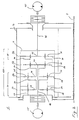
- a cable winch 1 which has a drum 2 rotatably mounted relative to a frame 3 of the cable winch 1 with an internal superimposing coupling gear 100, which consists of a single-stage main gear 20, a superimposing stage 52 coupled therewith and a second, single-stage gear 80 exists.
- An arrow marked “ ⁇ " indicates the direction of force of a load hanging on the winch rope.
- a hydraulic motor 15 drives the sun gear 53 of the superposition stage 52 via a drive shaft 16.
- the output web 54 of the planet gears 55, 56 of the superposition stage 52 forms, together with the sun gear 23 of the planet stage 22 of the main transmission 20, a hollow shaft through which the drive shaft 16 extends.
- the rotational movement of the sun gear 53 is transmitted from the output web 54 through this hollow shaft to the associated sun gear 23 and the planet gears 25, 26 of the output planetary stage 22.
- the planet gears of this first planetary stage 22 of the main transmission 20 are supported on the frame 3 of the cable winch 1, ie only rotatable about their own axes 24. They thus form the reaction element of the superimposed coupling gear 100.
- the planet gears 25, 26 and 27 supported on the frame 3 are finally at one internally toothed ring gear 28 of the same planetary stage 22 in meshing engagement.
- the ring gear 28 is in turn non-rotatably connected to the drum 2, for example by screwing.
- a second drive motor 45 which in the present exemplary embodiment is also designed as a hydraulic motor, is arranged. It drives the ring gear 58 of the superposition stage 52 via its drive shaft 46 mounted in the frame 3 and the second gear 80.
- the output web 54 in this case the planetary web, the superimposed rotary movements of the two hydraulic motors 15 and 45 are transmitted to the main transmission 20 and, via its ring gear 28, to the drum 2 of the cable winch 1.
- the second gear 80 is designed as a single-stage planetary gear 72, the sun gear 73 of which is driven by the second drive motor 45 via the drive shaft 46.
- the output to the ring gear 58 of the superposition stage 52 takes place via the planetary web 74 of the second gear 80.
- the entire superimposed coupling gear 100 is enclosed by a connecting bell 8, with which the ring gear 28 of the first planetary stage 22 and the ring gear 78 of the second gear 80 are connected in a rotationally fixed manner, for example by screwing.
- the bell 8 is rotatably mounted directly on the planet carrier 24 connected to the frame 3 of the main transmission 20 and connected to the drum 2 in a torsionally rigid manner.
- This construction enables an almost ideal, uniform branching of the power flows with subsequent merging in the connecting bell 8 via the ring gears 28 and 78 of the main gear 20 and the second gear 80 connected to it in a torsionally rigid manner.
- the drive is built very compactly inside the drum 2.
- the selected construction with the two drive motors 15 and 45 lying opposite one another and their aligned drive shafts 16 and 46 as well as their merging by means of the superposition step 52 benefit the stability of the construction.
- the winch drive is therefore almost exclusively subjected to torsion.
- 3 disk brakes 6 and 7 are arranged on the drive shafts 16 and 46 on opposite sides of the frame.
- the second brake 7, which is used to hold the drive shaft 46 of the second drive motor 45, does not need to absorb the entire reaction torque of the drum 2, but only the torque from the superposition stage 52, reduced by the reduction of the second gear 72.
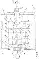
- the main transmission 20 or the second transmission 80 or both can be connected to additional planetary stages at the same time.
- Corresponding exemplary embodiments are shown in FIGS. 2 and 3.
- the rotary movement of the driven sun gear 53 of the superposition stage 52 is in turn via the planetary web 54 to the sun gear connected to it in a torsionally rigid manner 33 of the subsequent additional planetary stage 32 and finally transmitted from their planetary land 34 to the torsionally rigidly connected sun gear 23 of the output planetary stage 22 of the main transmission 20.
- the planetary land 54 of the superposition stage 52 forms together with the sun gear 33 the additional planetary stage 32 of the main gear 20, a hollow shaft.
- the drive shaft 16 Due to the two hollow shafts arranged one behind the other, the drive shaft 16 extends from the first drive motor 15 to the sun gear 53 of the superposition stage 52.
- the exemplary embodiment according to FIG. 2 with a two-stage main transmission 20 is a typical example of how the cable speed can be increased in part-load or idling mode by switching on a second drive motor 45.
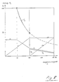
- the mode of operation of such an arrangement is shown by way of example in FIG. 5.
- the main motor in this case the first drive motor 15, has reached its maximum speed at a cable speed of 100% in accordance with the cable pull / cable speed diagram shown with linearly increasing motor speed n1 and is then still operated at this speed. With a given motor 15 and a given gear reduction, the highest possible cable speed is reached. Depending on the available drive power, the motor pressure p1 drops at around 50% rope speed with a further increasing motor speed n1.
- the second drive motor 45 is switched on at the maximum rope speed of 100% that can be achieved with a single drive motor 15. This results in an additional drive via the planetary stage 72 of the second gear 80 to the superposition stage 52. As the speed n2 of the second drive motor 45 increases, its engine pressure p2 gradually decreases together with the engine pressure p1 of the first drive motor 15.
- the cable speed can be increased continuously in a stepless manner in accordance with the power hyperbole as the cable pull slowly falls.
- the second gear 80 has a two-stage design with a first planetary stage 62 and a second planetary stage 72, both of which are connected in a rotationally rigid manner via their respective ring gears 68 and 78 via the gearbox 8 to the main transmission 20 and the drum 2 a heavy-duty stroke can be realized either with appropriate dimensioning of the entire cable winch 1 or very fine regulation of very slow cable speeds with the second and stationary first drive motor 45 or 15 running.
- FIGS. 1 to 3 show a superimposed coupling gear 100 with three planetary stages 22, 52 and 72, which is additionally equipped with a spur gear 51 for superimposing the torques of three drive motors 15 and 45.
- all drive motors 15 and 45 are arranged on the same end face of the cable winch 1.
- the first drive motor 15 drives the sun gear 53 of the superposition stage 52.
- the torque of two further drive motors 45 is transmitted via drive pinions 59 to the ring gear 58 provided with external teeth of the same superposition stage.
- this ring gear 58 can be produced, for example, as an internally and externally toothed ring gear or can be composed of an internally toothed and an externally toothed ring gear which are connected to one another in a torsionally rigid manner.
- the drive pinions 59 are rotatably mounted on the drive shafts 46 in a spur gear housing 4 which is connected to the frame 3 of the winch 1.
- this ring gear 58 is rotatably mounted in this spur gear housing 4 via a cup-shaped support 57.
- the free link of the superposition stage 52 - in this case the planet carrier 54 - is connected to the sun gear 73 of the second gear 72 in this exemplary embodiment.
- the described embodiment is not limited to the use of three drive motors 15 or 45, but can also be used using a first drive motor 15 with a single further drive motor 45 or with a plurality of drive motors 45, in particular arranged in a star shape around the first drive motor 15 Come into play.
- This arrangement of drive motors due to the comparatively large diameter of the cable winch 1 compared to the motors, in most cases the motors will not require any additional space.
Landscapes
- Engineering & Computer Science (AREA)
- Mechanical Engineering (AREA)
- Retarders (AREA)
- Jib Cranes (AREA)
Applications Claiming Priority (2)
| Application Number | Priority Date | Filing Date | Title |
|---|---|---|---|
| DE4134742 | 1991-10-21 | ||
| DE19914134742 DE4134742C1 (enExample) | 1991-10-21 | 1991-10-21 |
Publications (2)
| Publication Number | Publication Date |
|---|---|
| EP0538630A1 EP0538630A1 (de) | 1993-04-28 |
| EP0538630B1 true EP0538630B1 (de) | 1995-06-28 |
Family
ID=6443107
Family Applications (1)
| Application Number | Title | Priority Date | Filing Date |
|---|---|---|---|
| EP19920116135 Expired - Lifetime EP0538630B1 (de) | 1991-10-21 | 1992-09-21 | Antrieb für eine Seilwinde |
Country Status (3)
| Country | Link |
|---|---|
| EP (1) | EP0538630B1 (enExample) |
| DE (1) | DE4134742C1 (enExample) |
| NO (1) | NO303006B1 (enExample) |
Families Citing this family (2)
| Publication number | Priority date | Publication date | Assignee | Title |
|---|---|---|---|---|
| CN100559044C (zh) * | 2007-06-05 | 2009-11-11 | 唐志明 | 一种两级行星轮系传动的软起动装置 |
| ITTO20110834A1 (it) | 2011-09-20 | 2013-03-21 | Soilmec Spa | Sistema di controllo per una macchina di scavo e/o perforazione di terreni e macchina di scavo e/o perforazione comprendente tale sistema. |
Family Cites Families (6)
| Publication number | Priority date | Publication date | Assignee | Title |
|---|---|---|---|---|
| DE1481149A1 (de) * | 1966-10-12 | 1969-01-16 | Demag Zug Gmbh | Motoranordnung fuer Regalbedienungsgeraete u.dgl. |
| GB1181679A (en) * | 1967-12-02 | 1970-02-18 | Vickers Ltd | Improvements in or relating to Winches |
| FR2236773A1 (enExample) * | 1973-07-11 | 1975-02-07 | Z Im A M Gorkogo | |
| DE2601244C2 (de) * | 1976-01-15 | 1984-03-15 | Mannesmann AG, 4000 Düsseldorf | Trommelantrieb, insbesondere für eine Seilwinde |
| DE3041504A1 (de) * | 1980-11-04 | 1982-06-09 | Thyssen Industrie Ag, 4300 Essen | Trommelantrieb fuer krane |
| NL8302589A (nl) * | 1983-07-19 | 1985-02-18 | Davit Co Bv | Lier, in het bijzonder davitlier, evenals davitlier met deiningscompensator. |
-
1991
- 1991-10-21 DE DE19914134742 patent/DE4134742C1/de not_active Expired - Lifetime
-
1992
- 1992-09-21 EP EP19920116135 patent/EP0538630B1/de not_active Expired - Lifetime
- 1992-10-20 NO NO924052A patent/NO303006B1/no not_active IP Right Cessation
Also Published As
| Publication number | Publication date |
|---|---|
| NO924052L (no) | 1993-04-22 |
| EP0538630A1 (de) | 1993-04-28 |
| DE4134742C1 (enExample) | 1992-12-10 |
| NO303006B1 (no) | 1998-05-18 |
| NO924052D0 (no) | 1992-10-20 |
Similar Documents
| Publication | Publication Date | Title |
|---|---|---|
| EP2948406B1 (de) | Seilwinde | |
| DE2328353C3 (de) | Stufenloses, leistungsverzweigendes hydrostatisch-mechanisches Getriebe | |
| DE3935570C2 (de) | Gangwechselgetriebe für Kraftfahrzeuge | |
| EP2057030B1 (de) | Aktives differenzial | |
| DE112015002682T5 (de) | Elektrische bremsbetätigungsvorrichtung für fahrzeuge | |
| DE2758659B2 (de) | Hydrostatisch-mechanisches Getriebe mit Leistungsverzweigung | |
| EP0615077A1 (de) | Antrieb mit zwei Hydromotoren | |
| EP2979001A1 (de) | Getriebe für ein kraftfahrzeug | |
| DE3140442A1 (de) | Mehrstufiger winden- oder trommelantrieb | |
| DE3205208C2 (de) | Umlaufrädergetriebe | |
| DE2409914C2 (enExample) | ||
| DE2816777A1 (de) | Zweigwegegetriebe mit zwei drehzahlbereichen | |
| DE2502309C2 (de) | Leistungsverzweigende Getriebeanordnung | |
| DE2802368A1 (de) | Planetengetriebe | |
| DE3840572A1 (de) | Hydromechanisches getriebe fuer schwerfahrzeuge | |
| DE4201653A1 (de) | Automatikgetriebe | |
| EP0538662A2 (de) | Freifallwinde | |
| DE4206101A1 (de) | Hydromechanisches antriebssystem | |
| DE4206085C2 (de) | Hydromechanisches Antriebsaggregat für den hydrostatischen Fahrantrieb eines Fahrzeugs | |
| DE102004051306B4 (de) | Antriebsvorrichtung für Doppelschneckenextruder | |
| EP0538630B1 (de) | Antrieb für eine Seilwinde | |
| EP1416190A2 (de) | Leistungsverzweigtes Winkelgetriebe | |
| DE2405804A1 (de) | Hydrostatisches getriebe | |
| DE19717808C2 (de) | Freifallwinde mit einem zweistufigen Getriebe | |
| DE102020202417B3 (de) | Leistungsverzweigtes stufenloses Getriebe |
Legal Events
| Date | Code | Title | Description |
|---|---|---|---|
| PUAI | Public reference made under article 153(3) epc to a published international application that has entered the european phase |
Free format text: ORIGINAL CODE: 0009012 |
|
| AK | Designated contracting states |
Kind code of ref document: A1 Designated state(s): GB IT NL SE |
|
| 17P | Request for examination filed |
Effective date: 19930603 |
|
| 17Q | First examination report despatched |
Effective date: 19941021 |
|
| GRAA | (expected) grant |
Free format text: ORIGINAL CODE: 0009210 |
|
| ITF | It: translation for a ep patent filed | ||
| AK | Designated contracting states |
Kind code of ref document: B1 Designated state(s): GB IT NL SE |
|
| GBT | Gb: translation of ep patent filed (gb section 77(6)(a)/1977) |
Effective date: 19950630 |
|
| PLBQ | Unpublished change to opponent data |
Free format text: ORIGINAL CODE: EPIDOS OPPO |
|
| PLBI | Opposition filed |
Free format text: ORIGINAL CODE: 0009260 |
|
| PLBF | Reply of patent proprietor to notice(s) of opposition |
Free format text: ORIGINAL CODE: EPIDOS OBSO |
|
| 26 | Opposition filed |
Opponent name: SIEBENHAAR ANTRIEBSTECHNIK GMBH Effective date: 19960321 |
|
| NLR1 | Nl: opposition has been filed with the epo |
Opponent name: SIEBENHAAR ANTRIEBSTECHNIK GMBH |
|
| PLBF | Reply of patent proprietor to notice(s) of opposition |
Free format text: ORIGINAL CODE: EPIDOS OBSO |
|
| PLBL | Opposition procedure terminated |
Free format text: ORIGINAL CODE: EPIDOS OPPC |
|
| PLBM | Termination of opposition procedure: date of legal effect published |
Free format text: ORIGINAL CODE: 0009276 |
|
| 27C | Opposition proceedings terminated |
Effective date: 19961128 |
|
| NLR2 | Nl: decision of opposition | ||
| REG | Reference to a national code |
Ref country code: GB Ref legal event code: IF02 |
|
| PGFP | Annual fee paid to national office [announced via postgrant information from national office to epo] |
Ref country code: GB Payment date: 20090922 Year of fee payment: 18 Ref country code: NL Payment date: 20090915 Year of fee payment: 18 Ref country code: SE Payment date: 20090915 Year of fee payment: 18 |
|
| PGFP | Annual fee paid to national office [announced via postgrant information from national office to epo] |
Ref country code: IT Payment date: 20090926 Year of fee payment: 18 |
|
| REG | Reference to a national code |
Ref country code: NL Ref legal event code: V1 Effective date: 20110401 |
|
| REG | Reference to a national code |
Ref country code: SE Ref legal event code: EUG |
|
| GBPC | Gb: european patent ceased through non-payment of renewal fee |
Effective date: 20100921 |
|
| PG25 | Lapsed in a contracting state [announced via postgrant information from national office to epo] |
Ref country code: IT Free format text: LAPSE BECAUSE OF NON-PAYMENT OF DUE FEES Effective date: 20100921 |
|
| PG25 | Lapsed in a contracting state [announced via postgrant information from national office to epo] |
Ref country code: NL Free format text: LAPSE BECAUSE OF NON-PAYMENT OF DUE FEES Effective date: 20110401 Ref country code: GB Free format text: LAPSE BECAUSE OF NON-PAYMENT OF DUE FEES Effective date: 20100921 |
|
| PG25 | Lapsed in a contracting state [announced via postgrant information from national office to epo] |
Ref country code: SE Free format text: LAPSE BECAUSE OF NON-PAYMENT OF DUE FEES Effective date: 20100922 |