EP0538540B1 - Mechanisches Verbindungselement für montierbare Möbeleinheit, insbesondere für freistehende und geschlossene Verteileranlagen - Google Patents
Mechanisches Verbindungselement für montierbare Möbeleinheit, insbesondere für freistehende und geschlossene Verteileranlagen Download PDFInfo
- Publication number
- EP0538540B1 EP0538540B1 EP19910830452 EP91830452A EP0538540B1 EP 0538540 B1 EP0538540 B1 EP 0538540B1 EP 19910830452 EP19910830452 EP 19910830452 EP 91830452 A EP91830452 A EP 91830452A EP 0538540 B1 EP0538540 B1 EP 0538540B1
- Authority
- EP
- European Patent Office
- Prior art keywords
- head
- furniture
- connection element
- item
- base
- Prior art date
- Legal status (The legal status is an assumption and is not a legal conclusion. Google has not performed a legal analysis and makes no representation as to the accuracy of the status listed.)
- Expired - Lifetime
Links
Images


Classifications
-
- H—ELECTRICITY
- H02—GENERATION; CONVERSION OR DISTRIBUTION OF ELECTRIC POWER
- H02B—BOARDS, SUBSTATIONS OR SWITCHING ARRANGEMENTS FOR THE SUPPLY OR DISTRIBUTION OF ELECTRIC POWER
- H02B1/00—Frameworks, boards, panels, desks, casings; Details of substations or switching arrangements
- H02B1/26—Casings; Parts thereof or accessories therefor
- H02B1/30—Cabinet-type casings; Parts thereof or accessories therefor
- H02B1/38—Hinged covers or doors
-
- A—HUMAN NECESSITIES
- A47—FURNITURE; DOMESTIC ARTICLES OR APPLIANCES; COFFEE MILLS; SPICE MILLS; SUCTION CLEANERS IN GENERAL
- A47B—TABLES; DESKS; OFFICE FURNITURE; CABINETS; DRAWERS; GENERAL DETAILS OF FURNITURE
- A47B47/00—Cabinets, racks or shelf units, characterised by features related to dismountability or building-up from elements
- A47B47/02—Cabinets, racks or shelf units, characterised by features related to dismountability or building-up from elements made of metal only
- A47B47/03—Cabinets, racks or shelf units, characterised by features related to dismountability or building-up from elements made of metal only with panels separate from the frame
-
- A—HUMAN NECESSITIES
- A47—FURNITURE; DOMESTIC ARTICLES OR APPLIANCES; COFFEE MILLS; SPICE MILLS; SUCTION CLEANERS IN GENERAL
- A47B—TABLES; DESKS; OFFICE FURNITURE; CABINETS; DRAWERS; GENERAL DETAILS OF FURNITURE
- A47B87/00—Sectional furniture, i.e. combinations of complete furniture units, e.g. assemblies of furniture units of the same kind such as linkable cabinets, tables, racks or shelf units
-
- H—ELECTRICITY
- H02—GENERATION; CONVERSION OR DISTRIBUTION OF ELECTRIC POWER
- H02B—BOARDS, SUBSTATIONS OR SWITCHING ARRANGEMENTS FOR THE SUPPLY OR DISTRIBUTION OF ELECTRIC POWER
- H02B1/00—Frameworks, boards, panels, desks, casings; Details of substations or switching arrangements
- H02B1/26—Casings; Parts thereof or accessories therefor
- H02B1/30—Cabinet-type casings; Parts thereof or accessories therefor
- H02B1/301—Cabinet-type casings; Parts thereof or accessories therefor mainly consisting of a frame onto which plates are mounted
-
- H—ELECTRICITY
- H02—GENERATION; CONVERSION OR DISTRIBUTION OF ELECTRIC POWER
- H02B—BOARDS, SUBSTATIONS OR SWITCHING ARRANGEMENTS FOR THE SUPPLY OR DISTRIBUTION OF ELECTRIC POWER
- H02B1/00—Frameworks, boards, panels, desks, casings; Details of substations or switching arrangements
- H02B1/26—Casings; Parts thereof or accessories therefor
- H02B1/30—Cabinet-type casings; Parts thereof or accessories therefor
- H02B1/308—Mounting of cabinets together
Definitions
- This invention relates to a mechanical connection element as defined in the preamble of claim 1 for erecting unit furniture, particularly but not solely intended for erecting electric boards of both the exposed and enclosed types.
- unit furniture enjoy widespread acceptance on account of they being adapted to be assembled modularly into a number of different combinations to meet varying user's dimension and design demands.
- a typical example is provided by built-up space frames of metal, whereby a suitable combination of uprights and shelves can provide a full range of space frame configurations.
- Such cabinet-mounted boards, or cabinets for brevity are utilized to provide weather protection for electrical equipment against dust and rain contamination, for instance, as well as to inhibit unauthorized access to such equipment, and are available commercially in many different sizes and shapes to provide the user with a choice to suit.
- Cabinets so constructed are bulky, difficult to transport, and require fairly large storage areas.
- the underlying technical problem of this invention is to provide a mechanical connection element for erecting unit furniture, which can lower the number of parts involved in assembling structures, even fairly complex ones like the aforesaid distribution boards, and thus obviate the shortcomings with which the prior art is beset.
- a mechanical connection element for erecting unit furniture comprising a base having first means of attachment to a structural part of an item of furniture, a web extending from said base, and a head formed on the remote web end from the base, said head being formed with a first pair of holes aligned along a common axis parallel to the base and constituting sockets for a hinge pin to hingedly interconnect two structural parts of the item of furniture through said element, characterized in that said head comprises second releasable attachment means for a head of a second connection element or another structural part of the item of furniture.
- Shown at 1 in the drawing figures is a cabinet for electrical equipment embodying this invention.
- This cabinet 1 comprises a frame 2 whereto there are mounted, using mechanical connection elements 3, such curtaining members as panels 4a, trimming strips 4b,c and door wings 4d.
- the cabinet frame 2 is formed by assembling section bars 201 together which are pre-punched at pitch intervals with holes and openings, respectively indicated at 202a,b.
- the section bars 201 have a symmetrical cross-sectional shape about a plane whose trace is indicated at A in Figure 8; the trace line A separates two identical parts, each having four straight sides 203a,b,c,d; sides 203a,b being perpendicular to each other and parallel to sides 203c,d, respectively.
- Each trimming strip 4b ( Figure 8) comprises two bodies 412, 413 of box-type construction running along the opposed longitudinal edges of an exposed surface designated 411.
- the bodies 412, 413 border a channel-like seat 410.
- a ridge 415 extends in the seat 410 between said bodies 412, 413 with spacer functions as explained hereinafter.
- Respective lugs 416, 417 extend from the bodies 412, 413 and have hooked free ends.
- the trimming strip 4c ( Figure 7) comprises a box-type body 421 whence two lugs 423a,b extend symmetrically gullwing-fashion.
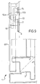
- the mechanical connection element 3 ( Figures 2-6) comprises a plate-like base 6 having two opposed longitudinal sides 9a,b.
- Side 9a is straight and formed with a groove 10a which fully spans its length;
- side 9b is a mixed pattern with a middle portion defining a recess 9c included between end portions occupied by a groove 10b.
- the base 6 is provided with two oppositely located holes 7a,b.
- located intermediate to the holes 7a,b are two cylindrical projections having complementary shapes to the openings 202b formed in the section bars 201 for alignment purposes, that is to ensure proper location and alignment of element 3 to its corresponding section bar 201.
- Such holes 7a,b and the projections 8a,b jointly constitute a first means of attaching the mechanical connection element 3 to the frame 2.
- a web 12 extends square to the base 6 at the location of the recess 9c.
- the web 12 is bent ell-like and has a dog 13 formed integrally on its opposite wall from the recess 9c, which dog is adapted to provide abutment for a latch 14 ( Figure 9) in a manner to be explained.
- a head 15 defined on the remote end of the web 12 from the base 6 is a head 15 defining two opposed surfaces 16, 17.
- Surface 17 is patterned into a tenon 18 and a mortise 19 lying transverse to the base 6.
- the tenon 18 and mortise 19 are passed through by respective holes 23, 24 of which hole 23 is threaded. At the entrance of the holes 23, 24 facing toward the surface 17, there are respectively provided an elevation 23a and a mating flare 24a.
- the tenon 18 and mortise 19 with their corresponding holes 23, 24 jointly constitute a second means for end fastening together two mechanical connection elements 3, or uniting one of such elements 3 with a panel 4a.
- the head 15 is drilled along a direction parallel to the base 6 and perpendicular to the holes 23, 24 so as to define two holes 25a,b providing a socket for a hinge pin 26 ( Figures 2 and 7).
- the mechanical connection element 3 is attached to the section bar 201 of the frame 2 by means of the first fasteners, that is with the projections 8a,b received in the holes 202b and with screws or rivets 204 ( Figures 7 and 8) correspondingly fitted into the holes 7a,b.
- the panels 4a ( Figure 8) are attached rigidly to the mechanical connection element 3 by threaded engagement of a screw 27 in the threaded hole 23 of the head 15, thereby as the mechanical connection element 3 is attached to the frame 2, the panel 4a is made fast with said frame.
- Two mechanical connection elements 3 can be end joined, with the tenon 18 of one received matingly in the mortise of the other, and vice versa. This joint is completed by passing two screws 28 through the holes 24 and threading them into the holes 23 ( Figure 7).
- Two sections bars 201 can be coupled together by securing two mechanical connection elements 3 thereon through their respective bases 6 and joining the heads 15 together as explained hereinabove ( Figure 7).
- the door wings 4d ( Figure 7) can be hinge-connected to the frame 2 by using an element 3 provided with a pin 26, as the first hinge member, and a corresponding eye 29 rigid with the door wing 4d, as the second hinge member.
- the hinge pin 26 would be received rotatably in the hinge eye 29.
- the door wing would be provided with a conventional latch 14 ( Figure 9) which is mounted slidably at the free edge of the door wing, parallel to the hinge axis.
- the latch 14 has a bifurcated free end, and between its prongs 14a,b, there is arranged to abut the dog 13 of an element 3 mounted at a suitable location on the frame 2.
- the trimming strip 4c ( Figure 7), to be fitted over the joint between two adjacent section bars, is secured on the cabinet 1 by snap engaging the free ends of the lugs 423a,b into the grooves 10b of the mechanical connection elements 3, with the section bar body 421 to bear onto the heads 15 of the two mechanical connection elements 3.
- the trimming strip 4b ( Figure 5) is made fast with the cabinet 1 by snap engaging the hooked ends of the lugs 416, 417 into the grooves 10a and 21 of one element 3. Accordingly, this mechanical connection element will have its head 15 and part of its web 12 received in the channel-like seat 410.
- the ridge 415 acts as a spacer to the surface 17 of the head 15.
- Figure 10 shows two mechanical connection elements according to the invention which have minor changes relative to the elements shown in Figure 2.
- the most relevant change is a different shape of the mixed pattern, referred to as 9b', whose end portions are provided with a groove 10b' on the surface of base 6 facing toward the head 15. This shape results in plastic profiles being better fastened and manufacturing of the connection elements by moulding being easier.
- the invention allows unit furniture to be manufactured for sale as assembly kits including the pre-punched section bars required for assembling the frame 2, the curtaining means 4a,b,c,d, and mechanical connection elements 3 of a single type.
- These mechanical connection elements enable the various types of curtaining members to be mounted to the frame, either fixedly or pivotally, can provide an abutment for a closure latch, and a means of fastening together section bars from different cabinets to tie adjacent cabinets together into a unitary whole.
- such cabinets can be assembled in the field in a particularly simple way, thus achieving savings in resources, both in terms of time, and storage space and related costs.
Landscapes
- Engineering & Computer Science (AREA)
- Power Engineering (AREA)
- Furniture Connections (AREA)
- Connection Of Plates (AREA)
- Combinations Of Kitchen Furniture (AREA)
- Assembled Shelves (AREA)
- Hinges (AREA)
Claims (9)
- Ein mechanisches Verbindungselement zum Aufrichten von Einheitsmobiliar, welches eine Basis (6) mit einer ersten Einrichtung (7a, b; 8a, b; 204) zur Befestigung an ein strukturelles Teil (201) eines Mobiliargegenstands, einen Steg (12), der sich von der Basis erstreckt, und einen Kopf (15) aufweist, der auf dem von der Basis entfernten Stegende gebildet ist, wobei der Kopf mit einem ersten Paar von Löchern (25a, b) gebildet ist, die entlang einer gemeinsamen Achse parallel zu der Basis ausgerichtet sind und Sockel für einen Scharnierstift (26) bilden, damit zwei strukturelle Teile des Möbelgegenstandes durch das Element scharniermäßig miteinander verbunden werden, dadurch gekennzeichnet, daß der Kopf eine zweite lösbare Befestigungseinrichtung (18, 19; 23, 24) für einen Kopf eines zweiten Verbindungselements oder eines anderen strukturellen Teils des Mobiliargegenstandes aufweist.
- Ein Element gemäß Anspruch 1, bei dem die zweite Befestigungseinrichtung mindestens ein zweites Lochpaar (23, 24) durch den Kopf aufweist, das eine zu der Achse des ersten Paars (25a, b) senkrechte Achse aufweist.
- Ein Element gemäß entweder Anspruch 1 oder Anspruch 2, bei dem der Kopf eine Oberfläche (17) in einem Muster aufweist, das mit einer entsprechenden Oberfläche des Kopfs eines zweiten Verbindungselements zusammenpaßt.
- Ein Element gemäß Anspruch 3, bei dem die gemusterte Oberfläche zumindest einen Zapfen (18) und zumindest eine Nut (19) aufweist, die angeordnet sind, um nebeneinander und zueinander parallel zu liegen.
- Ein Element gemäß Anspruch 4, bei dem der Zapfen und die Nut sowohl in der Konturform als auch in der Anordnung auf dem Kopf zusammenpassende Entwürfe sind.
- Ein Element gemäß Anspruch 2, bei dem eines (23) des zweiten Lochpaares mit einem Gewinde versehen ist, wobei das andere (24) glatt ist.
- Ein Element gemäß Anspruch 2, bei dem der Steg (12) mit einem nasenförmigen Ansatz (13) gebildet ist, der angepaßt ist, um ein Anstoßen für den Stab eines Riegels (14) zu schaffen.
- Ein Einheitsmobiliargegenstand, der einen Rahmen (2) und eine Vorhangeinrichtung (4a, b, c, d) für denselben aufweist, die durch mindestens ein Verbindungselement (3) gemäß einem oder mehreren der vorhergehenden Ansprüche zusammengehalten werden.
- Ein Mobiliargegenstand gemäß Anspruch 8, bei dem die Vorhangeinrichtung Abschnittsbalken (4b, c) mit mindestens einem Ansatz (416, 417; 423a, b) aufweist, der angepaßt ist, um in eine entsprechende Rille (10a, b; 21), die in dem Verbindungselement (3) gebildet ist, einschnappmäßig zu passen.
Priority Applications (3)
| Application Number | Priority Date | Filing Date | Title |
|---|---|---|---|
| ES91830452T ES2098339T3 (es) | 1991-10-24 | 1991-10-24 | Un elemento de conexion mecanica para construir mobiliario unitario, en particular para cuadros de distribucion al descubierto o encerrados. |
| EP19910830452 EP0538540B1 (de) | 1991-10-24 | 1991-10-24 | Mechanisches Verbindungselement für montierbare Möbeleinheit, insbesondere für freistehende und geschlossene Verteileranlagen |
| DE1991623587 DE69123587T2 (de) | 1991-10-24 | 1991-10-24 | Mechanisches Verbindungselement für montierbare Möbeleinheit, insbesondere für freistehende und geschlossene Verteileranlagen |
Applications Claiming Priority (1)
| Application Number | Priority Date | Filing Date | Title |
|---|---|---|---|
| EP19910830452 EP0538540B1 (de) | 1991-10-24 | 1991-10-24 | Mechanisches Verbindungselement für montierbare Möbeleinheit, insbesondere für freistehende und geschlossene Verteileranlagen |
Publications (2)
| Publication Number | Publication Date |
|---|---|
| EP0538540A1 EP0538540A1 (de) | 1993-04-28 |
| EP0538540B1 true EP0538540B1 (de) | 1996-12-11 |
Family
ID=8208977
Family Applications (1)
| Application Number | Title | Priority Date | Filing Date |
|---|---|---|---|
| EP19910830452 Expired - Lifetime EP0538540B1 (de) | 1991-10-24 | 1991-10-24 | Mechanisches Verbindungselement für montierbare Möbeleinheit, insbesondere für freistehende und geschlossene Verteileranlagen |
Country Status (3)
| Country | Link |
|---|---|
| EP (1) | EP0538540B1 (de) |
| DE (1) | DE69123587T2 (de) |
| ES (1) | ES2098339T3 (de) |
Families Citing this family (6)
| Publication number | Priority date | Publication date | Assignee | Title |
|---|---|---|---|---|
| DE4336187C2 (de) * | 1993-10-23 | 1996-12-12 | Loh Kg Rittal Werk | Rahmenschenkel für ein Rahmengestell eines Schaltschrankes |
| IT1265407B1 (it) * | 1993-12-17 | 1996-11-22 | Italtel Spa | Armadio metallico a tenuta, in particolare per l'alloggiamento di apparecchiature elettriche ed elettroniche |
| IT1291616B1 (it) * | 1997-04-18 | 1999-01-11 | Abb Turati S P A | Intelaiatura con dispositivo di collegamento e di supporto per profilati e pannelli di armadi |
| DE19737667C1 (de) * | 1997-08-29 | 1999-06-02 | Loh Kg Rittal Werk | Reihe von aneinandergereihten Schaltschränken |
| DE10328403A1 (de) * | 2003-06-25 | 2005-01-13 | Abb Patent Gmbh | Befestigungsbock |
| EP3070796B1 (de) * | 2015-03-17 | 2017-11-08 | ABB S.p.A. | Verbindungselement zum mechanischen verbinden von schaltanlagenrahmen |
Family Cites Families (2)
| Publication number | Priority date | Publication date | Assignee | Title |
|---|---|---|---|---|
| US3265419A (en) * | 1963-12-30 | 1966-08-09 | Honeywell Inc | Cabinet structure |
| AT390155B (de) * | 1982-02-16 | 1990-03-26 | Hellopa Anstalt | Schrank od. dgl. behaeltnis, insbesondere zur aufbewahrung von schaltorganen |
-
1991
- 1991-10-24 DE DE1991623587 patent/DE69123587T2/de not_active Expired - Fee Related
- 1991-10-24 ES ES91830452T patent/ES2098339T3/es not_active Expired - Lifetime
- 1991-10-24 EP EP19910830452 patent/EP0538540B1/de not_active Expired - Lifetime
Also Published As
| Publication number | Publication date |
|---|---|
| EP0538540A1 (de) | 1993-04-28 |
| DE69123587T2 (de) | 1997-07-10 |
| DE69123587D1 (de) | 1997-01-23 |
| ES2098339T3 (es) | 1997-05-01 |
Similar Documents
| Publication | Publication Date | Title |
|---|---|---|
| US4544069A (en) | Modular elements for composing frames for the construction of cabinet structures and containers for electrical, electromechanical and electronic components, for internal and external use | |
| US5546718A (en) | Partition wall | |
| US5536078A (en) | Modular furniture system | |
| EP0538540B1 (de) | Mechanisches Verbindungselement für montierbare Möbeleinheit, insbesondere für freistehende und geschlossene Verteileranlagen | |
| US20190078317A1 (en) | Panel with defined fastener location | |
| US4455102A (en) | System for assembling and fixing panels | |
| US5713649A (en) | Method of manufacturing a box container or cabinet | |
| US4656801A (en) | Frame structures | |
| US20050166492A1 (en) | Plastic batten shutter | |
| US4644993A (en) | Modular panel system | |
| US4527364A (en) | Corner assembly of structural members | |
| DE4139341C1 (de) | ||
| EP0383427B1 (de) | Reklametafel-Bausatz | |
| EP0399595B1 (de) | Mittels Verbindungsteilen zusammengebauter Schrank für elektrische Installationen | |
| DE69724026T2 (de) | Ausbaubare Schaltschrank mit integriertem Sockel | |
| JP3865480B2 (ja) | 組立式保管庫 | |
| EP3970561B1 (de) | Befestigungssystem aus länglichen elementen mit verbindungselement und struktur mit befestigungssystem für möbel, möbel oder möbelzubehörteile | |
| KR200295294Y1 (ko) | 천장용 판넬 조립구조 | |
| EP0377780B1 (de) | Multifunktionsleiste | |
| KR200395858Y1 (ko) | 가구용 프레임의 조립구조 | |
| JPS6133838Y2 (de) | ||
| GB2052956A (en) | Frame constructions | |
| JPH09302962A (ja) | ブースの組立構造 | |
| JPH063049Y2 (ja) | 間仕切装置 | |
| JPH07150853A (ja) | 折り戸 |
Legal Events
| Date | Code | Title | Description |
|---|---|---|---|
| PUAI | Public reference made under article 153(3) epc to a published international application that has entered the european phase |
Free format text: ORIGINAL CODE: 0009012 |
|
| AK | Designated contracting states |
Kind code of ref document: A1 Designated state(s): AT BE CH DE DK ES FR GB GR IT LI LU NL SE |
|
| RBV | Designated contracting states (corrected) |
Designated state(s): BE DE ES FR GB IT |
|
| 17P | Request for examination filed |
Effective date: 19930607 |
|
| 17Q | First examination report despatched |
Effective date: 19941207 |
|
| GRAH | Despatch of communication of intention to grant a patent |
Free format text: ORIGINAL CODE: EPIDOS IGRA |
|
| GRAH | Despatch of communication of intention to grant a patent |
Free format text: ORIGINAL CODE: EPIDOS IGRA |
|
| RAP1 | Party data changed (applicant data changed or rights of an application transferred) |
Owner name: BTICINO S.P.A. |
|
| GRAA | (expected) grant |
Free format text: ORIGINAL CODE: 0009210 |
|
| AK | Designated contracting states |
Kind code of ref document: B1 Designated state(s): BE DE ES FR GB IT |
|
| REF | Corresponds to: |
Ref document number: 69123587 Country of ref document: DE Date of ref document: 19970123 |
|
| ITF | It: translation for a ep patent filed |
Owner name: 0403;05MIFJACOBACCI & PERANI S.P.A. |
|
| ET | Fr: translation filed | ||
| REG | Reference to a national code |
Ref country code: ES Ref legal event code: FG2A Ref document number: 2098339 Country of ref document: ES Kind code of ref document: T3 |
|
| PLBE | No opposition filed within time limit |
Free format text: ORIGINAL CODE: 0009261 |
|
| STAA | Information on the status of an ep patent application or granted ep patent |
Free format text: STATUS: NO OPPOSITION FILED WITHIN TIME LIMIT |
|
| 26N | No opposition filed | ||
| REG | Reference to a national code |
Ref country code: GB Ref legal event code: IF02 |
|
| PGFP | Annual fee paid to national office [announced via postgrant information from national office to epo] |
Ref country code: GB Payment date: 20080926 Year of fee payment: 18 |
|
| PGFP | Annual fee paid to national office [announced via postgrant information from national office to epo] |
Ref country code: DE Payment date: 20081030 Year of fee payment: 18 |
|
| PGFP | Annual fee paid to national office [announced via postgrant information from national office to epo] |
Ref country code: ES Payment date: 20091006 Year of fee payment: 19 |
|
| PGFP | Annual fee paid to national office [announced via postgrant information from national office to epo] |
Ref country code: BE Payment date: 20091001 Year of fee payment: 19 |
|
| PG25 | Lapsed in a contracting state [announced via postgrant information from national office to epo] |
Ref country code: DE Free format text: LAPSE BECAUSE OF NON-PAYMENT OF DUE FEES Effective date: 20100501 |
|
| PG25 | Lapsed in a contracting state [announced via postgrant information from national office to epo] |
Ref country code: GB Free format text: LAPSE BECAUSE OF NON-PAYMENT OF DUE FEES Effective date: 20091024 |
|
| PGFP | Annual fee paid to national office [announced via postgrant information from national office to epo] |
Ref country code: IT Payment date: 20100925 Year of fee payment: 20 |
|
| PGFP | Annual fee paid to national office [announced via postgrant information from national office to epo] |
Ref country code: FR Payment date: 20101115 Year of fee payment: 20 |
|
| BERE | Be: lapsed |
Owner name: *BTICINO S.P.A. Effective date: 20101031 |
|
| PG25 | Lapsed in a contracting state [announced via postgrant information from national office to epo] |
Ref country code: BE Free format text: LAPSE BECAUSE OF NON-PAYMENT OF DUE FEES Effective date: 20101031 |
|
| REG | Reference to a national code |
Ref country code: ES Ref legal event code: FD2A Effective date: 20111118 |
|
| PG25 | Lapsed in a contracting state [announced via postgrant information from national office to epo] |
Ref country code: ES Free format text: LAPSE BECAUSE OF NON-PAYMENT OF DUE FEES Effective date: 20101025 |