EP0537588A2 - Système de transmission à multiplex temporel pour des services différents de données - Google Patents
Système de transmission à multiplex temporel pour des services différents de données Download PDFInfo
- Publication number
- EP0537588A2 EP0537588A2 EP92116990A EP92116990A EP0537588A2 EP 0537588 A2 EP0537588 A2 EP 0537588A2 EP 92116990 A EP92116990 A EP 92116990A EP 92116990 A EP92116990 A EP 92116990A EP 0537588 A2 EP0537588 A2 EP 0537588A2
- Authority
- EP
- European Patent Office
- Prior art keywords
- transmission system
- time
- data
- division multiplex
- lzs
- Prior art date
- Legal status (The legal status is an assumption and is not a legal conclusion. Google has not performed a legal analysis and makes no representation as to the accuracy of the status listed.)
- Ceased
Links
Images


Classifications
-
- H—ELECTRICITY
- H04—ELECTRIC COMMUNICATION TECHNIQUE
- H04J—MULTIPLEX COMMUNICATION
- H04J3/00—Time-division multiplex systems
- H04J3/02—Details
- H04J3/06—Synchronising arrangements
- H04J3/062—Synchronisation of signals having the same nominal but fluctuating bit rates, e.g. using buffers
- H04J3/0626—Synchronisation of signals having the same nominal but fluctuating bit rates, e.g. using buffers plesiochronous multiplexing systems, e.g. plesiochronous digital hierarchy [PDH], jitter attenuators
-
- H—ELECTRICITY
- H04—ELECTRIC COMMUNICATION TECHNIQUE
- H04J—MULTIPLEX COMMUNICATION
- H04J3/00—Time-division multiplex systems
- H04J3/16—Time-division multiplex systems in which the time allocation to individual channels within a transmission cycle is variable, e.g. to accommodate varying complexity of signals, to vary number of channels transmitted
- H04J3/1605—Fixed allocated frame structures
- H04J3/1623—Plesiochronous digital hierarchy [PDH]
- H04J3/1647—Subrate or multislot multiplexing
Definitions
- the invention is based on a transmission system according to the preamble of patent claim 1.
- a digital time division multiplex transmission system is known from NTG technical reports, volume 80, March 1982, pages 157 to 164, which can be constructed as a line-like as well as a star-shaped branching network.
- Decentralized bus stations are connected to a central bus station, for example via a loop network.
- Several participants can be connected to the decentralized bus stations.
- every participant can send a connection request with equal rights.
- the bus connecting the decentralized bus stations of a subnetwork consists of a send and a receive line.
- the information fed into a transmission line by the bus stations is redirected at a data redirection point into the reception line of the respective subnetworks, from which the bus stations take the data directed to them.
- the transmission takes place in time division multiplex, so that this system requires a clock center and a frame synchronization generator, which are expediently housed in the central bus station.
- Each transmission line is a runtime compensation unit in the form of a runtime memory assigned, which adjusts the runtime differences between the frame on the transmission line and the frame of the frame synchronization generator.
- Each subscriber station receives the sum of all data available in the network, but only evaluates those that are addressed to it.
- the data to be sent out by a bus station is always fed in on the transmission line in the same time channel and thus found on the same time channel (time slot).
- the initiating subscriber searches for a free time channel on the reception line at the start of a connection and, if this is found, sends a call to a desired other subscriber in the same time channel of the transmission line. The sum of all transmitted data is transmitted to the participants in the same order on the receive line.
- an adapted number of terminals processing different types of communication must be connectable to one another in any combination with regard to the data transmission quantity and the data transmission speed as well as with regard to the transmission method.
- the object of the present invention is to overcome disadvantages of known systems.
- the collisions of data packets should be kept as low as possible and on the other hand an additional flow control in the sending decentralized bus stations should be avoided.
- This object is achieved by the features of patent claim 1.
- the other claims show advantageous developments.
- the solution according to the invention reduces the number of collisions with a reduction in the signal propagation times in the transmission network, so that the bus stations willing to transmit can detect the occupancy of the channels (areas) provided for data transmission on the transmission lines as quickly as possible via the reception line.
- Another feature of the star-shaped and star-shaped branched network structures used here namely combining the transmission lines at one or more points in the network, and branching the sum data from all transmission lines in parallel into the receiving lines at one point in the network, allows transmission lines to be separated exclude the formation of sums and thus avoid faults in other line sections.
- the system is flexible and can be easily adapted to different communication needs. Different services can be operated side-by-side undisturbed and without adverse interference.
- FIG. 1 shows a star-shaped communication system, built up with the system components central bus station MBU as a branching unit and decentral bus station BTU within the subnetworks. All bus stations are connected to one another via a transmission line SL and a reception line EL connected.
- the central bus station MBU has only the function of a master clock and determines the time-division multiplex frame by periodically sending the frame identification words into the receive lines.
- Each decentralized bus station is equipped with a sync reflex, which is automatically activated in the last decentralized bus station at the end of each transmission line AL and transmits the empty time-division multiplex frame with the system clock, derived from the clock of the reception line, into the transmission line.
- the data to be sent out by the decentralized bus stations BTU are sent to the transmission line SL.
- the data in the runtime compensation units assigned to each transmission line SL e.g. B. delay memories LZS so delayed that they are controlled by the frame synchronizing generator RG, read out clock and frame synchronously and sent out again in parallel via the summing module SM in all receiving lines EL.
- Each decentralized BTU bus station receives the sum of all data sent in the network, but only evaluates those that are intended for it.
- a line module LM is assigned to each reception and transmission line, each consisting of a transmission unit MS and a reception unit ME. Both the frame generator RG and the runtime memory LZS are controlled via control lines STL by a control device (network management) NM.
- a control device network management
- NM network management
- a linking device consisting of two OR gates can be used.
- the participants z. B. Telephone equipment, data terminals, computers that want to connect, are (not shown) each connected to one of the decentralized BTU bus stations.
- a star-shaped communication network is expanded to form a star-branched communication network.
- the master function of the central bus station MBU, as described in FIG. 1, with the summing module SM for the formation of the sum information and parallel transmission in all reception lines is retained.
- Other central bus stations SBU inserted into the network are operated as slave stations and synchronize themselves with the frame synchronization generator RG to the master clock received from the central bus station MBU via the receive line EL of the connecting line AL1n and send the received data in parallel to all receiving lines EL of the connecting lines AL21 to AL2n .
- the data of the transmission lines SL of the connecting lines AL21 to AL2n are delayed in the assigned delay memories LZS in such a way that, controlled by the frame synchronizing generator RG as slave clock, they are read out in clock and frame synchronism and transmitted via the summing module SM into the outgoing transmission line SL of the connecting line AL1n and the central bus station MBU are fed.
- the runtime compensation unit in the form of the runtime memory LZS supplements the runtime differences of the subnets to an integer multiple of the time division multiplex frame duration.
- central bus stations MBU and SBU can be preset manually or are used by network management NM when configuring the network, e.g. B. automatically controlled by software.
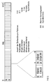
- FIG. 3 shows a time-division multiplex frame of 512 time channels for the information transmission in the communication system.
- Each time channel is a time division multiple access channel of e.g. B. 16 kbit / s.
- the first time channel contains the frame identifier RK.
- the remaining time channels are available for message transmission.
- the time channels are assigned to the terminal devices (subscribers) connected to the decentralized bus stations BTU only for the duration of the message connection. For this reason, each signaling connection is preceded and followed by a signaling phase.
- the signaling information characterized by the signal identification bits Sn (S1 and S2), are transmitted as in-band signaling in the same time channel or time channels in which the information is subsequently transmitted.
- short message packets such as B.
- the delay times consisting of the signal propagation time in the transmission network and the flow control (e.g. upstream signaling phase as in circuit-switched services) are disruptive and reduce the data throughput by such Communication system. Therefore, these services are in each case with the least delay in the next free time channels of the time division multiplex frame reserved for them inserted, as will be explained in connection with FIG. 5.
- circuit-switched and packet-oriented services are accommodated side by side in assigned service areas, each consisting of one or more time channels within a time-division multiplex frame according to a predetermined pattern.
- the areas are independent of one another and cannot be influenced by one another.
- the data of the transmission lines SL are fed to the runtime memories LZS via the reception modules EM of the line modules LM.
- the data are read out in synchronism with the clock and frame from all the runtime memories LZS, fed to the summing module SM in parallel and combined to form a sum bit stream, which can be implemented in the simplest manner with an OR function, and then in parallel in all receive lines EL the connecting lines AL11 to AL1n is transmitted.
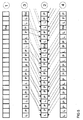
- the associated timing diagrams in FIG. 5 show the data sequences at the locations of the central bus station MBU marked with the numbers 1 to 4. So position 1 shows the empty time-division multiplex frame from the frame synchronization generator RG.
- Positions 3 and 4 show the multiplex signals of two transmission lines SL read into the delay time memory with different signal propagation times and the time channel assignment with data from circuit-switched terminals, identified by L (e.g. telephone subscriber), and packet-oriented terminals, identified by P (e.g. Data participants).
- Position 2 shows the order in which the time channel contents of the transmission lines SL are read out via the runtime memory LZS, in the summing module SM with the empty time multiplex frame from Frame synchronization generator RG can be summarized and then transmitted as sum information in parallel in all receive lines EL.
- a time-division multiplex frame one or more areas for services with different channel access methods can be used set up and operate side by side undisturbed.
- the size of the areas (bandwidths) can be permanently programmed or software-controlled via the network management or can be changed automatically depending on the data volume during operation.
Applications Claiming Priority (2)
| Application Number | Priority Date | Filing Date | Title |
|---|---|---|---|
| DE19914134360 DE4134360C1 (fr) | 1991-10-17 | 1991-10-17 | |
| DE4134360 | 1991-10-17 |
Publications (2)
| Publication Number | Publication Date |
|---|---|
| EP0537588A2 true EP0537588A2 (fr) | 1993-04-21 |
| EP0537588A3 EP0537588A3 (en) | 1993-09-22 |
Family
ID=6442882
Family Applications (1)
| Application Number | Title | Priority Date | Filing Date |
|---|---|---|---|
| EP19920116990 Ceased EP0537588A3 (en) | 1991-10-17 | 1992-10-05 | Time division multiplex transmission system for different data services |
Country Status (2)
| Country | Link |
|---|---|
| EP (1) | EP0537588A3 (fr) |
| DE (1) | DE4134360C1 (fr) |
Cited By (1)
| Publication number | Priority date | Publication date | Assignee | Title |
|---|---|---|---|---|
| WO1999067921A2 (fr) * | 1998-06-22 | 1999-12-29 | Siemens Aktiengesellschaft | Procede pour la transmission radio numerique de donnees de plusieurs abonnes |
Families Citing this family (1)
| Publication number | Priority date | Publication date | Assignee | Title |
|---|---|---|---|---|
| DE4408852C1 (de) * | 1994-03-16 | 1994-11-17 | Ant Nachrichtentech | Verfahren zur Bereitstellung eines Rahmentaktes sowie Anordnung und Anwendung |
Citations (2)
| Publication number | Priority date | Publication date | Assignee | Title |
|---|---|---|---|---|
| JPS5964946A (ja) * | 1982-10-05 | 1984-04-13 | Nec Corp | ロ−カルエリアネツトワ−ク方式 |
| US4858232A (en) * | 1988-05-20 | 1989-08-15 | Dsc Communications Corporation | Distributed switching system |
Family Cites Families (4)
| Publication number | Priority date | Publication date | Assignee | Title |
|---|---|---|---|---|
| US4460993A (en) * | 1981-01-12 | 1984-07-17 | General Datacomm Industries Inc. | Automatic framing in time division multiplexer |
| AU571236B2 (en) * | 1983-05-04 | 1988-04-14 | Cxc Corp. | Variable bandwidth / transmission rate system |
| DE3614062A1 (de) * | 1986-04-23 | 1987-10-29 | Siemens Ag | Verfahren zur flusssteuerung von daten innerhalb eines vermaschten datennetzes |
| ATE126953T1 (de) * | 1989-06-16 | 1995-09-15 | British Telecomm | Datenvermittlungsknoten. |
-
1991
- 1991-10-17 DE DE19914134360 patent/DE4134360C1/de not_active Expired - Fee Related
-
1992
- 1992-10-05 EP EP19920116990 patent/EP0537588A3/de not_active Ceased
Patent Citations (2)
| Publication number | Priority date | Publication date | Assignee | Title |
|---|---|---|---|---|
| JPS5964946A (ja) * | 1982-10-05 | 1984-04-13 | Nec Corp | ロ−カルエリアネツトワ−ク方式 |
| US4858232A (en) * | 1988-05-20 | 1989-08-15 | Dsc Communications Corporation | Distributed switching system |
Non-Patent Citations (2)
| Title |
|---|
| NTZ NACHRICHTECHNISCHE ZEITSCHRIFT. Bd. 34, Nr. 10, 1981, BERLIN DE Seiten 658 - 663 A. REIM ET AL. 'Digitales Kommunikationssystem DIKOS' * |
| PATENT ABSTRACTS OF JAPAN vol. 8, no. 167 (E-258)(1604) 2. August 1984 & JP-A-59 064 946 ( NIPPON DENKI ) * |
Cited By (2)
| Publication number | Priority date | Publication date | Assignee | Title |
|---|---|---|---|---|
| WO1999067921A2 (fr) * | 1998-06-22 | 1999-12-29 | Siemens Aktiengesellschaft | Procede pour la transmission radio numerique de donnees de plusieurs abonnes |
| WO1999067921A3 (fr) * | 1998-06-22 | 2000-02-10 | Siemens Ag | Procede pour la transmission radio numerique de donnees de plusieurs abonnes |
Also Published As
| Publication number | Publication date |
|---|---|
| EP0537588A3 (en) | 1993-09-22 |
| DE4134360C1 (fr) | 1993-04-15 |
Similar Documents
| Publication | Publication Date | Title |
|---|---|---|
| EP0626796B1 (fr) | Procédé pour synchroniser les stations de base dans un système radiotéléphonique multicellulaire | |
| EP0712561A1 (fr) | System local de radiotransmission a rnis | |
| DE2714368C3 (de) | Schaltungsanordnung zum Durchschalten von Datenwörtern unterschiedlicher Bitfolgefrequenz in Vielfachverbindungen | |
| DE2208159C3 (fr) | ||
| EP0110464B1 (fr) | Standard privé | |
| EP0202191A2 (fr) | Circuit pour un système de communication pour la transmission d'informations de message de terminaux à bande étroite et à large bande à l'intérieur de réseaux locaux en forme d'anneau | |
| DE2619391B2 (de) | Nachrichtensystem mit Vielfachzugriff und dezentraler Vermittlung | |
| DE1512066A1 (de) | Zeitmultiplexvermittlungssystem | |
| WO1987004035A1 (fr) | Systeme permettant le fonctionnement simultane de plusieurs terminaux sur un bloc de raccordement d'un reseau a large bande | |
| DE4134360C1 (fr) | ||
| DE3328834C2 (fr) | ||
| DE4008729C2 (fr) | ||
| DE4207675C1 (fr) | ||
| DE60213358T2 (de) | System und Verfahren für eine Dienststeuerungsverbindung eines "multi-shelf" Knotens in einer Vermittlungsstelle | |
| DE3630529C2 (fr) | ||
| EP0333126B1 (fr) | Central de télécommunication privé pour transmission de signaux à large bande | |
| DE4233581A1 (de) | Rahmenaufbau für ein Telekommunikationssystem mit optischer Digitalsignal-Übertragung | |
| DE3817407C2 (fr) | ||
| DE4407214C1 (de) | Verfahren und Vorrichtung zur Vergrößerung der Reichweite des Übertragungsweges zwischen Funktionseinheiten des ISDN-Teilnehmeranschlusses | |
| DE2711769C2 (fr) | ||
| EP0325716B1 (fr) | Procédé pour connecter des terminaux à bande étroite et à large bande à une ligne d'abonné à large bande d'un central de commutation numérique | |
| DE3136524C2 (fr) | ||
| DE4243441C1 (de) | Zeitmultiplex-Übertragungssystem | |
| DE2538637A1 (de) | Zentrale vermittlung zwischen dezentral vermittelnden nachrichtensystemen | |
| DE4243442C1 (de) | Betriebsverfahren für ein Zeitmultiplex-Übertragungssystem |
Legal Events
| Date | Code | Title | Description |
|---|---|---|---|
| PUAI | Public reference made under article 153(3) epc to a published international application that has entered the european phase |
Free format text: ORIGINAL CODE: 0009012 |
|
| AK | Designated contracting states |
Kind code of ref document: A2 Designated state(s): AT CH DE DK FR GB LI NL |
|
| PUAL | Search report despatched |
Free format text: ORIGINAL CODE: 0009013 |
|
| AK | Designated contracting states |
Kind code of ref document: A3 Designated state(s): AT CH DE DK FR GB LI NL |
|
| 17P | Request for examination filed |
Effective date: 19930831 |
|
| RAP1 | Party data changed (applicant data changed or rights of an application transferred) |
Owner name: ROBERT BOSCH GMBH |
|
| 17Q | First examination report despatched |
Effective date: 19961113 |
|
| STAA | Information on the status of an ep patent application or granted ep patent |
Free format text: STATUS: THE APPLICATION HAS BEEN REFUSED |
|
| 18R | Application refused |
Effective date: 19980713 |