EP0537093A1 - Structure-support pour essuie-glaces pour véhicules - Google Patents
Structure-support pour essuie-glaces pour véhicules Download PDFInfo
- Publication number
- EP0537093A1 EP0537093A1 EP92420358A EP92420358A EP0537093A1 EP 0537093 A1 EP0537093 A1 EP 0537093A1 EP 92420358 A EP92420358 A EP 92420358A EP 92420358 A EP92420358 A EP 92420358A EP 0537093 A1 EP0537093 A1 EP 0537093A1
- Authority
- EP
- European Patent Office
- Prior art keywords
- profile
- support structure
- strip
- recess
- structure according
- Prior art date
- Legal status (The legal status is an assumption and is not a legal conclusion. Google has not performed a legal analysis and makes no representation as to the accuracy of the status listed.)
- Withdrawn
Links
Images


Classifications
-
- B—PERFORMING OPERATIONS; TRANSPORTING
- B60—VEHICLES IN GENERAL
- B60S—SERVICING, CLEANING, REPAIRING, SUPPORTING, LIFTING, OR MANOEUVRING OF VEHICLES, NOT OTHERWISE PROVIDED FOR
- B60S1/00—Cleaning of vehicles
- B60S1/02—Cleaning windscreens, windows or optical devices
- B60S1/04—Wipers or the like, e.g. scrapers
- B60S1/32—Wipers or the like, e.g. scrapers characterised by constructional features of wiper blade arms or blades
- B60S1/38—Wiper blades
- B60S2001/3812—Means of supporting or holding the squeegee or blade rubber
- B60S2001/3817—Means of supporting or holding the squeegee or blade rubber chacterised by a backing strip to aid mounting of squeegee in support
- B60S2001/3818—Means of supporting or holding the squeegee or blade rubber chacterised by a backing strip to aid mounting of squeegee in support the backing strip being a channel-like element, e.g. not continuous
-
- B—PERFORMING OPERATIONS; TRANSPORTING
- B60—VEHICLES IN GENERAL
- B60S—SERVICING, CLEANING, REPAIRING, SUPPORTING, LIFTING, OR MANOEUVRING OF VEHICLES, NOT OTHERWISE PROVIDED FOR
- B60S1/00—Cleaning of vehicles
- B60S1/02—Cleaning windscreens, windows or optical devices
- B60S1/04—Wipers or the like, e.g. scrapers
- B60S1/32—Wipers or the like, e.g. scrapers characterised by constructional features of wiper blade arms or blades
- B60S1/38—Wiper blades
- B60S2001/3812—Means of supporting or holding the squeegee or blade rubber
- B60S2001/3822—Means of supporting or holding the squeegee or blade rubber characterised by additional means to prevent longitudinal sliding of squeegee in support, e.g. clips
Definitions
- the invention relates to the technical sector of windshield wipers.
- the wipers consist of a rubber blade generally curved due to the curve of the windshield, said blade being mounted in a fixed position on a support frame secured to the articulated and pivoting arms. likely to sweep the windshield plane using an appropriate motorized control.
- the aim sought after according to the invention was to remedy these drawbacks by proposing an economical solution which is easy to implement in order to allow the change of the wiper blades.
- Another sought-after goal was to design a new mounting structure for the windshield wipers which could be standardized and adapted to the various very variable dimensions of the windshield wipers according to the types of cars in existence.
- Another object was to conceive a design of the wiper blades by a particular manufacture immediately allowing an adaptation of the dimensions to the desired lengths case by case according to the characteristics of the motor vehicles.
- the support structure for windshield wipers for vehicles is remarkable in that it comprises a very long profile capable of holding, guiding and cooperating with a very long rubber band, said profile having an internal recess on its entire length, said profile and said strip being secured by any suitable means on at least one of their ends, said assembly obtained being fixed by at least one retaining and hooking element capable of partially engaging in the profile and being fixing in the support frame of the wiper, said holding member having a central lip having a capacity of flexibility and capable of forcibly engaging in said interior recess of the profile by constituting a retaining zone with respect to the opposite faces of said recess, and thus authorizing a fixing of said retaining element on said profile.
- the profile and the rubber band are made in one piece by co-extrusion, the opposite parts of the profile of the band being joined together by welding.
- Figure 1 is a perspective view before mounting of the wiper blade support structure.
- Figure 2 is a front sectional view along line B-B of Figure 4 of the wiper blade support structure after mounting.
- Figure 3 is a plan view of the wiper support structure.
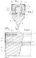
- FIG. 4 is a sectional view along line A-A in FIG. 2.
- Figure 5 is an overview of the support structure for a wiper mounted on the frame of the wiper.
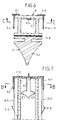
- FIG. 6 is a view of an alternative embodiment of a one-piece assembly of the profile and of the rubber band, in section along the line B-B in FIG. 7.
- FIG. 7 is a sectional view along the line CC of FIG. 6.
- the invention relates to a support structure for a wiper referenced as a whole by (1). It includes a profile (2) made of plastic or other material arranged to receive, hold and guide a rubber band (3) capable of constituting the wiper blade.
- the profile (2) of great length has on one side a U shape forming an internal recess (2.1) with two wings on either side (2.2 - 2.3) between which is engaged in sliding and positioning the upper part forming a bead (3.1) of the strip (3).
- the latter comprises, from its central core (3.2), two longitudinal fins (3.3) arranged in opposition relative to the core and capable of coming to bear against the flanges (2.4) forming edges established at the ends of the wings ( 2.2 - 2.3) of the above-mentioned profile.
- the rubber band extends at its lower part with a triangular flared shape (3.4) capable of being applied to the glass of the windshield.
- the strip (3) on the profile (2) it can be provided at least on one side of their assembly, one, two or three points (4) or more connection by crimping for example.
- the upper (2.5) and outer part of the support (2) is arranged with two longitudinal recesses (2.6), said upper part being capable of allowing the engagement and fixing of retaining and hooking elements (5) able to cooperate with the hooks associated with the support structure of the wiper or its hooks directly.
- the retaining and hooking element (5) thus has two parallel lips (5.1 - 5.2) arranged at the end edge of the retaining element and forming hooks at their end (5.3) and flexible for engaging in the wiper support frame.
- An intermediate lip (5.4) of short length having at the end a triangulated section (5.7), and having a flexibility capacity, and arranged between the lips (5.1 - 5.2), and is capable of penetrating into the U-shaped recess (2.1 ) of the profile (2), ensuring that it is held and attached to the heel (3.1) of the rubber band.
- the width of this intermediate lip (5.4) is established to allow it to be forced into the recess (2.1) of the profile (2).
- the holding element (5) has at the end a flap (5.5) capable of coming to bear against the transverse face (2.7) of the support (2), while lateral fins (5.6) slide along the recesses (2.6) .
- the support structure of the blade can engage and be fixed without difficulty on the frame of the wiper.
- the profile (2) and the rubber band (3) are made in one piece by co-extrusion.
- the rubber band does not have the upper bead (3.1) and the support surface formed by the fins (3.3) is secured to the flange (2.4) of the profile (2), by welding or other.
- the profile (2) is made of polycarbonate while the strip (3) is made of elastomeric material.
- the monobloc assembly (2 - 3) is ready to be cut to the desired length in order to then be fixed to the frame of the wiper.
- the intermediate lip (5.4) enters the recess (2.1) being forcibly engaged as a result of a dimensioning substantially greater than the width of the recess, the ends of the lips coming into abutment against the opposite faces of said recess.
- This assembly is advantageously produced at a standardized length suitable for all types of vehicles. Thus, depending on the length of the wiper, it suffices to cut to length by a suitable cutting tool the aforementioned assembly by a cross section of the element (2) and the strip (3).
- the mounting of the support structure of the wiper according to the invention is extremely easy and its manufacturing cost very low compared to the prior art.
Landscapes
- Engineering & Computer Science (AREA)
- Mechanical Engineering (AREA)
- Cleaning Implements For Floors, Carpets, Furniture, Walls, And The Like (AREA)
- Connection Of Plates (AREA)
Applications Claiming Priority (2)
| Application Number | Priority Date | Filing Date | Title |
|---|---|---|---|
| FR9112933A FR2682341A1 (fr) | 1991-10-11 | 1991-10-11 | Structure support pour essuie-glaces pour vehicules. |
| FR9112933 | 1991-10-11 |
Publications (1)
| Publication Number | Publication Date |
|---|---|
| EP0537093A1 true EP0537093A1 (fr) | 1993-04-14 |
Family
ID=9418117
Family Applications (1)
| Application Number | Title | Priority Date | Filing Date |
|---|---|---|---|
| EP92420358A Withdrawn EP0537093A1 (fr) | 1991-10-11 | 1992-10-09 | Structure-support pour essuie-glaces pour véhicules |
Country Status (2)
| Country | Link |
|---|---|
| EP (1) | EP0537093A1 (OSRAM) |
| FR (1) | FR2682341A1 (OSRAM) |
Cited By (6)
| Publication number | Priority date | Publication date | Assignee | Title |
|---|---|---|---|---|
| FR2708544A1 (fr) * | 1993-07-30 | 1995-02-10 | Bosch Gmbh Robert | Balai d'essuie-glace à palonnier formé de plusieurs éléments. |
| USD372217S (en) | 1993-09-24 | 1996-07-30 | Clean Screen Wipers Pty Ltd | Wiper blade assembly clip |
| USD373563S (en) | 1995-01-12 | 1996-09-10 | Clean Screen Wipers Pty. Ltd. | Extruded wiper backing strip |
| USD377754S (en) | 1995-06-12 | 1997-02-04 | Clean Screen Wipers Pty Ltd | Wiper blade assembly clip |
| US7707681B1 (en) * | 2003-10-14 | 2010-05-04 | Alan Cabak | Windshield wiper clip and bug remover |
| WO2020001776A1 (en) * | 2018-06-28 | 2020-01-02 | Federal-Mogul S.A. | Windscreen wiper device |
Citations (4)
| Publication number | Priority date | Publication date | Assignee | Title |
|---|---|---|---|---|
| DE556851C (de) * | 1929-02-02 | 1932-08-15 | John William Anderson | Windschutzscheibenreiniger |
| US4156951A (en) * | 1977-06-20 | 1979-06-05 | Parker-Hannifin Corporation | Windshield wiper blade unit and fastening clip |
| GB2066655A (en) * | 1979-12-05 | 1981-07-15 | Nu View Pty Ltd | Retention clip |
| WO1991006451A1 (de) * | 1989-11-03 | 1991-05-16 | Robert Bosch Gmbh | Wischblatt |
-
1991
- 1991-10-11 FR FR9112933A patent/FR2682341A1/fr active Granted
-
1992
- 1992-10-09 EP EP92420358A patent/EP0537093A1/fr not_active Withdrawn
Patent Citations (4)
| Publication number | Priority date | Publication date | Assignee | Title |
|---|---|---|---|---|
| DE556851C (de) * | 1929-02-02 | 1932-08-15 | John William Anderson | Windschutzscheibenreiniger |
| US4156951A (en) * | 1977-06-20 | 1979-06-05 | Parker-Hannifin Corporation | Windshield wiper blade unit and fastening clip |
| GB2066655A (en) * | 1979-12-05 | 1981-07-15 | Nu View Pty Ltd | Retention clip |
| WO1991006451A1 (de) * | 1989-11-03 | 1991-05-16 | Robert Bosch Gmbh | Wischblatt |
Cited By (6)
| Publication number | Priority date | Publication date | Assignee | Title |
|---|---|---|---|---|
| FR2708544A1 (fr) * | 1993-07-30 | 1995-02-10 | Bosch Gmbh Robert | Balai d'essuie-glace à palonnier formé de plusieurs éléments. |
| USD372217S (en) | 1993-09-24 | 1996-07-30 | Clean Screen Wipers Pty Ltd | Wiper blade assembly clip |
| USD373563S (en) | 1995-01-12 | 1996-09-10 | Clean Screen Wipers Pty. Ltd. | Extruded wiper backing strip |
| USD377754S (en) | 1995-06-12 | 1997-02-04 | Clean Screen Wipers Pty Ltd | Wiper blade assembly clip |
| US7707681B1 (en) * | 2003-10-14 | 2010-05-04 | Alan Cabak | Windshield wiper clip and bug remover |
| WO2020001776A1 (en) * | 2018-06-28 | 2020-01-02 | Federal-Mogul S.A. | Windscreen wiper device |
Also Published As
| Publication number | Publication date |
|---|---|
| FR2682341B1 (OSRAM) | 1995-02-10 |
| FR2682341A1 (fr) | 1993-04-16 |
Similar Documents
| Publication | Publication Date | Title |
|---|---|---|
| EP0410854B1 (fr) | Déflecteur d'air mobile pour balai d'essuie-glace, notamment de véhicule automobile | |
| BE1018395A5 (fr) | Balai d'essuie-glace. | |
| FR2654691A1 (fr) | Essuie-glace a deflecteur d'air, notamment de vehicule automobile. | |
| FR3048935A1 (fr) | Dispositif d'essuie-glace comportant un adaptateur de bras d'essuie-glace | |
| FR2871127A1 (fr) | Balai d'essuie-glace plat notamment pour vehicule automobile | |
| FR2976880A1 (fr) | Systeme d'essuie-glace | |
| FR2936783A1 (fr) | Dispositif et ensemble de maintien d'une paire de balais d'essuie-glaces,emballage et procede de montage correspondants | |
| WO2014020283A1 (fr) | Systeme de connexion entre un bras d'essuyage et un balai d'essuyage | |
| EP3018017B1 (fr) | Balai d'essuyage de vitres de véhicule automobile | |
| EP0537093A1 (fr) | Structure-support pour essuie-glaces pour véhicules | |
| EP3168093A1 (fr) | Adaptateur pour un essuie-glace de véhicule automobile | |
| FR2744973A1 (fr) | Essuie-glace de vehicule automobile muni d'un capot d'habillage porte par un connecteur d'articulation du balai sur le bras d'essuie-glace | |
| EP0791514B1 (fr) | Essuie-glace de véhicule automobile muni d'un capot d'habillage comportant un tronçon d'extrémité | |
| EP0565443B1 (fr) | Dispositif d'essuie-glace incorporant un déflecteur | |
| FR2755926A1 (fr) | Essuie-glace comportant des moyens perfectionnes d'accrochage d'une raclette d'essuyage | |
| WO2022219097A1 (fr) | Capot pour ensemble d'essuyage pour véhicule automobile | |
| EP2815934B1 (fr) | Balai d'essuie-glace | |
| EP3366531A1 (fr) | Embout d'extremite adaptable pour balai d'essuyage | |
| FR3145908A1 (fr) | lame d’essuyage sans charnière pour balai d’essuie-glace. | |
| EP0728641A1 (fr) | Balai d'essuie-glace comportant une coiffe d'arrêt de la raclette d'essuyage montée sur une griffe de maintien de la raclette | |
| FR2781740A1 (fr) | Essuie-glace de vehicule automobile comportant un deflecteur aerodynamique et raclette d'essuyage pour un tel essuie-glace | |
| FR3058112B1 (fr) | Corps longitudinal pour balai d’essuie-glace et son procede de fabrication | |
| FR3132891A1 (fr) | Balai d’essuyage | |
| FR3093472A1 (fr) | Lécheur de vitre de véhicule automobile | |
| FR3028232A1 (fr) | Balai d’essuyage de vitres de vehicule automobile |
Legal Events
| Date | Code | Title | Description |
|---|---|---|---|
| PUAI | Public reference made under article 153(3) epc to a published international application that has entered the european phase |
Free format text: ORIGINAL CODE: 0009012 |
|
| AK | Designated contracting states |
Kind code of ref document: A1 Designated state(s): BE CH DE ES FR GB IT LI LU NL |
|
| 18D | Application deemed to be withdrawn |
Effective date: 19931015 |