EP0536675A2 - Rayonnage à consoles - Google Patents
Rayonnage à consoles Download PDFInfo
- Publication number
- EP0536675A2 EP0536675A2 EP92116979A EP92116979A EP0536675A2 EP 0536675 A2 EP0536675 A2 EP 0536675A2 EP 92116979 A EP92116979 A EP 92116979A EP 92116979 A EP92116979 A EP 92116979A EP 0536675 A2 EP0536675 A2 EP 0536675A2
- Authority
- EP
- European Patent Office
- Prior art keywords
- hammer head
- cantilever
- stand
- punched
- hammer
- Prior art date
- Legal status (The legal status is an assumption and is not a legal conclusion. Google has not performed a legal analysis and makes no representation as to the accuracy of the status listed.)
- Granted
Links
Images


Classifications
-
- A—HUMAN NECESSITIES
- A47—FURNITURE; DOMESTIC ARTICLES OR APPLIANCES; COFFEE MILLS; SPICE MILLS; SUCTION CLEANERS IN GENERAL
- A47B—TABLES; DESKS; OFFICE FURNITURE; CABINETS; DRAWERS; GENERAL DETAILS OF FURNITURE
- A47B57/00—Cabinets, racks or shelf units, characterised by features for adjusting shelves or partitions
- A47B57/30—Cabinets, racks or shelf units, characterised by features for adjusting shelves or partitions with means for adjusting the height of detachable shelf supports
- A47B57/40—Cabinets, racks or shelf units, characterised by features for adjusting shelves or partitions with means for adjusting the height of detachable shelf supports consisting of hooks coacting with openings
- A47B57/42—Cabinets, racks or shelf units, characterised by features for adjusting shelves or partitions with means for adjusting the height of detachable shelf supports consisting of hooks coacting with openings the shelf supports being cantilever brackets
Definitions
- the invention relates to a cantilever rack for long products such as boards, pipes, profiled iron and the like.
- footplates on the cantilever arms in particular designed as double-T profiles, and extending from them against the uprights and provided for hanging in punched holes provided on the stands and the stands are designed as T-profile stands or as double T-profile stands, in the flanges of which the punched-outs are arranged in pairs at the same height and one above the other.
- a cantilever rack of the same type is known from EP-B1-0 061 514, in which a footplate is fastened to the end of each cantilever arm and two hooks are arranged on each footplate as exclusive holding elements. Even if this known cantilever rack requires little assembly effort when assembling, converting or dismantling, it is perceived as a disadvantage that the cantilever arms are each in one Angle must be pivoted upwards to be able to remove the hooks from the punched holes in the stand. This can result in time-consuming work processes, especially for conversions.
- DE-U-77 11 112 shows a screwless, adjustable heavy-duty cantilever rack, in which the cantilever arms made of stamped and bent sheet metal are suspended from double-T stands.
- side flaps are provided in addition to hooks through punched holes in the stands arranged on the cantilever arms. These side flaps are a hindrance when loading the shelf with long goods and, of all things, reduce the capacity of the cantilever arms at the structurally most favorable stacking point, near the base plates.
- the invention has for its object to provide a cantilever rack that can be assembled and disassembled with as little effort as possible, which can be easily adapted to the spatial conditions of the installation location and the type of goods to be stored and is particularly suitable for heavy-duty loading, and that Possibility of limited adjustment of the angle of inclination of the cantilever arms.
- a cantilever rack of the type mentioned with the invention in that two foot-head screws are assigned as fastening means to each footplate in their upper region in pairs at the same height, the footplate is formed with holes for receiving the threaded ends of the hammer-head screws and in their the lower area is arranged in pairs at the same height with two support feet that can be inserted into a pair of punched-outs, the hammer-head screws with transverse hammer heads reaching behind the punched-out holes of the stand flanges, through which they are initially inserted with vertically positioned heads, after transverse position in the anchor position.
- the load-bearing capacity and thus the safety of the cantilever arms is advantageous in a simple manner significantly increased that the vertical load components are intercepted by the support feet passing through the recesses and thus the hammer head screws are only subjected to tension.
- the hammer head screws can be preassembled in the factory with the foot plates, but then they are not yet fixed non-rotatably, but are arranged in the foot plates with vertically positioned hammer heads and only partially attached nuts.
- the cantilever arm with the support feet is then inserted into a pair of recesses, the hammer head screws also initially protruding vertically through recesses lying above them.
- the hammer heads are then turned into the transverse position, which means that the cantilever is already firmly attached to the stand before the nuts attached to the threaded ends are fully tightened. This advantageously results in a much faster and easier assembly compared to all known screw connections, with considerably reduced workload and increased safety.
- a shoulder with a square cross section is formed on the central shaft area of the hammer head screw between the threaded end and a smooth shaft part carrying the hammer head, which shoulder is in a square recess or recess that is at the front area of each hole in the footplate is formed, is designed to engage and the Keep screw non-rotatable after use in the specified position of the hammer head. This measure also simplifies assembly and increases safety.
- the invention relates to the specially designed and extremely easy-to-assemble, secure and resilient connection between a flange (2) of the stand (1) and a cantilever (4), the fastening means of which in openings or punched-out areas (3) the flanges (2) can be inserted and locked.
- each footplate (7) is formed at its lower area in pairs at the same height with two support feet (8) which can be engaged in a pair of punched-outs (3).
- holes (9) are provided in pairs at the same height for receiving the threaded ends (10) of the hammer head screws (5).
- Fig. 1 From Fig. 1 the particular usefulness of the arrangement according to the invention can be seen, with load forces acting in the vertical direction being supported by the support feet (8) on the lower punching (3), so that the hammer head screws (5) when the cantilever arm (4) is loaded exclusively be loaded in the direction of pull.
- a drop forged part made of high-strength steel in tempered quality such a hammer head screw can transmit tensile stresses, for example, in the order of magnitude of several tons.
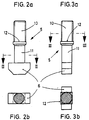
- FIGS. 2a and 3a show the hammer head screw (5) in two different views rotated by 90 ° .
- the cross section of the hammer head screw (5) is shown in section plane II-II according to FIG. 2a and in section plane III-III according to FIG. 3a in FIGS. 2b and 3b.
- This expedient embodiment of the hammer head screws (5) provides that a shoulder (12) with a square cross section is formed on the central shaft area of the hammer head screw (5) between the threaded end (10) and a smooth shaft part (11) carrying the hammer head (6), which is designed to engage in a square recess (13) which is formed on the front region of each bore (9) in the footplate (7) and holds the screw (5) in the non-rotatable position of the hammer head (6).
- the cantilever (4) is already in the workshop pre-assembled hammer head screws (5) can be inserted into the stand (1) without difficulty during assembly, it is provided that the head (6) of the hammer head screws (5) has an essentially rectangular cross section with rounded edges, the dimensions of which correspond to those of a punched-out ( 3) correspond with undersize.
- the head (5) can also deviate from the rectangular shape and, for example, be oval in cross section.
- the cantilever arm (4) then only needs to be inserted into the cutouts (3) with vertically positioned hammer heads (6) and with the support feet (8), after which at least one hammer head (6) is manually transversed, as shown in FIG.
- the rest of the assembly only consists in tightening the nuts (22), preferably with a predetermined torque.
- the nuts (22) are underlaid with a washer and, in some cases, are designed as self-locking nuts.
- An advantageous embodiment of the invention provides that the surface (21) of the footplate (7) facing the stand (1) has side webs (14) which merge with a wedge-shaped rise into a wedge-shaped foot region (15) of the plate (7). This ensures that the base plate (7) is approximately parallel to its surface (20) facing the cantilever arm (4) with the stand (1) and on the stand facing the stand Surface (21) to this at an acute angle (gamma) opening from bottom to top, with the foot region (15) being supported on the stand flange (2).
- this base plate (7) is particularly clear from the combination of FIGS. 4 and 5.
- this base plate (7) can be a cast part made of cast steel or nodular cast iron, so-called spheroidal cast iron, but it can also be produced as a drop-forged part.
- the cantilever arm (4) is welded to the smooth rear surface (20), with high-strength angular seams preferably being carried out on the upper, tensile area.
- the illustration further shows that the comparatively heavy-duty support foot (8) is forged or cast in one piece with the remaining material of the foot plate (7).
- Each support foot (8) protruding from the thickened foot region (15) of the footplate (7), has a support surface projecting approximately at right angles from it (18) and merges into the footplate (7) with a rounded nose section (19) at an obtuse angle (beta).
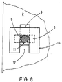
- FIG. 6 it is shown that the shim (16) is designed to be pluggable with a substantially rectangular cutout (17) over the shaft part (11) carrying the hammer head (6). This makes it extremely easy to store the washer (16).
- the invention is surprisingly both uncomplicated and extremely useful.
- the possibility of pre-assembly in the workshop makes it extremely easier to attach the cantilever arms (4) to the stands (1), while doing so with a minimum of work and thus also particularly secure.
- the same advantages also result when converting the cantilever rack, for example when changing the installation location or to adapt to special storage goods.
- the invention optimally fulfills the task set out above.
Landscapes
- Furniture Connections (AREA)
- Joining Of Building Structures In Genera (AREA)
- Display Racks (AREA)
- Warehouses Or Storage Devices (AREA)
- Switches With Compound Operations (AREA)
- Control And Other Processes For Unpacking Of Materials (AREA)
- Inorganic Insulating Materials (AREA)
- Standing Axle, Rod, Or Tube Structures Coupled By Welding, Adhesion, Or Deposition (AREA)
Applications Claiming Priority (2)
| Application Number | Priority Date | Filing Date | Title |
|---|---|---|---|
| DE4133288 | 1991-10-08 | ||
| DE4133288A DE4133288C2 (de) | 1991-10-08 | 1991-10-08 | Kragarmregal |
Publications (3)
| Publication Number | Publication Date |
|---|---|
| EP0536675A2 true EP0536675A2 (fr) | 1993-04-14 |
| EP0536675A3 EP0536675A3 (en) | 1994-10-05 |
| EP0536675B1 EP0536675B1 (fr) | 1996-11-27 |
Family
ID=6442254
Family Applications (1)
| Application Number | Title | Priority Date | Filing Date |
|---|---|---|---|
| EP92116979A Expired - Lifetime EP0536675B1 (fr) | 1991-10-08 | 1992-10-05 | Rayonnage à consoles |
Country Status (6)
| Country | Link |
|---|---|
| EP (1) | EP0536675B1 (fr) |
| AT (1) | ATE145530T1 (fr) |
| DE (2) | DE4133288C2 (fr) |
| DK (1) | DK0536675T3 (fr) |
| ES (1) | ES2095381T3 (fr) |
| GR (1) | GR3022280T3 (fr) |
Families Citing this family (2)
| Publication number | Priority date | Publication date | Assignee | Title |
|---|---|---|---|---|
| DE29604799U1 (de) * | 1996-03-15 | 1996-06-05 | Fiedler, Harald, 63500 Seligenstadt | Kragarmregal |
| DE19852235A1 (de) * | 1998-11-12 | 2000-05-18 | Volkswagen Ag | Kraftstoffförderpumpe mit Staubehälter |
Family Cites Families (9)
| Publication number | Priority date | Publication date | Assignee | Title |
|---|---|---|---|---|
| DE218654C (fr) * | 1906-08-01 | |||
| US1760503A (en) * | 1929-09-03 | 1930-05-27 | Knape & Vogt Mfg Co | Bracket |
| NL112229C (fr) * | 1959-12-04 | |||
| US3512654A (en) * | 1968-05-09 | 1970-05-19 | Jarke Corp | Modular cantilever adjustable arm rack and joint assembly |
| CH602437A5 (fr) * | 1975-06-16 | 1978-07-31 | Fehlbaum & Co | |
| US4700916A (en) * | 1986-06-05 | 1987-10-20 | Hamilton Industries, Inc. | Cantilever arm assembly for modular furniture |
| DE3832537A1 (de) * | 1988-09-24 | 1990-03-29 | Hoelscher Ottokar | Kragarm-regal |
| DE3941386A1 (de) * | 1989-12-15 | 1991-06-20 | Mafisco Bautechnik Gmbh | Kragarm-regal |
| DE9107454U1 (de) * | 1991-06-18 | 1991-09-05 | Hölscher, Ottokar, Dipl.-Ing., 5000 Köln | Kragarmregal |
-
1991
- 1991-10-08 DE DE4133288A patent/DE4133288C2/de not_active Expired - Fee Related
-
1992
- 1992-10-05 AT AT92116979T patent/ATE145530T1/de not_active IP Right Cessation
- 1992-10-05 EP EP92116979A patent/EP0536675B1/fr not_active Expired - Lifetime
- 1992-10-05 ES ES92116979T patent/ES2095381T3/es not_active Expired - Lifetime
- 1992-10-05 DK DK92116979.3T patent/DK0536675T3/da active
- 1992-10-05 DE DE59207587T patent/DE59207587D1/de not_active Expired - Fee Related
-
1997
- 1997-01-15 GR GR970400054T patent/GR3022280T3/el unknown
Also Published As
| Publication number | Publication date |
|---|---|
| DE59207587D1 (de) | 1997-01-09 |
| GR3022280T3 (en) | 1997-04-30 |
| EP0536675B1 (fr) | 1996-11-27 |
| ATE145530T1 (de) | 1996-12-15 |
| ES2095381T3 (es) | 1997-02-16 |
| DE4133288C2 (de) | 1999-07-22 |
| EP0536675A3 (en) | 1994-10-05 |
| DE4133288A1 (de) | 1993-04-15 |
| DK0536675T3 (fr) | 1997-03-17 |
Similar Documents
| Publication | Publication Date | Title |
|---|---|---|
| EP0926967B1 (fr) | Rayonnage a bras en porte-a-faux | |
| EP0418551B1 (fr) | Unité d'étagères ou dispositif de stockage similaire, surtout pour des objets longs | |
| EP0611724A1 (fr) | Dispositif de guidage pour ascenseurs | |
| DE102010006560A1 (de) | Tragvorrichtung und Schalungssystem | |
| DE3831517C2 (fr) | ||
| EP0519316B1 (fr) | Rayonnage à consoles | |
| EP0337415B1 (fr) | Elément amortisseur de bruit | |
| EP0536675B1 (fr) | Rayonnage à consoles | |
| DE202017002584U1 (de) | Anordnung zur winkeligen Verbindung zweier Bauteile miteinander, insbesondere für eine Trocken- oder Metallleichtbaukonstruktion | |
| EP1207766B1 (fr) | Rayonnage a bras en porte-a-faux | |
| DE3152360C2 (fr) | ||
| WO1989011813A1 (fr) | Systeme de rayonnage | |
| EP4131683A1 (fr) | Module d'un système de porte-câble | |
| DE102006039569A1 (de) | Verbindungselement | |
| DE2639987C2 (de) | Steckverbindung für Skelettkonstruktionen | |
| EP4145651B1 (fr) | Flèche à appui d'un seul côté d'extrémité pour un système de porte-câble | |
| DE9313213U1 (de) | Kragarmregal | |
| DE9217610U1 (de) | Kragarmregal | |
| DE102021120323B4 (de) | Endseitig einseitig abgestützter Ausleger für ein Kabeltragsystem | |
| DE102022001035B3 (de) | Universal Adapter zur Montage an einem Fixpunkt eines Fahrzeugs | |
| EP0638694B1 (fr) | Ancre de suspension pour profilés en double T | |
| DE102023116787A1 (de) | Einhängeelement für Ankerplatte eines Seitenunfallschutzes, Ankerplatte für Seitenunfallschutz sowie System aus Ankerplatte und Einhängeelement | |
| DE69609173T2 (de) | Regalsystem | |
| DE2416154A1 (de) | Vorrichtung zur befestigung schwerer lasten | |
| DE9400159U1 (de) | Palettenregal |
Legal Events
| Date | Code | Title | Description |
|---|---|---|---|
| PUAI | Public reference made under article 153(3) epc to a published international application that has entered the european phase |
Free format text: ORIGINAL CODE: 0009012 |
|
| PUAL | Search report despatched |
Free format text: ORIGINAL CODE: 0009013 |
|
| PUAF | Information related to the publication of a search report (a3 document) modified or deleted |
Free format text: ORIGINAL CODE: 0009199SEPU |
|
| 17P | Request for examination filed |
Effective date: 19921104 |
|
| AK | Designated contracting states |
Kind code of ref document: A2 Designated state(s): AT BE CH DE DK ES FR GB GR IE IT LI LU MC NL PT SE |
|
| AK | Designated contracting states |
Kind code of ref document: A3 Designated state(s): AT BE CH DE DK ES FR GB GR IE IT LI LU MC NL PT SE |
|
| RAP1 | Party data changed (applicant data changed or rights of an application transferred) |
Owner name: OHRA REGALANLAGEN GMBH |
|
| D17D | Deferred search report published (deleted) | ||
| PUAL | Search report despatched |
Free format text: ORIGINAL CODE: 0009013 |
|
| AK | Designated contracting states |
Kind code of ref document: A3 Designated state(s): AT BE CH DE DK ES FR GB GR IE IT LI LU MC NL PT SE |
|
| GRAG | Despatch of communication of intention to grant |
Free format text: ORIGINAL CODE: EPIDOS AGRA |
|
| GRAH | Despatch of communication of intention to grant a patent |
Free format text: ORIGINAL CODE: EPIDOS IGRA |
|
| 17Q | First examination report despatched |
Effective date: 19960318 |
|
| GRAH | Despatch of communication of intention to grant a patent |
Free format text: ORIGINAL CODE: EPIDOS IGRA |
|
| GRAA | (expected) grant |
Free format text: ORIGINAL CODE: 0009210 |
|
| AK | Designated contracting states |
Kind code of ref document: B1 Designated state(s): AT BE CH DE DK ES FR GB GR IE IT LI LU MC NL PT SE |
|
| REF | Corresponds to: |
Ref document number: 145530 Country of ref document: AT Date of ref document: 19961215 Kind code of ref document: T |
|
| ET | Fr: translation filed | ||
| GBT | Gb: translation of ep patent filed (gb section 77(6)(a)/1977) |
Effective date: 19961127 |
|
| REG | Reference to a national code |
Ref country code: IE Ref legal event code: FG4D Free format text: 70762 |
|
| REF | Corresponds to: |
Ref document number: 59207587 Country of ref document: DE Date of ref document: 19970109 |
|
| ITF | It: translation for a ep patent filed | ||
| REG | Reference to a national code |
Ref country code: ES Ref legal event code: FG2A Ref document number: 2095381 Country of ref document: ES Kind code of ref document: T3 |
|
| REG | Reference to a national code |
Ref country code: DK Ref legal event code: T3 |
|
| REG | Reference to a national code |
Ref country code: GR Ref legal event code: FG4A Free format text: 3022280 |
|
| REG | Reference to a national code |
Ref country code: PT Ref legal event code: SC4A Free format text: AVAILABILITY OF NATIONAL TRANSLATION Effective date: 19970218 |
|
| PLBE | No opposition filed within time limit |
Free format text: ORIGINAL CODE: 0009261 |
|
| 26N | No opposition filed | ||
| REG | Reference to a national code |
Ref country code: GB Ref legal event code: IF02 |
|
| PGFP | Annual fee paid to national office [announced via postgrant information from national office to epo] |
Ref country code: GR Payment date: 20020822 Year of fee payment: 11 |
|
| PGFP | Annual fee paid to national office [announced via postgrant information from national office to epo] |
Ref country code: IE Payment date: 20020826 Year of fee payment: 11 |
|
| PGFP | Annual fee paid to national office [announced via postgrant information from national office to epo] |
Ref country code: PT Payment date: 20020904 Year of fee payment: 11 |
|
| PGFP | Annual fee paid to national office [announced via postgrant information from national office to epo] |
Ref country code: GB Payment date: 20020913 Year of fee payment: 11 |
|
| PGFP | Annual fee paid to national office [announced via postgrant information from national office to epo] |
Ref country code: NL Payment date: 20021017 Year of fee payment: 11 Ref country code: FR Payment date: 20021017 Year of fee payment: 11 |
|
| PGFP | Annual fee paid to national office [announced via postgrant information from national office to epo] |
Ref country code: MC Payment date: 20021021 Year of fee payment: 11 |
|
| PGFP | Annual fee paid to national office [announced via postgrant information from national office to epo] |
Ref country code: DK Payment date: 20021022 Year of fee payment: 11 Ref country code: AT Payment date: 20021022 Year of fee payment: 11 |
|
| PGFP | Annual fee paid to national office [announced via postgrant information from national office to epo] |
Ref country code: SE Payment date: 20021023 Year of fee payment: 11 Ref country code: LU Payment date: 20021023 Year of fee payment: 11 Ref country code: CH Payment date: 20021023 Year of fee payment: 11 Ref country code: BE Payment date: 20021023 Year of fee payment: 11 |
|
| PGFP | Annual fee paid to national office [announced via postgrant information from national office to epo] |
Ref country code: ES Payment date: 20021024 Year of fee payment: 11 |
|
| PGFP | Annual fee paid to national office [announced via postgrant information from national office to epo] |
Ref country code: DE Payment date: 20030812 Year of fee payment: 12 |
|
| PG25 | Lapsed in a contracting state [announced via postgrant information from national office to epo] |
Ref country code: LU Free format text: LAPSE BECAUSE OF NON-PAYMENT OF DUE FEES Effective date: 20031005 Ref country code: GB Free format text: LAPSE BECAUSE OF NON-PAYMENT OF DUE FEES Effective date: 20031005 Ref country code: AT Free format text: LAPSE BECAUSE OF NON-PAYMENT OF DUE FEES Effective date: 20031005 |
|
| PG25 | Lapsed in a contracting state [announced via postgrant information from national office to epo] |
Ref country code: SE Free format text: LAPSE BECAUSE OF NON-PAYMENT OF DUE FEES Effective date: 20031006 Ref country code: IE Free format text: LAPSE BECAUSE OF NON-PAYMENT OF DUE FEES Effective date: 20031006 Ref country code: ES Free format text: LAPSE BECAUSE OF NON-PAYMENT OF DUE FEES Effective date: 20031006 |
|
| PG25 | Lapsed in a contracting state [announced via postgrant information from national office to epo] |
Ref country code: MC Free format text: LAPSE BECAUSE OF NON-PAYMENT OF DUE FEES Effective date: 20031031 Ref country code: LI Free format text: LAPSE BECAUSE OF NON-PAYMENT OF DUE FEES Effective date: 20031031 Ref country code: CH Free format text: LAPSE BECAUSE OF NON-PAYMENT OF DUE FEES Effective date: 20031031 Ref country code: BE Free format text: LAPSE BECAUSE OF NON-PAYMENT OF DUE FEES Effective date: 20031031 |
|
| BERE | Be: lapsed |
Owner name: *OHRA REGALANLAGEN G.M.B.H. Effective date: 20031031 |
|
| PG25 | Lapsed in a contracting state [announced via postgrant information from national office to epo] |
Ref country code: PT Free format text: LAPSE BECAUSE OF NON-PAYMENT OF DUE FEES Effective date: 20040430 Ref country code: DK Free format text: LAPSE BECAUSE OF NON-PAYMENT OF DUE FEES Effective date: 20040430 |
|
| PG25 | Lapsed in a contracting state [announced via postgrant information from national office to epo] |
Ref country code: NL Free format text: LAPSE BECAUSE OF NON-PAYMENT OF DUE FEES Effective date: 20040501 |
|
| PG25 | Lapsed in a contracting state [announced via postgrant information from national office to epo] |
Ref country code: GR Free format text: LAPSE BECAUSE OF NON-PAYMENT OF DUE FEES Effective date: 20040504 |
|
| GBPC | Gb: european patent ceased through non-payment of renewal fee |
Effective date: 20031005 |
|
| EUG | Se: european patent has lapsed | ||
| REG | Reference to a national code |
Ref country code: DK Ref legal event code: EBP |
|
| REG | Reference to a national code |
Ref country code: CH Ref legal event code: PL |
|
| PG25 | Lapsed in a contracting state [announced via postgrant information from national office to epo] |
Ref country code: FR Free format text: LAPSE BECAUSE OF NON-PAYMENT OF DUE FEES Effective date: 20040630 |
|
| NLV4 | Nl: lapsed or anulled due to non-payment of the annual fee |
Effective date: 20040501 |
|
| REG | Reference to a national code |
Ref country code: IE Ref legal event code: MM4A |
|
| REG | Reference to a national code |
Ref country code: FR Ref legal event code: ST Ref country code: PT Ref legal event code: MM4A Free format text: LAPSE DUE TO NON-PAYMENT OF FEES Effective date: 20040430 |
|
| REG | Reference to a national code |
Ref country code: ES Ref legal event code: FD2A Effective date: 20031006 |
|
| PG25 | Lapsed in a contracting state [announced via postgrant information from national office to epo] |
Ref country code: DE Free format text: LAPSE BECAUSE OF NON-PAYMENT OF DUE FEES Effective date: 20050503 |
|
| PG25 | Lapsed in a contracting state [announced via postgrant information from national office to epo] |
Ref country code: IT Free format text: LAPSE BECAUSE OF NON-PAYMENT OF DUE FEES;WARNING: LAPSES OF ITALIAN PATENTS WITH EFFECTIVE DATE BEFORE 2007 MAY HAVE OCCURRED AT ANY TIME BEFORE 2007. THE CORRECT EFFECTIVE DATE MAY BE DIFFERENT FROM THE ONE RECORDED. Effective date: 20051005 |