EP0536090A2 - Vorrichtung zum In- und Ausserbetriebsetzen von Nadel- und Vorlochnadelstangen für eine Stickmaschine - Google Patents
Vorrichtung zum In- und Ausserbetriebsetzen von Nadel- und Vorlochnadelstangen für eine Stickmaschine Download PDFInfo
- Publication number
- EP0536090A2 EP0536090A2 EP92830510A EP92830510A EP0536090A2 EP 0536090 A2 EP0536090 A2 EP 0536090A2 EP 92830510 A EP92830510 A EP 92830510A EP 92830510 A EP92830510 A EP 92830510A EP 0536090 A2 EP0536090 A2 EP 0536090A2
- Authority
- EP
- European Patent Office
- Prior art keywords
- bars
- lever
- slider
- bar
- disengagement
- Prior art date
- Legal status (The legal status is an assumption and is not a legal conclusion. Google has not performed a legal analysis and makes no representation as to the accuracy of the status listed.)
- Granted
Links
Images


Classifications
-
- D—TEXTILES; PAPER
- D05—SEWING; EMBROIDERING; TUFTING
- D05C—EMBROIDERING; TUFTING
- D05C11/00—Devices for guiding, feeding, handling, or treating the threads in embroidering machines; Machine needles; Operating or control mechanisms therefor
- D05C11/16—Arrangements for repeating thread patterns or for changing threads
Definitions
- the present invention relates to a device for enabling and disabling the needle bars and the piercer bars according to a predetermined program in an embroidery machine and particularly it offers improvements with respect to both the restaurant patent Nr. 1.153.643 filed on November 5, 1992 and the European Patent Application Nr. 0230.211 filed on June 6, 1986, the two both by the applicant of the present patent application.
- the device forming the object of the present invention comprises a series of needle bars suitable to be enabled and disabled according to a certain program with the same arrangement of the structure described in the above cited facility patent, but representing an improvement thereof as in the present invention piercer bars are also provided having means for enabling and disabling the bars themselves indipendently from the means for enabling and disabling the needle bars.
- the present invention represents an improvement also with respect to the above cited European Patent Application as, while in the latter two different operating means are provided for enabling and disabling the needle bars and the piercer bars, in the present invention a single operating means is advantageously provided for enabling and disabling the needles and the piercers.
- an oscillating drive bar 1 according to the prior art relative to the embroidery machines, shifts to and fro on a horizontal plan according to the double arrow X.
- Said bar 1 is connected to either the needle bars 2 or the piercer bars 3 through connecting means to be described hereinafter.
- the drawings show only one needle bar and a corresponding piercer bar, both said bars being a part of a so called rapport, even if such machines comprise a plurality of needle bars and the same number of piercer bars.
- Said connecting means consists of two hooks 4 and 5, respectively for a needle bar 2 and for a piercer bar 3.
- a slider 6 is fixed on the needle bar 2 and surrounds the stationary shaft 7 while a slider 8 is fixed on the corresponding piercer bar 3.
- the hooks 4 and 5 are pivoted respectively through pins 9 and 10 around which small springs 11 and 12 are wound tending to cause the downward rotation of said hooks 4 and 5, as wholly shown in fig. 3.
- a body 13 is fixed, while being provided with holes through which the needle bars 2 or the piercer bars 3 slide, when these are alternatively connected to the oscillating drive bar 1.
- a cap 15 is fixed, by means of screws, below which an actuating member 16 can be moved, e.g. through a pneumatic piston not shown in the drawing, while being provided with slots 17 in which pawls 18 having projections 19 and 19' are inserted.
- one pawl is provided for each rapport consisting of a needle bar 2 and a corresponding piercer bar 3, and that the actuating member 16 is one and only for the whole machine and it can be shifted in two positions corresponding to the tiltings of the pawls according to the axes a and b , as shown in Fig.4.
- two small blocks 20 and 21 are placed, in turn respectively above the hooks 4 and 5.
- the single drive bar 16 causes, in one position, the enabling of all the needle bars and the disabling of all the piercer bars and, in the other position, it causes the enabling of all the piercer bars and the disabling of all the needle bars.
- a slider 22 is provided, combined with each pair of small blocks 20 and 21, having its upper part inserted between the two small blocks 20,21 and actuated in its lower part by a resetting bar 23 which is moved both upwards and downwards, e.g. by means of a pneumatic piston not represented in the drawing.
- Said resetting bar 23 is connected to the various sliders 22 by an elastic member 24.
- two springs 25 are provided for each small block 20,21; such springs tend to push upwards the slider and the small blocks of each rapport.
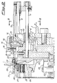
- a selecting lever 26 is provided which is pivoted at 26' and keeping lowered, in the position of Fig.2, both the corresponding sliders 22 and the small blocks 20,21 as well as keeping raised the hooks 4 and 5 which thus result disengaged from the oscillating drive bar 1.
- Such a position of the selecting levers 26 is obtained by lowering the resetting bar 23 thus causing the slider 22 to lower from the position represented in dashed line to the one represented in unbroken line of the upper end of the slider itself, so that said selecting levers 26 are pushed by the springs 27 in said position of disengagement.
- the selecting levers 26 are provided with a projection 28 as well as the sliders 22 are provided with a projection 29 so that when the sliders 22 lower, by means of the resetting bar 23, from the position represented in unbroken line in Fig.2, the selecting levers 26 move to the position represented in dashed line in the same drawing and are held by magnets 30, if excited, each of them being placed in correspondence with a selecting lever 26.
- there are both excited magnets 30 and non-excited others so that the excited ones hold the corresponding selecting levers 26, while the non-excited ones allow the corresponding selecting levers 26 to return, as being pushed by the corresponding springs 27, in the position of disengagement.
- the oscillating bar 1 depending on the presetting thereof to cause the operation of either the needle bars or the piercer bars, moves according to motion laws different from each other and proper for each of these movements which are selectable upstream of the above described device.
- the hooks 4 and 5 have an internal outline, which reaches the oscillating drive bar 1, shaped according to a plane, whereby it slides along the protruding part of said bar 1 without any wear of the touching parts.
- a rod 31 is fixed which passes through a narrow opening 32, acting as a pivot, obtained in a hub 33.
- the rod 31 is pivoted at 34 on a middle lever 35 which is the counterpart of a roller supporting lever 36 in turn pivoted at 37 inside said lever 35.
- a roller 36' on which the yarn feeding each needle bar is wound, is freely rotatable around a pin 38 of the lever 36 and is integral with a gear 39 which in turn engages with another gear 40 on whose axis a braking means is mounted, not shown in the drawing, common to all the needle bars.
- the middle lever 35 thereby rotating upwards, pulls with its edge 41 the roller supporting lever 36 so that the gear 39 moves thus disengaging from the gear 40.
- the yarn winding roller 36' stops, thereby interrupting the yarn feeding to the disengaged needle bar 2, which corresponds to said lever 26 in the position of disengagement.
- an upward releasing of the sliders 22, which corresponds to an enabling of the needle bars, involves an anticlockwise rotation of the middle lever 35 on the pivot 37, this being caused by the lowering of the pivot 34 and the consequent coupling of the gears 39 and 40.
- the above described mechanism allows a manual free rotation of the roller supporting lever 36 on the pivot 37 from a position I to a position II in order to facilitate the threading of the yarn in the machine.
- the edge 42 of the lever 36 touches the corner 43 of the middle lever 35 thus causing a clockwise rotation of the middle lever 35 itself on the pivot 37 with a consequent upward shifting of the pivot 34 and disengagement of the corresponding needle bar by means of the slider 22 which, being pushed by the end of the rod 31 opposite to the pivot 34, reaches the position of disengagement.
- a subsequent manual enabling of the needle bar occurs by manually operating the selecting lever 26, thus causing it to reach the enabling position in which it touches the corresponding magnet.
- the advantages of this invention are the following: improved simplicity and savings both in the realization and operation thereof, mainly due to the fact that the needle bars and the piercer bars are actuated by a single means, and to the fact that the actuating means of the selecting levers, e.g. consisting of magnets, are stationary and each of them for one selecting lever.
Landscapes
- Engineering & Computer Science (AREA)
- Textile Engineering (AREA)
- Sewing Machines And Sewing (AREA)
- Automatic Embroidering For Embroidered Or Tufted Products (AREA)
Applications Claiming Priority (2)
| Application Number | Priority Date | Filing Date | Title |
|---|---|---|---|
| ITMI912526 | 1991-09-23 | ||
| ITMI912526A IT1251850B (it) | 1991-09-23 | 1991-09-23 | Dispositivo per l'innesto e il disinnesto delle barre degli aghi e delle barre dei perforatori in una macchina ricamatrice |
Publications (3)
| Publication Number | Publication Date |
|---|---|
| EP0536090A2 true EP0536090A2 (de) | 1993-04-07 |
| EP0536090A3 EP0536090A3 (de) | 1993-05-12 |
| EP0536090B1 EP0536090B1 (de) | 1996-05-29 |
Family
ID=11360741
Family Applications (1)
| Application Number | Title | Priority Date | Filing Date |
|---|---|---|---|
| EP92830510A Expired - Lifetime EP0536090B1 (de) | 1991-09-23 | 1992-09-22 | Vorrichtung zum In- und Ausserbetriebsetzen von Nadel- und Vorlochnadelstangen für eine Stickmaschine |
Country Status (5)
| Country | Link |
|---|---|
| EP (1) | EP0536090B1 (de) |
| JP (1) | JPH05195409A (de) |
| AT (1) | ATE138700T1 (de) |
| DE (1) | DE69211085T2 (de) |
| IT (1) | IT1251850B (de) |
Family Cites Families (5)
| Publication number | Priority date | Publication date | Assignee | Title |
|---|---|---|---|---|
| DE2541359C2 (de) * | 1975-09-17 | 1984-02-02 | Maschinenfabrik Carl Zangs Ag, 4150 Krefeld | Stickmaschine |
| IT1062146B (it) * | 1976-07-28 | 1983-06-25 | Comerio Ercole Spa | Perfezionamenti relativi ad una macchina ricamatrice a telaio tipo plauen o simili |
| AT395728B (de) * | 1982-03-29 | 1993-02-25 | August Heinzle | Schiffchenstickmaschine |
| CH662140A5 (de) * | 1983-10-06 | 1987-09-15 | Saurer Ag Adolph | Stickmaschine. |
| IT1188284B (it) * | 1986-01-21 | 1988-01-07 | Comercio Ercole Spa | Dispositivo per l'attivazione e disattivazione di barre porta-ago e barre porta-perforatore secondo un programma preimpostabile,particolarmente in una macchina ricamatrice a navetta |
-
1991
- 1991-09-23 IT ITMI912526A patent/IT1251850B/it active IP Right Grant
-
1992
- 1992-09-22 JP JP4253253A patent/JPH05195409A/ja active Pending
- 1992-09-22 DE DE69211085T patent/DE69211085T2/de not_active Expired - Fee Related
- 1992-09-22 EP EP92830510A patent/EP0536090B1/de not_active Expired - Lifetime
- 1992-09-22 AT AT92830510T patent/ATE138700T1/de not_active IP Right Cessation
Also Published As
| Publication number | Publication date |
|---|---|
| EP0536090A3 (de) | 1993-05-12 |
| EP0536090B1 (de) | 1996-05-29 |
| ITMI912526A0 (it) | 1991-09-23 |
| JPH05195409A (ja) | 1993-08-03 |
| DE69211085T2 (de) | 1996-10-02 |
| ITMI912526A1 (it) | 1993-03-23 |
| ATE138700T1 (de) | 1996-06-15 |
| DE69211085D1 (de) | 1996-07-04 |
| IT1251850B (it) | 1995-05-26 |
Similar Documents
| Publication | Publication Date | Title |
|---|---|---|
| US4254721A (en) | Device for the intermittent interruption of the embroidery needle movement on embroidery- or sewing machines | |
| JP3906085B2 (ja) | ミシン及び自動縫いミシン | |
| US4848253A (en) | Embroidery machine for sewing spangles on fabrics | |
| GB2041990A (en) | Electromagnetic jacquard attachment | |
| EP0536090B1 (de) | Vorrichtung zum In- und Ausserbetriebsetzen von Nadel- und Vorlochnadelstangen für eine Stickmaschine | |
| JP3897641B2 (ja) | ミシン | |
| US4111007A (en) | Yarn changing device in a flat-bed knitting machine | |
| US4063525A (en) | Automatic zigzag sewing machine | |
| US4799628A (en) | Level winder for double-bearing fishing reel | |
| US5212968A (en) | Presser controller of a carriage in a flat knitting machine | |
| US4326563A (en) | Control for a dobby mechanism | |
| US4437423A (en) | Thread trimming device for a sewing machine | |
| US3012424A (en) | Lock for a knitting machine | |
| JPS5933697B2 (ja) | ドビ−機における読取装置 | |
| EP1524347B1 (de) | Rundstrickmaschine für Intarsien-Gestrickstücke | |
| US5138850A (en) | Spring biased pattern bars having electromagnetic selectors | |
| JPS6234857B2 (de) | ||
| TWI839698B (zh) | 縫紉機的穿線裝置及具備該裝置的縫紉機 | |
| PL182249B1 (pl) | Urzadzenie sterujace wyborem funkcji przesuwnych widelek maszyny koronkarskiej PL | |
| JPH0333816B2 (de) | ||
| JPH0135719Y2 (de) | ||
| JPH06319889A (ja) | 多頭ミシンの駆動力解除装置 | |
| JPH0516232Y2 (de) | ||
| US2065922A (en) | Carrier rod operating mechanism | |
| CH642469A5 (de) | Rueckstelleinrichtung fuer zaehlwerke. |
Legal Events
| Date | Code | Title | Description |
|---|---|---|---|
| PUAI | Public reference made under article 153(3) epc to a published international application that has entered the european phase |
Free format text: ORIGINAL CODE: 0009012 |
|
| PUAL | Search report despatched |
Free format text: ORIGINAL CODE: 0009013 |
|
| AK | Designated contracting states |
Kind code of ref document: A2 Designated state(s): AT CH DE LI |
|
| AK | Designated contracting states |
Kind code of ref document: A3 Designated state(s): AT CH DE LI |
|
| 17P | Request for examination filed |
Effective date: 19930616 |
|
| 17Q | First examination report despatched |
Effective date: 19950601 |
|
| GRAA | (expected) grant |
Free format text: ORIGINAL CODE: 0009210 |
|
| AK | Designated contracting states |
Kind code of ref document: B1 Designated state(s): AT CH DE LI |
|
| REF | Corresponds to: |
Ref document number: 138700 Country of ref document: AT Date of ref document: 19960615 Kind code of ref document: T |
|
| REG | Reference to a national code |
Ref country code: CH Ref legal event code: NV Representative=s name: ABATRON-PATENTBUERO AG |
|
| REF | Corresponds to: |
Ref document number: 69211085 Country of ref document: DE Date of ref document: 19960704 |
|
| PLBE | No opposition filed within time limit |
Free format text: ORIGINAL CODE: 0009261 |
|
| 26N | No opposition filed | ||
| PGFP | Annual fee paid to national office [announced via postgrant information from national office to epo] |
Ref country code: CH Payment date: 19980918 Year of fee payment: 7 |
|
| PGFP | Annual fee paid to national office [announced via postgrant information from national office to epo] |
Ref country code: AT Payment date: 19980925 Year of fee payment: 7 |
|
| PGFP | Annual fee paid to national office [announced via postgrant information from national office to epo] |
Ref country code: DE Payment date: 19981123 Year of fee payment: 7 |
|
| PG25 | Lapsed in a contracting state [announced via postgrant information from national office to epo] |
Ref country code: AT Free format text: LAPSE BECAUSE OF NON-PAYMENT OF DUE FEES Effective date: 19990922 |
|
| PG25 | Lapsed in a contracting state [announced via postgrant information from national office to epo] |
Ref country code: LI Free format text: LAPSE BECAUSE OF NON-PAYMENT OF DUE FEES Effective date: 19990930 Ref country code: CH Free format text: LAPSE BECAUSE OF NON-PAYMENT OF DUE FEES Effective date: 19990930 |
|
| REG | Reference to a national code |
Ref country code: CH Ref legal event code: PL |
|
| PG25 | Lapsed in a contracting state [announced via postgrant information from national office to epo] |
Ref country code: DE Free format text: LAPSE BECAUSE OF NON-PAYMENT OF DUE FEES Effective date: 20000701 |