EP0533554B1 - Combined heat exchanger for heating and hot water production with seamless coil for the sanitary water heating - Google Patents
Combined heat exchanger for heating and hot water production with seamless coil for the sanitary water heating Download PDFInfo
- Publication number
- EP0533554B1 EP0533554B1 EP92402523A EP92402523A EP0533554B1 EP 0533554 B1 EP0533554 B1 EP 0533554B1 EP 92402523 A EP92402523 A EP 92402523A EP 92402523 A EP92402523 A EP 92402523A EP 0533554 B1 EP0533554 B1 EP 0533554B1
- Authority
- EP
- European Patent Office
- Prior art keywords
- tubes
- heating
- sanitary
- circuit
- water circuit
- Prior art date
- Legal status (The legal status is an assumption and is not a legal conclusion. Google has not performed a legal analysis and makes no representation as to the accuracy of the status listed.)
- Expired - Lifetime
Links
- 238000010438 heat treatment Methods 0.000 title claims abstract description 41
- XLYOFNOQVPJJNP-UHFFFAOYSA-N water Substances O XLYOFNOQVPJJNP-UHFFFAOYSA-N 0.000 title claims abstract description 38
- 238000004519 manufacturing process Methods 0.000 title abstract description 3
- 238000009434 installation Methods 0.000 claims abstract description 13
- 239000008236 heating water Substances 0.000 claims abstract description 12
- 238000005452 bending Methods 0.000 claims abstract description 7
- 238000003466 welding Methods 0.000 claims abstract 2
- 239000007789 gas Substances 0.000 claims description 6
- 229920003023 plastic Polymers 0.000 claims description 3
- 239000004033 plastic Substances 0.000 claims description 3
- 238000005476 soldering Methods 0.000 claims description 3
- 239000000463 material Substances 0.000 claims description 2
- 238000005192 partition Methods 0.000 claims description 2
- 229920001296 polysiloxane Polymers 0.000 claims description 2
- WYTGDNHDOZPMIW-RCBQFDQVSA-N alstonine Natural products C1=CC2=C3C=CC=CC3=NC2=C2N1C[C@H]1[C@H](C)OC=C(C(=O)OC)[C@H]1C2 WYTGDNHDOZPMIW-RCBQFDQVSA-N 0.000 description 4
- QEVHRUUCFGRFIF-MDEJGZGSSA-N reserpine Chemical compound O([C@H]1[C@@H]([C@H]([C@H]2C[C@@H]3C4=C(C5=CC=C(OC)C=C5N4)CCN3C[C@H]2C1)C(=O)OC)OC)C(=O)C1=CC(OC)=C(OC)C(OC)=C1 QEVHRUUCFGRFIF-MDEJGZGSSA-N 0.000 description 4
- 239000000470 constituent Substances 0.000 description 2
- 208000031968 Cadaver Diseases 0.000 description 1
- RYGMFSIKBFXOCR-UHFFFAOYSA-N Copper Chemical compound [Cu] RYGMFSIKBFXOCR-UHFFFAOYSA-N 0.000 description 1
- 238000000429 assembly Methods 0.000 description 1
- 229910052802 copper Inorganic materials 0.000 description 1
- 239000010949 copper Substances 0.000 description 1
- 239000000945 filler Substances 0.000 description 1
- 239000012530 fluid Substances 0.000 description 1
- 239000002184 metal Substances 0.000 description 1
- 229910052751 metal Inorganic materials 0.000 description 1
- 230000000737 periodic effect Effects 0.000 description 1
- 238000007789 sealing Methods 0.000 description 1
- 229910000679 solder Inorganic materials 0.000 description 1
- 239000000126 substance Substances 0.000 description 1
Images


Classifications
-
- F—MECHANICAL ENGINEERING; LIGHTING; HEATING; WEAPONS; BLASTING
- F28—HEAT EXCHANGE IN GENERAL
- F28F—DETAILS OF HEAT-EXCHANGE AND HEAT-TRANSFER APPARATUS, OF GENERAL APPLICATION
- F28F1/00—Tubular elements; Assemblies of tubular elements
- F28F1/02—Tubular elements of cross-section which is non-circular
-
- F—MECHANICAL ENGINEERING; LIGHTING; HEATING; WEAPONS; BLASTING
- F24—HEATING; RANGES; VENTILATING
- F24H—FLUID HEATERS, e.g. WATER OR AIR HEATERS, HAVING HEAT-GENERATING MEANS, e.g. HEAT PUMPS, IN GENERAL
- F24H1/00—Water heaters, e.g. boilers, continuous-flow heaters or water-storage heaters
- F24H1/48—Water heaters for central heating incorporating heaters for domestic water
- F24H1/52—Water heaters for central heating incorporating heaters for domestic water incorporating heat exchangers for domestic water
-
- F—MECHANICAL ENGINEERING; LIGHTING; HEATING; WEAPONS; BLASTING
- F28—HEAT EXCHANGE IN GENERAL
- F28D—HEAT-EXCHANGE APPARATUS, NOT PROVIDED FOR IN ANOTHER SUBCLASS, IN WHICH THE HEAT-EXCHANGE MEDIA DO NOT COME INTO DIRECT CONTACT
- F28D7/00—Heat-exchange apparatus having stationary tubular conduit assemblies for both heat-exchange media, the media being in contact with different sides of a conduit wall
- F28D7/0066—Multi-circuit heat-exchangers, e.g. integrating different heat exchange sections in the same unit or heat-exchangers for more than two fluids
- F28D7/0075—Multi-circuit heat-exchangers, e.g. integrating different heat exchange sections in the same unit or heat-exchangers for more than two fluids with particular circuits for the same heat exchange medium, e.g. with the same heat exchange medium flowing through sections having different heat exchange capacities or for heating or cooling the same heat exchange medium at different temperatures
-
- F—MECHANICAL ENGINEERING; LIGHTING; HEATING; WEAPONS; BLASTING
- F28—HEAT EXCHANGE IN GENERAL
- F28D—HEAT-EXCHANGE APPARATUS, NOT PROVIDED FOR IN ANOTHER SUBCLASS, IN WHICH THE HEAT-EXCHANGE MEDIA DO NOT COME INTO DIRECT CONTACT
- F28D7/00—Heat-exchange apparatus having stationary tubular conduit assemblies for both heat-exchange media, the media being in contact with different sides of a conduit wall
- F28D7/08—Heat-exchange apparatus having stationary tubular conduit assemblies for both heat-exchange media, the media being in contact with different sides of a conduit wall the conduits being otherwise bent, e.g. in a serpentine or zig-zag
- F28D7/082—Heat-exchange apparatus having stationary tubular conduit assemblies for both heat-exchange media, the media being in contact with different sides of a conduit wall the conduits being otherwise bent, e.g. in a serpentine or zig-zag with serpentine or zig-zag configuration
- F28D7/085—Heat-exchange apparatus having stationary tubular conduit assemblies for both heat-exchange media, the media being in contact with different sides of a conduit wall the conduits being otherwise bent, e.g. in a serpentine or zig-zag with serpentine or zig-zag configuration in the form of parallel conduits coupled by bent portions
-
- F—MECHANICAL ENGINEERING; LIGHTING; HEATING; WEAPONS; BLASTING
- F28—HEAT EXCHANGE IN GENERAL
- F28D—HEAT-EXCHANGE APPARATUS, NOT PROVIDED FOR IN ANOTHER SUBCLASS, IN WHICH THE HEAT-EXCHANGE MEDIA DO NOT COME INTO DIRECT CONTACT
- F28D7/00—Heat-exchange apparatus having stationary tubular conduit assemblies for both heat-exchange media, the media being in contact with different sides of a conduit wall
- F28D7/10—Heat-exchange apparatus having stationary tubular conduit assemblies for both heat-exchange media, the media being in contact with different sides of a conduit wall the conduits being arranged one within the other, e.g. concentrically
- F28D7/14—Heat-exchange apparatus having stationary tubular conduit assemblies for both heat-exchange media, the media being in contact with different sides of a conduit wall the conduits being arranged one within the other, e.g. concentrically both tubes being bent
Definitions
- the present invention relates to a central heating installation provided with a hot water circuit for domestic use or sanitary water and comprising a heating device comprising an envelope or ferrule, the lower part of which is provided with a burner, in particular of a gas burner and on which is wound or not a conduit in which the water circulates from the heating circuit, this circuit then crosses a bundle of fins located at the upper part of the envelope on the trajectory of the hot gases escaping from the latter to then be directed to a discharge pipe.
- European patent EP-A-0329508 (priority French patent FR-A-2627266) describes a central heating installation in which the exchanger is mixed. It mainly comprises a set of tubes used for heating domestic water, shaped as a pin or coil which are arranged inside flattened tubes. Said tubes form a block connected by elbows and a set of fins, they constitute the heating water circuit, the sanitary water being heated by said water.
- This configuration ensures that the tubes of the domestic hot water circuit, arranged in a pin or coil in the flat tubes in the heating water circuit are not in contact with them.
- the dimensions of said flattened tubes and of said tubes are chosen so that the volume of water contained between the flattened tubes and the meanders of the hairpin tubes is as small as possible.
- This arrangement requires having at each end brazed or welded end pieces to close off the heating circuit as well as elbows used to connect the respective circuits together.
- the present invention proposes to provide an improved installation which does not have the drawbacks mentioned above.
- Figure 1 is an overall perspective view of the assembly exploded exploding the various constituents of the mixed exchanger A.
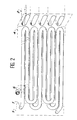
- Figure 2 is a perspective view of the tubes shaped into a series of pins in two perpendicular planes two by two.
- Figure 3 is a plan view of the assembly of the mixed exchanger A.
- Figure 4 is a plan view in side elevation of the mixed exchanger A.
- Figure 5 is a plan view in front elevation during assembly of the mixed exchanger A.
- the heater object of this invention, comprises a first conduit for heating the water of the central heating circuit and a second duct for heating domestic water.
- the duct of the heating circuit is in the form of a series flattened tube pins such as 2 which each have a cross section of oval shape, the largest axis being horizontal.
- These tubes are connected at one of their ends by elbows obtained by bending these said tubes.
- the sanitary water pipe consists of a tube, preferably of circular cross section, placed inside the flattened tubes 2 of the heating circuit, shaped into a series of pins obtained by bending this said tube in two perpendicular planes two by two. This increases the heat exchange surface between the two circuits of the mixed exchanger since all the bends are in the heating circuit and not outside.
- the positioning of the pin-shaped sanitary circuit tubes arranged inside the flattened tubes of the heating circuit is carried out so that there is no physical contact between the walls of the tubes 1 and 2, and so that the volume of water contained in the residual annular space is as small as possible. It also results from this configuration that all the calories conveyed by the heating circuit are transferred into the sanitary water circuit.
- the respective assembly of the constituent sub-assemblies is as follows: the tubes 1 shaped as a hairpin of the sanitary water circuit, provided with plastic rings 6, are inserted inside the flattened tubes 2 of the water circuit of heating, while the fins 3 and the manifold 4 thread on the flattened tubes 2 of the heating circuit, the cover 5 completely closing off the assembly. This collector guarantees the routing of the heating fluid as well as the tightness of the assembly.
- This collector 4 maintains the two circuits of the exchanger. It is brazed on the heating water circuit.
- Reading the above description shows that the invention provides a heating installation ensuring perfect heat exchange between the two incorporated circuits of heating water and sanitary water thanks to a large heat exchange surface obtained by the configuration. the different circuits.
Landscapes
- Engineering & Computer Science (AREA)
- Physics & Mathematics (AREA)
- Thermal Sciences (AREA)
- Mechanical Engineering (AREA)
- General Engineering & Computer Science (AREA)
- Geometry (AREA)
- Chemical & Material Sciences (AREA)
- Combustion & Propulsion (AREA)
- Heat-Exchange Devices With Radiators And Conduit Assemblies (AREA)
- External Artificial Organs (AREA)
Abstract
Description
La présente invention est relative à une installation de chauffage central munie d'un circuit d'eau chaude à usage domestique ou eau sanitaire et comprenant un appareil de chauffage comportant une enveloppe ou virole, dont la partie inférieure est munie d'un brûleur, notamment d'un brûleur à gaz et sur laquelle vient s'enrouler ou non un conduit dans lequel circule l'eau du circuit de chauffage, ce circuit traverse ensuite un faisceau d'ailettes situées à la partie supérieure de l'enveloppe sur la trajectoire des gaz chauds qui s'échappent de cette dernière pour être dirigés ensuite vers une conduite d'évacuation.The present invention relates to a central heating installation provided with a hot water circuit for domestic use or sanitary water and comprising a heating device comprising an envelope or ferrule, the lower part of which is provided with a burner, in particular of a gas burner and on which is wound or not a conduit in which the water circulates from the heating circuit, this circuit then crosses a bundle of fins located at the upper part of the envelope on the trajectory of the hot gases escaping from the latter to then be directed to a discharge pipe.
Le brevet européen EP-A-0329508 (priorité brevet français FR-A-2627266) décrit une installation de chauffage central dans laquelle l'échangeur est mixte. Il comprend principalement un ensemble de tubes servant au chauffage de l'eau sanitaire, conformés en épingle ou serpentin qui sont disposés à l'intérieur de tubes aplatis. Lesdits tubes forment un bloc relié par des coudes et un ensemble d'ailettes, ils constituent le circuit de l'eau de chauffage, l'eau sanitaire étant réchauffée par ladite eau.European patent EP-A-0329508 (priority French patent FR-A-2627266) describes a central heating installation in which the exchanger is mixed. It mainly comprises a set of tubes used for heating domestic water, shaped as a pin or coil which are arranged inside flattened tubes. Said tubes form a block connected by elbows and a set of fins, they constitute the heating water circuit, the sanitary water being heated by said water.
Cette configuration assure que les tubes du circuit d'eau chaude sanitaire, disposés en épingle ou serpentin dans les tubes aplatis du circuit d'eau de chauffage ne sont pas au contact de ces derniers.This configuration ensures that the tubes of the domestic hot water circuit, arranged in a pin or coil in the flat tubes in the heating water circuit are not in contact with them.
Les dimensions desdits tubes aplatis et desdits tubes sont choisies de manière que le volume d'eau contenu entre les tubes aplatis et les méandres des tubes en épingle soit aussi réduit que possible.The dimensions of said flattened tubes and of said tubes are chosen so that the volume of water contained between the flattened tubes and the meanders of the hairpin tubes is as small as possible.
Cette disposition oblige à avoir à chaque extrémité des embouts brasés ou soudés afin d'obturer le circuit de chauffage ainsi que des coudes servant à relier les circuits respectifs entre eux.This arrangement requires having at each end brazed or welded end pieces to close off the heating circuit as well as elbows used to connect the respective circuits together.
Elle présente quelques inconvénients graves, d'une part il est difficile et peu économique de réaliser des soudures ou des brasures étanches, et d'autre part le métal d'apport possède une tenue mécanique et chimique moindre que le cuivre dont sont constitués les tubes. L'espérance de vie de ces échangeurs mixtes s'en trouve réduite en cas de détartrage périodique.It has some serious drawbacks, on the one hand it is difficult and uneconomical to make welds or tight solders, and on the other hand the filler metal has less mechanical and chemical resistance than the copper from which the tubes are made. . The life expectancy of these mixed exchangers is reduced in the event of periodic descaling.
La présente invention se propose d'apporter une installation perfectionnée ne présentant pas les inconvénients mentionnés ci-dessus.The present invention proposes to provide an improved installation which does not have the drawbacks mentioned above.
Elle a donc pour objet une installation de chauffage central munie d'un circuit d'eau chaude à usage domestique ou eau sanitaire qui comprend un appareil de chauffage comportant une virole dont la partie intérieure est munie d'un brûleur ; notamment d'un brûleur à gaz et sur laquelle vient s'enrouler ou non un conduit du circuit de chauffage qui traverse ensuite un faisceau d'ailettes situées à la partie supérieure de la virole, sur le trajet des gaz chauds, le circuit de chauffage dans sa traversée du faisceau d'ailettes étant réalisé sous la forme d'une pluralité de tubes aplatis, raccordés les uns aux autres par des coudes et le circuit d'eau chaude sanitaire étant réalisé sous la forme d'une série de tubes conformés en épingle, reliés entre eux par des coudes, lesdits tubes sanitaires étant disposés à l'intérieur des tubes aplatis concernant le circuit de chauffage, caractérisée en ce que :
- les tubes du serpentin sanitaire possèdent une forme d'épingle, ledit serpentin comporte une portion de tube cintré dans une direction à 90° dans un plan vertical puis une autre à 90° de la précédente et ainsi de suite,
- ledit serpentin comprend une série consécutive de portions de tubes cintrés dans deux plans perpendiculaires et sans soudure,
- la réunion à l'une des extrémités communes de l'ensemble constitué par le circuit d'eau sanitaire conformé en épingle et les tubes aplatis du circuit d'eau de chauffage est réalisée par un collecteur qui est monté sur ces derniers dits tubes ; ce collecteur étant lui-même obturé par un couvercle .
- the tubes of the sanitary coil have a pin shape, said coil comprises a portion of tube bent in a direction at 90 ° in a vertical plane then another at 90 ° from the previous one and so on,
- said coil comprises a consecutive series of portions of tubes bent in two perpendicular and seamless planes,
- the meeting at one of the common ends of the assembly constituted by the sanitary water circuit shaped as a pin and the flattened tubes of the heating water circuit is produced by a collector which is mounted on the latter said tubes; this collector itself being closed by a cover.
D'autres caractéristiques et avantages de cette invention ressortiront de la description faite ci-après en référence aux dessins annexés qui en illustrent des exemples de réalisation dépourvus de tout caractère limitatif.Other characteristics and advantages of this invention will emerge from the description given below with reference to the appended drawings which illustrate exemplary embodiments thereof without any limiting character.
La Figure 1 est une vue en perspective globale de l'ensemble représentant en éclaté les différents constituants de l'échangeur mixte A.Figure 1 is an overall perspective view of the assembly exploded exploding the various constituents of the mixed exchanger A.
La Figure 2 est une vue en perspective des tubes conformés en une série d'épingles dans deux plans perpendiculaires deux à deux.Figure 2 is a perspective view of the tubes shaped into a series of pins in two perpendicular planes two by two.
La Figure 3 est une vue plane de l'ensemble de l'échangeur mixte A.Figure 3 is a plan view of the assembly of the mixed exchanger A.
La Figure 4 est une vue plane en élévation latérale de l'échangeur mixte A.Figure 4 is a plan view in side elevation of the mixed exchanger A.
La Figure 5 est une vue plane en élévation frontale en cours de montage de l'échangeur mixte A.Figure 5 is a plan view in front elevation during assembly of the mixed exchanger A.
Selon un exemple préféré de réalisation de cet échangeur mixte, on dispose, à l'intérieur de ce bloc de tubes aplatis, un ensemble de tubes conformés en épingle, utilisés pour le circuit d'eau chaude sanitaire. L'échangeur mixte est conformé de manière à ce que:
- les dimensions desdits tubes aplatis et desdits tubes du serpentin d'eau sanitaire sont choisies de manière que le volume d'eau compris dans l'espace annulaire entre le corps et les épingles soit aussi réduit que possible;
- le bloc échangeur consiste en une multitude de plaques enfilées et brasées sur les tubes de chauffage aplatis. Ces dits tubes sont reliés à une de leurs extrémités par des coudes élaborés par cintrage de ces dits tubes formant une épingle et sans soudure.
- the dimensions of said flattened tubes and of said tubes of the domestic water coil are chosen so that the volume of water included in the annular space between the body and the pins is as small as possible;
- the heat exchanger block consists of a multitude of plates threaded and brazed onto the flattened heating tubes. These said tubes are connected at one of their ends by elbows produced by bending these said tubes forming a pin and seamless.
En se référant aux dessins et notamment aux Figures 1, 2, 3 et 4, on voit que l'appareil de chauffage, objet de cette invention, comporte un premier conduit pour le chauffage de l'eau du circuit du chauffage central et un second conduit pour le chauffage de l'eau sanitaire.Referring to the drawings and in particular to Figures 1, 2, 3 and 4, it can be seen that the heater, object of this invention, comprises a first conduit for heating the water of the central heating circuit and a second duct for heating domestic water.
On aperçoit (cf Figure 1) le circuit d'eau sanitaire conformé en une série d'épingles 1 inclus à l'intérieur des tubes aplatis 2 du circuit de chauffage, eux aussi conformés en épingle.We can see (see Figure 1) the sanitary water circuit shaped as a series of pins 1 included inside the flattened tubes 2 of the heating circuit, also shaped as pins.
Dans la partie supérieure de l'appareil de chauffage où est positionné l'objet de l'invention, le conduit du circuit de chauffage se présente sous la forme d'une série d'épingles de tubes aplatis tels que 2 qui présentent chacun une section droite de forme ovale, le plus grand axe étant horizontal. Ces tubes sont raccordés à l'une de leurs extrémités par des coudes obtenus par cintrage de ces dits tubes.In the upper part of the heating appliance where the object of the invention is positioned, the duct of the heating circuit is in the form of a series flattened tube pins such as 2 which each have a cross section of oval shape, the largest axis being horizontal. These tubes are connected at one of their ends by elbows obtained by bending these said tubes.
Le conduit d'eau sanitaire est constitué d'un tube, de préférence de section droite circulaire, disposé à l'intérieur des tubes aplatis 2 du circuit de chauffage, conformés en une série d'épingles obtenues par cintrage de ce dit tube dans deux plans perpendiculaires deux à deux. On augmente ainsi la surface d'échange thermique entre les deux circuits de l'échangeur mixte puisque tous les cintrages se trouvent dans le circuit de chauffage et non à l'extérieur.The sanitary water pipe consists of a tube, preferably of circular cross section, placed inside the flattened tubes 2 of the heating circuit, shaped into a series of pins obtained by bending this said tube in two perpendicular planes two by two. This increases the heat exchange surface between the two circuits of the mixed exchanger since all the bends are in the heating circuit and not outside.
Le positionnement des tubes du circuit sanitaire conformés en épingle disposées à l'intérieur des tubes aplatis du circuit de chauffage est réalisé de manière qu'il n'existe aucun contact physique entre les parois des tubes 1 et 2, et de manière que le volume d'eau contenu dans l'espace annulaire résiduel soit le plus petit possible. Il résulte aussi de cette configuration que toutes les calories véhiculées par le circuit de chauffage sont transférées dans le circuit d'eau sanitaire. L'assemblage respectif des sous-ensembles constitutifs est le suivant : les tubes 1 conformés en épingle du circuit d'eau sanitaire, munis des bagues en plastique 6, s'insèrent à l'intérieur des tubes aplatis 2 du circuit d'eau de chauffage, tandis que les ailettes 3 et le collecteur 4 s'enfilent sur les tubes aplatis 2 du circuit de chauffage, le couvercle 5 obturant complètement l'ensemble. Ce collecteur garantit le cheminement du fluide de chauffage ainsi que l'étanchéité de l'ensemble.The positioning of the pin-shaped sanitary circuit tubes arranged inside the flattened tubes of the heating circuit is carried out so that there is no physical contact between the walls of the tubes 1 and 2, and so that the volume of water contained in the residual annular space is as small as possible. It also results from this configuration that all the calories conveyed by the heating circuit are transferred into the sanitary water circuit. The respective assembly of the constituent sub-assemblies is as follows: the tubes 1 shaped as a hairpin of the sanitary water circuit, provided with plastic rings 6, are inserted inside the flattened tubes 2 of the water circuit of heating, while the fins 3 and the manifold 4 thread on the flattened tubes 2 of the heating circuit, the
Ce collecteur 4 assure le maintien des deux circuits de l'échangeur. Il est brasé sur le circuit d'eau de chauffage.This collector 4 maintains the two circuits of the exchanger. It is brazed on the heating water circuit.
Deux cloisons 7 obligent l'eau de chauffage à circuler en série dans les tubes aplatis. Ce collecteur sera lui-même obturé par un couvercle 5 garantissant l'étanchéité.Two partitions 7 force the heating water to circulate in series in the flattened tubes. This collector will itself be closed by a
Dans la variante représentée sur la Figure 3, on peut enfiler sur l'ensemble des tubes du circuit sanitaire des bagues en matière plastique résistant à la chaleur et à l'humidité, de préférence en silicone ; ces bagues étant enfilées sur le tube 1 à intervalles réguliers. Cette disposition particulière présente un double avantage ; elle permet tout d'abord d'éviter tout contact des tubes 1 avec les tubes aplatis 2 constituant le circuit de chauffage, et d'autre part elle élimine les vibrations d'origine hydraulique qui se produisent dans ce type d'installation lorsque l'eau sanitaire circule dans la série d'épingles.In the variant shown in Figure 3, one can thread on all the tubes of the sanitary circuit rings of plastic material resistant to heat and humidity, preferably silicone; these rings being threaded on the tube 1 at regular intervals. This particular arrangement has a double advantage; it first of all makes it possible to avoid any contact of the tubes 1 with the flattened tubes 2 constituting the heating circuit, and on the other hand it eliminates the vibrations of hydraulic origin which occur in this type of installation when the sanitary water circulates in the series of pins.
La lecture de la description qui précède montre que l'invention apporte une installation de chauffage assurant un échange thermique parfait entre les deux circuits incorporés d'eau de chauffage et d'eau sanitaire grâce à une surface d'échange thermique importante obtenue par la configuration en épingle des différents circuits.Reading the above description shows that the invention provides a heating installation ensuring perfect heat exchange between the two incorporated circuits of heating water and sanitary water thanks to a large heat exchange surface obtained by the configuration. the different circuits.
L'absence de coudes rapportés sur chacun des circuits, les changements de direction étant obtenus par cintrage des tubes des différents circuits, simplifie le mode de fabrication de l'échangeur, plus de brasure ni de soudure et évite les risques de fuites.The absence of added bends on each of the circuits, the changes of direction being obtained by bending the tubes of the different circuits, simplifies the method of manufacturing the exchanger, no more soldering or soldering and avoids the risks of leaks.
Claims (6)
- Central heating installation equipped with a hot water circuit for domestic use or sanitary water, which contains a heating apparatus comprising a casing, the internal part of which is equipped with a burner, notably a gas burner, and around which is wound or not a heating circuit pipe which then passes through a bundle of fins situated in the upper part of the casing on the path of the hot gases, the heating circuit, in its passage through the bundle of fins, being realised in the form of a plurality of flattened tubes, connected to one another by elbows, and the sanitary hot water circuit being realised in the form of a series of tubes (1) of hairpin shape connected together by elbows, said sanitary tubes being disposed inside the flattened tubes (2) associated with the heating circuit, characterized in that:- the tubes of the sanitary coil have a hairpin shape, said coil comprises a tube portion bent through 90° in a vertical plane and then another at 90° to the foregoing and so on,- said coil comprises a consecutive series of curved tube portions in two mutually perpendicular planes without welding or soldering,- the connection to one of the common ends of the assembly constituted of the hairpin-shaped sanitary water circuit and the flattened tubes (2) of the heating water circuit is realised by a header (4) which is mounted on the latter said tubes (2), this header being itself closed by a cover (5).
- Heating installation according to claim 1, characterized in that the header (4) is equipped with partitions (7) compelling the heating water to circulate in series through the flattened tubes.
- Heating installation according to one of claims 1 or 2, characterized in that the tubes (1) of the sanitary hot water circuit, disposed in a series of hairpins in the flattened tubes (2) of the heating water circuit, are not in contact with the latter.
- Heating installation according to any one of claims 1 to 3, characterized in that the dimensions of said flattened tubes (2) and of said tubes (1) of the sanitary water circuit are so chosen that the volume of water contained in the annular space between the flattened tubes and the hairpin tubes shall be as small as possible.
- Heating installation according to any one of claims 1 to 4, characterized in that the hairpin-shape flattened tubes (2) of the heating water circuit are connected by elbows produced by bending said tubes two by two in two perpendicular planes.
- Heating installation according to any one of the preceding claims, characterized in that the tubes (1) of the sanitary water circuit, arranged in hairpin shape in the flattened tubes (2) of the heating water circuit are equipped with a plurality of rings (6) of heat-resistant and humidity-resistant plastics material such as, for example, of silicone, these rings being threaded on to the tube at regular intervals.
Applications Claiming Priority (2)
| Application Number | Priority Date | Filing Date | Title |
|---|---|---|---|
| FR9111556 | 1991-09-19 | ||
| FR9111556A FR2667399A1 (en) | 1990-09-19 | 1991-09-19 | METHOD AND APPARATUS FOR MONITORING, IN PARTICULAR FOR CONTAINERS. |
Publications (2)
| Publication Number | Publication Date |
|---|---|
| EP0533554A1 EP0533554A1 (en) | 1993-03-24 |
| EP0533554B1 true EP0533554B1 (en) | 1995-01-18 |
Family
ID=9417101
Family Applications (1)
| Application Number | Title | Priority Date | Filing Date |
|---|---|---|---|
| EP92402523A Expired - Lifetime EP0533554B1 (en) | 1991-09-19 | 1992-09-15 | Combined heat exchanger for heating and hot water production with seamless coil for the sanitary water heating |
Country Status (4)
| Country | Link |
|---|---|
| EP (1) | EP0533554B1 (en) |
| AT (1) | ATE117425T1 (en) |
| DE (1) | DE69201226T2 (en) |
| ES (1) | ES2066582T3 (en) |
Family Cites Families (3)
| Publication number | Priority date | Publication date | Assignee | Title |
|---|---|---|---|---|
| DE2742820C2 (en) * | 1977-09-23 | 1985-09-12 | Robert Bosch Gmbh, 7000 Stuttgart | Heat exchanger for a gas or oil heated instant water heater |
| IT1167106B (en) * | 1983-01-11 | 1987-05-13 | Luciano Tesolin | COAXIAL WATER PIPE EXCHANGER WITH SPIROID GEOMETRY, FOR HEATING AND HOT WATER PRODUCTION BOILERS, FOR ASPIRED AIR GAS BURNERS |
| FR2627266B1 (en) * | 1988-02-16 | 1990-06-01 | Leblanc Sa E L M | CENTRAL HEATING SYSTEM WITH HOT WATER CIRCUIT FOR SANITARY USE |
-
1992
- 1992-09-15 EP EP92402523A patent/EP0533554B1/en not_active Expired - Lifetime
- 1992-09-15 ES ES92402523T patent/ES2066582T3/en not_active Expired - Lifetime
- 1992-09-15 AT AT92402523T patent/ATE117425T1/en not_active IP Right Cessation
- 1992-09-15 DE DE69201226T patent/DE69201226T2/en not_active Expired - Fee Related
Also Published As
| Publication number | Publication date |
|---|---|
| DE69201226T2 (en) | 1995-05-24 |
| ATE117425T1 (en) | 1995-02-15 |
| ES2066582T3 (en) | 1995-03-01 |
| EP0533554A1 (en) | 1993-03-24 |
| DE69201226D1 (en) | 1995-03-02 |
Similar Documents
| Publication | Publication Date | Title |
|---|---|---|
| KR20050021546A (en) | Heat exchanger | |
| EP0533554B1 (en) | Combined heat exchanger for heating and hot water production with seamless coil for the sanitary water heating | |
| FR2681670A1 (en) | Heating/hot-water hybrid exchanger, with a weldless domestic-water heating coil | |
| EP0329508B1 (en) | Central heating installation with a sanitary hot water circuit | |
| EP2251611A1 (en) | Modular element for radiator with heat-transfer fluid and electric radiator made up of at least one such element | |
| EP0133604B1 (en) | Boiler with a helical heat exchanger | |
| JP4009157B2 (en) | Element tube for heat exchanger and heat exchanger using the same | |
| EP0775876B1 (en) | Mixed heat exchanger coil with complex straight section | |
| KR101109856B1 (en) | Heat exchanger and heat exchanging pipe composing thereof | |
| JP3438341B2 (en) | Heat exchanger | |
| EP2400236A1 (en) | Electric heat-transfer fluid radiator module with cover | |
| CN114198910A (en) | Heat exchange piece and heating appliance | |
| JP2005221181A (en) | Double-pipe heat exchanger | |
| FR2615608A1 (en) | IMPROVED HEAT EXCHANGER, PARTICULARLY SUITABLE FOR GAS BOILERS FOR DOMESTIC USE | |
| EP0020489B1 (en) | Heat exchanger for gas mixed boiler | |
| CN212902032U (en) | Heat exchange piece and heating appliance | |
| FR3062465A1 (en) | BOILER WITH IMPROVED YIELD. | |
| EP1593925B1 (en) | Plate heat exchanger | |
| BE1000721A4 (en) | Heat exchanger for domestic use - comprises three coaxial tubes sealed at ends by O=rings, with central tube being twisted and with helical swell | |
| BE517964A (en) | ||
| JP4216422B2 (en) | Heat exchanger and manufacturing method thereof | |
| FR2535837A1 (en) | Heat exchanger for the fume outlet of industrial furnaces, in particular of furnaces for incineration of waste. | |
| JPS6139599B2 (en) | ||
| BE474556A (en) | ||
| FR2865270A3 (en) | BITHERMIC EXCHANGER, IN PARTICULAR FOR WATER HEATING APPARATUS |
Legal Events
| Date | Code | Title | Description |
|---|---|---|---|
| PUAI | Public reference made under article 153(3) epc to a published international application that has entered the european phase |
Free format text: ORIGINAL CODE: 0009012 |
|
| AK | Designated contracting states |
Kind code of ref document: A1 Designated state(s): AT BE CH DE ES GB IT LI NL PT |
|
| 17P | Request for examination filed |
Effective date: 19930826 |
|
| 17Q | First examination report despatched |
Effective date: 19931112 |
|
| GRAA | (expected) grant |
Free format text: ORIGINAL CODE: 0009210 |
|
| AK | Designated contracting states |
Kind code of ref document: B1 Designated state(s): AT BE CH DE ES GB IT LI NL PT |
|
| REF | Corresponds to: |
Ref document number: 117425 Country of ref document: AT Date of ref document: 19950215 Kind code of ref document: T |
|
| ITF | It: translation for a ep patent filed | ||
| REG | Reference to a national code |
Ref country code: ES Ref legal event code: FG2A Ref document number: 2066582 Country of ref document: ES Kind code of ref document: T3 |
|
| REF | Corresponds to: |
Ref document number: 69201226 Country of ref document: DE Date of ref document: 19950302 |
|
| GBT | Gb: translation of ep patent filed (gb section 77(6)(a)/1977) |
Effective date: 19950303 |
|
| PLBE | No opposition filed within time limit |
Free format text: ORIGINAL CODE: 0009261 |
|
| STAA | Information on the status of an ep patent application or granted ep patent |
Free format text: STATUS: NO OPPOSITION FILED WITHIN TIME LIMIT |
|
| 26N | No opposition filed | ||
| PGFP | Annual fee paid to national office [announced via postgrant information from national office to epo] |
Ref country code: GB Payment date: 20000914 Year of fee payment: 9 |
|
| PGFP | Annual fee paid to national office [announced via postgrant information from national office to epo] |
Ref country code: PT Payment date: 20000929 Year of fee payment: 9 Ref country code: AT Payment date: 20000929 Year of fee payment: 9 |
|
| PGFP | Annual fee paid to national office [announced via postgrant information from national office to epo] |
Ref country code: NL Payment date: 20000930 Year of fee payment: 9 |
|
| PGFP | Annual fee paid to national office [announced via postgrant information from national office to epo] |
Ref country code: CH Payment date: 20001016 Year of fee payment: 9 |
|
| PGFP | Annual fee paid to national office [announced via postgrant information from national office to epo] |
Ref country code: DE Payment date: 20001017 Year of fee payment: 9 |
|
| PGFP | Annual fee paid to national office [announced via postgrant information from national office to epo] |
Ref country code: BE Payment date: 20001116 Year of fee payment: 9 |
|
| PGFP | Annual fee paid to national office [announced via postgrant information from national office to epo] |
Ref country code: ES Payment date: 20010823 Year of fee payment: 10 |
|
| PG25 | Lapsed in a contracting state [announced via postgrant information from national office to epo] |
Ref country code: GB Free format text: LAPSE BECAUSE OF NON-PAYMENT OF DUE FEES Effective date: 20010915 Ref country code: AT Free format text: LAPSE BECAUSE OF NON-PAYMENT OF DUE FEES Effective date: 20010915 |
|
| PG25 | Lapsed in a contracting state [announced via postgrant information from national office to epo] |
Ref country code: LI Free format text: LAPSE BECAUSE OF NON-PAYMENT OF DUE FEES Effective date: 20010930 Ref country code: CH Free format text: LAPSE BECAUSE OF NON-PAYMENT OF DUE FEES Effective date: 20010930 Ref country code: BE Free format text: LAPSE BECAUSE OF NON-PAYMENT OF DUE FEES Effective date: 20010930 |
|
| REG | Reference to a national code |
Ref country code: GB Ref legal event code: IF02 |
|
| BERE | Be: lapsed |
Owner name: E.L.M. LEBLANC Effective date: 20010930 |
|
| PG25 | Lapsed in a contracting state [announced via postgrant information from national office to epo] |
Ref country code: PT Free format text: LAPSE BECAUSE OF NON-PAYMENT OF DUE FEES Effective date: 20020331 |
|
| PG25 | Lapsed in a contracting state [announced via postgrant information from national office to epo] |
Ref country code: NL Free format text: LAPSE BECAUSE OF NON-PAYMENT OF DUE FEES Effective date: 20020401 |
|
| PG25 | Lapsed in a contracting state [announced via postgrant information from national office to epo] |
Ref country code: DE Free format text: LAPSE BECAUSE OF NON-PAYMENT OF DUE FEES Effective date: 20020501 |
|
| GBPC | Gb: european patent ceased through non-payment of renewal fee |
Effective date: 20010915 |
|
| REG | Reference to a national code |
Ref country code: CH Ref legal event code: PL |
|
| NLV4 | Nl: lapsed or anulled due to non-payment of the annual fee |
Effective date: 20020401 |
|
| REG | Reference to a national code |
Ref country code: PT Ref legal event code: MM4A Free format text: LAPSE DUE TO NON-PAYMENT OF FEES Effective date: 20020331 |
|
| PG25 | Lapsed in a contracting state [announced via postgrant information from national office to epo] |
Ref country code: ES Free format text: LAPSE BECAUSE OF NON-PAYMENT OF DUE FEES Effective date: 20020916 |
|
| NLV4 | Nl: lapsed or anulled due to non-payment of the annual fee |
Effective date: 20020401 |
|
| REG | Reference to a national code |
Ref country code: ES Ref legal event code: FD2A Effective date: 20031011 |
|
| PG25 | Lapsed in a contracting state [announced via postgrant information from national office to epo] |
Ref country code: IT Free format text: LAPSE BECAUSE OF NON-PAYMENT OF DUE FEES;WARNING: LAPSES OF ITALIAN PATENTS WITH EFFECTIVE DATE BEFORE 2007 MAY HAVE OCCURRED AT ANY TIME BEFORE 2007. THE CORRECT EFFECTIVE DATE MAY BE DIFFERENT FROM THE ONE RECORDED. Effective date: 20050915 |