EP0530330B1 - Excavating wear edge with resilient lock - Google Patents
Excavating wear edge with resilient lock Download PDFInfo
- Publication number
- EP0530330B1 EP0530330B1 EP92903826A EP92903826A EP0530330B1 EP 0530330 B1 EP0530330 B1 EP 0530330B1 EP 92903826 A EP92903826 A EP 92903826A EP 92903826 A EP92903826 A EP 92903826A EP 0530330 B1 EP0530330 B1 EP 0530330B1
- Authority
- EP
- European Patent Office
- Prior art keywords
- wear member
- opening
- wear
- lock
- boss
- Prior art date
- Legal status (The legal status is an assumption and is not a legal conclusion. Google has not performed a legal analysis and makes no representation as to the accuracy of the status listed.)
- Expired - Lifetime
Links
- 238000003780 insertion Methods 0.000 claims description 3
- 230000037431 insertion Effects 0.000 claims description 3
- 239000002184 metal Substances 0.000 claims 2
- 238000010276 construction Methods 0.000 description 5
- 230000001012 protector Effects 0.000 description 5
- 229910000831 Steel Inorganic materials 0.000 description 3
- 238000009434 installation Methods 0.000 description 3
- 239000010959 steel Substances 0.000 description 3
- 230000002411 adverse Effects 0.000 description 2
- 230000006835 compression Effects 0.000 description 2
- 238000007906 compression Methods 0.000 description 2
- 230000006866 deterioration Effects 0.000 description 2
- 230000035939 shock Effects 0.000 description 2
- 230000002159 abnormal effect Effects 0.000 description 1
- 230000000712 assembly Effects 0.000 description 1
- 238000000429 assembly Methods 0.000 description 1
- 238000005452 bending Methods 0.000 description 1
- 238000005266 casting Methods 0.000 description 1
- 230000008094 contradictory effect Effects 0.000 description 1
- 125000004122 cyclic group Chemical group 0.000 description 1
- 230000000694 effects Effects 0.000 description 1
- 238000012423 maintenance Methods 0.000 description 1
- 230000014759 maintenance of location Effects 0.000 description 1
- 239000000463 material Substances 0.000 description 1
- 230000013011 mating Effects 0.000 description 1
- 238000000034 method Methods 0.000 description 1
- 230000000149 penetrating effect Effects 0.000 description 1
- 230000035515 penetration Effects 0.000 description 1
- 230000036316 preload Effects 0.000 description 1
- 230000002028 premature Effects 0.000 description 1
- 230000001681 protective effect Effects 0.000 description 1
- 230000002441 reversible effect Effects 0.000 description 1
- 230000006641 stabilisation Effects 0.000 description 1
- 238000011105 stabilization Methods 0.000 description 1
Images


Classifications
-
- E—FIXED CONSTRUCTIONS
- E02—HYDRAULIC ENGINEERING; FOUNDATIONS; SOIL SHIFTING
- E02F—DREDGING; SOIL-SHIFTING
- E02F9/00—Component parts of dredgers or soil-shifting machines, not restricted to one of the kinds covered by groups E02F3/00 - E02F7/00
- E02F9/28—Small metalwork for digging elements, e.g. teeth scraper bits
- E02F9/2808—Teeth
- E02F9/2816—Mountings therefor
- E02F9/2833—Retaining means, e.g. pins
- E02F9/2841—Retaining means, e.g. pins resilient
-
- E—FIXED CONSTRUCTIONS
- E02—HYDRAULIC ENGINEERING; FOUNDATIONS; SOIL SHIFTING
- E02F—DREDGING; SOIL-SHIFTING
- E02F9/00—Component parts of dredgers or soil-shifting machines, not restricted to one of the kinds covered by groups E02F3/00 - E02F7/00
- E02F9/28—Small metalwork for digging elements, e.g. teeth scraper bits
- E02F9/2883—Wear elements for buckets or implements in general
Definitions
- This invention relates to an excavator wear edge and, more particularly, to a replaceable assembly for protecting a leading edge or edges of a bucket or like earth engaging implement.
- the invention finds utility in connection, for example, with the lip and/or wings of a dragline bucket, front end loader, face shovel, etc.
- the bucket may be equipped with transversely spaced excavating teeth to facilitate earth penetration.
- many operators have found it advantageous to protect both the bucket lip between teeth and the bucket wings as well. Exemplary of this are U.S. Patents 3,621,594; 3,685,177; 3,995,384; 4,748,754; 3,171,500; 4,129,934 and 4,932,478.
- the ′384 patent shows a wear edge or bit for rearward slide mounting on a pair of trapezoidal mounting parts projecting upwardly from the lip, each mounting part having underbeveled sides with which the bit mates.
- a rearwardly-extending tongue hooks over a side-driven sandwich pin to prevent forward movement.
- the ′754 patent shows a replaceable wear edge according to the preamble of claim 1.
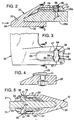
- the numeral 20 designates generally a bucket having sidewalls or wings as at 21 equipped with a forwardly-facing protector 22, and a rear wall 23 merging into a bottom wall 24.
- the bottom wall 24 terminates in a forwardly positioned lip 25.
- the lip 25 is equipped with transversely spaced-apart excavating teeth generally designated 26 (see the lower right), each of which consists of an adapter 27 fixed to the lip 25 and a point or tip 28 releasably mounted on each adapter 27.
- the lip 25 is protected by the invention through the use of upstanding bosses 29 (see the lower left) on which are mounted wear members generally designated 30.
- the wear member 30 is generally U-shaped having a longer upper or inner leg 31 in confronting relation with the upper or inner face 25a of the lip 25 and a lower or outer shorter leg 32 in confronting relation with the lower or outer face 25b of the lip 25.
- the legs 31, 32 are connected by a forwardly projecting connecting portion 33 which is generally aligned with the lip 25 and provides a cutting or penetrating edge as at 34 (see also FIG. 1).
- the boss 29 (again referring to FIG. 1) is generally T-shaped and advantageously may be welded to the lip 25. Alternatively, it may be integrally cast or bolted to the upper face 25a (compare FIGS. 6 and 4, respectively).
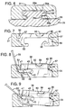
- the wear member 30 is equipped with a spaced-apart pair of rearwardly-extending legs as at 31 in FIG. 1. Only one leg is shown in FIG. 3 but each leg 31 contains a T-shaped slot 35 (see FIG. 6) which slidably receive the bosses 29.
- the bottom or inner surface 36 of the longer upper leg 31 (see FIG. 6) is equipped with the slot 35 to develop an advantageous longitudinal rearward mounting movement of the wear member 30 on the boss 29.
- the longer upper leg 31 is equipped with an opening 37 at the rear end thereof (see FIG. 3) to ensleevingly receive the boss 29.
- a lock generally designated 38 is provided.
- the lock 38 is mounted in a transversely enlarged opening 39 (compare FIGS. 2 and 3 with FIG. 7) in the outer or top surface 40 of the leg 31.
- the opening 39 communicates with the generally T-shaped slot 35 and is positioned a spaced distance rearwardly of the cutting edge 34 and forwardly of the opening 37 so as to be aligned with the rear end 41 of the T-shaped boss 29 (see FIG. 2).
- FIG. 10 where a pair of unitary steel castings or blocks 42 are seen in perspective at the upper right. Each is intended to fit within the opening 39 in the fashion illustrated in FIG. 8.
- the lock block 42 is relatively elongated transversely of each leg 31 and is equipped with a slot 43 at one end and an arcuate surface 44 at the other end.
- Received within the slot 43 is the latch assembly generally designated 45 (see FIG. 8 and 10) which includes a rubber or elastomeric body 46 bonded to a steel latch element 47.
- the slot 43 is centrally longitudinally recessed top and bottom as at 48 (see FIG. 10) to receive upstanding and depending ribs 49 on the latch assembly 45.
- the slot 43 has an inner end of partially arcuate nature as at 50 (see FIG. 10) so as to receive a similarly contoured portion 51 on the latch assembly 45.
- the lock and latch arrangement can be manufactured as one unit using a substantially non-compressible but flexible material such as rubber to be confined in the opening 39.
- FIGS. 8 and 9 The basic steps of lock removal are illustrated in FIGS. 8 and 9.
- the latch element 47 is positioned under a keeper means or tab 52 provided in the confronting sidewall 53 of the opening 39 (see FIG. 7).
- the sidewall 53 in addition to providing the keeper means 52 is slotted as at 54 (see FIGS. 3 and 10) to permit the insertion of a screwdriver tip illustrated at 55 in FIG. 8.
- the other sidewall 56 of the opening 39 is equipped with an arcuate protrusion as at 57 which is normally confronted by the arcuate recess 44 of the lock block 42 so as to provide a pivot for the block 42.
- the rubber body 46 Upon pivoting upward movement of the screwdriver tip to the position 55′ illustrated in FIG. 9, the rubber body 46 is resiliently deformed so as to retract or upset (in effect) the latch assembly 45 and this action enables the latch element 47 to pass by the keeper means 52.
- the lock 38 including the block 42 and latch assembly 45 is not adversely stressed by impact loads or forces as in the prior art.
- the lock 38 remains confined between the rear wall 41 of the boss 29 and the rear wall 58 of the opening 39 (compare FIGS. 3 and 10). This places the steel block 42 in compression but does not affect the latch assembly 45. Any stress on the latch assembly 45 merely shifts the latch element 47 under the keeper means 52.
- the block 42 is equipped with longitudinally extending flanges as at 59 (see FIG. 10) which are received within similarly contoured recesses 60 in the top wall 40 of the wear member 30 (see also FIG. 7). These elements 59-60 enable the proper positioning of the lock 38 within the opening 39.
- the invention also finds advantageous application to the sides or wings 21 as well as other earth-engaging edges of an excavator. As previously pointed out relative to FIG. 1, the wing 21 is covered by the protector 22. A sectional view is seen in FIG. 5.
- one of the excavator sides or wings is designated 21 and is seen to be equipped with the inventive wear member designated 22.
- the wear member 22 is again seen to be generally U-shaped but in this embodiment has legs 31, 31′ which are substantially of the same length in proceeding rearwardly from the forward connecting portion 33 -- as contrasted to what might be considered a J shape in the embodiment of FIG. 2.
- each leg 31, 31′ is equipped with a lock generally designated 38. More particularly, each face of the wing 21 is equipped with a T-shaped boss 29 projecting laterally therefrom.
- the legs 31, 31′ are equipped with T-shaped slots 35 for engagement with the similarly-shaped bosses 29.
- the legs 31, 31′ are provided with lock-receiving openings 39 with the remainder of the locks 38 being duplicative of that described with respect to the lip protector embodiment.
- the wear element 30 Under loading, the wear element 30 can be subjected to various force components and in resisting these, the invention provides advantages not found in the prior art.
- this component extends longitudinally, i.e., the surfaces 29a, 29b on the boss 29 and confronting surfaces 35a, 35b in the wear member slot 35 extend longitudinally so as not to affect the bearing therebetween.
- the invention provides for heavy loading and high compressive stresses on the lock generally designated 38 as a result of reaction forces resulting from normal operative loads at the leading edge of the wear member 30. It is because of this loading on the lock 38 that the invention provides an advantageous mounting for the lock 38 in the opening 39.
- the loading on the wear element 30 may produce a vertical component, viz., one at right angles to the vector T of FIG. 2. This could result in eccentric loading on the elements of the prior art supporting the wear elements but this is not the case with the instant invention.
- the invention has a boss 29 and a wear member 30 arranged so that when vertically loaded will, in contrast with prior art, minimize bending stresses in the joint between the boss 29 and the structure on which it is mounted, viz., the lip 25.
- the inventive construction with parallel surfaces of contact primarily experiences tensile stresses at the joint between the boss and the lip.
- the wear member 30 moves rearwardly on the lip 25.
- the inventive arrangement allows for substantial rearward movement before the boss 29 is encountered.
- the prior art wear edges had a very limited distance in which they could move rearwardly before contact with the upstanding boss or other retaining member. Engagement or contact between the wear member 30 and boss 29 in the prior art constructions could cause shear failure of the boss and/or unloading of the lock and subsequent loss of the lock. Further, in the prior art, a certain amount of preload was required to prevent lock disengagement which is a drawback avoided by the instant invention.
- the bearing area between the wear member and boss that supports vertical loading between the parts is advantageously large so as to avoid deformation and/or abnormal wear.
- This feature, along with the advantageous positioning of the keeper for the laterally extending latch assembly 45 achieves both the result of avoiding disengagement by undue forward movement of the wear member 30 and deterioration of the lock 38.
- the invention provides positive but releasable retention of a protective wear member to the leading edge of a bucket lip or bucket wings or sidewalls -- these latter also having wearable edges like the bucket lip.
- Exemplary of the invention is a wear member utilized to protect the leading edge of a large front end loader bucket lip. Protection of earth-engaging bucket lips is a constant maintenance problem and many forms of protection have been utilized over the years. Normally, wear edge protectors are welded, bolted, or mechanically attached. The most desirable designs are those that are mechanically attached and easy to install and remove. Although the structure is illustrated for a front end loader lip and wings, variations of this design could be utilized on face shovels, cable shovels, draglines and other earth moving equipment.
- the invention includes an easily changeable wear member 30 with one or more rearwardly projecting portions or legs 31.
- the leg 31 includes a T-shaped longitudinally extending slot 35 which engages a mating or similarly contoured boss 29.
- the required number of bosses may either be bolted or welded to the lip or integrally cast therewith.
- the wear member 30 is releasably held in position by means of a lock 38 installed in a generally rectangular opening 39 (see FIG. 3) in each leg 31.
- the transversely enlarged opening 39 is located rearwardly of the rear end of the boss 29.
- the lock opening 39 has an arcuate protrusion 57 (see FIG. 7) at the upper edge normal to the leading edge or forward wall of the opening 39.
- the arcuate protrusion 57 serves as a pivot point for installation of the lock as illustrated in FIG. 9.
- the sidewall 53 opposite to that equipped with the arcuate protrusion 57 is equipped with a tab or keeper means 52 which retains the latch assembly 45 in place -- until the rubber body 46 is deformed under the influence of a screw driver tip 55 so as to permit passage of the latch element 47 past the keeper means 52.
- the latch assembly 45 is not substantially subjected to adverse stresses yet is advantageously located for easy replacement.
Landscapes
- Engineering & Computer Science (AREA)
- Mining & Mineral Resources (AREA)
- Civil Engineering (AREA)
- General Engineering & Computer Science (AREA)
- Structural Engineering (AREA)
- Component Parts Of Construction Machinery (AREA)
- Earth Drilling (AREA)
- Mechanical Operated Clutches (AREA)
- Mechanical Pencils And Projecting And Retracting Systems Therefor, And Multi-System Writing Instruments (AREA)
- Bidet-Like Cleaning Device And Other Flush Toilet Accessories (AREA)
- Coating By Spraying Or Casting (AREA)
- Blast Furnaces (AREA)
- Paper (AREA)
- Adornments (AREA)
- Electrochromic Elements, Electrophoresis, Or Variable Reflection Or Absorption Elements (AREA)
- Steroid Compounds (AREA)
Applications Claiming Priority (3)
| Application Number | Priority Date | Filing Date | Title |
|---|---|---|---|
| US642390 | 1991-01-17 | ||
| US07/642,390 US5088214A (en) | 1991-01-17 | 1991-01-17 | Excavator wear edge |
| PCT/US1992/000197 WO1992013145A1 (en) | 1991-01-17 | 1992-01-13 | Excavating wear edge with resilient lock |
Publications (3)
| Publication Number | Publication Date |
|---|---|
| EP0530330A1 EP0530330A1 (en) | 1993-03-10 |
| EP0530330A4 EP0530330A4 (en) | 1993-06-09 |
| EP0530330B1 true EP0530330B1 (en) | 1995-10-11 |
Family
ID=24576348
Family Applications (1)
| Application Number | Title | Priority Date | Filing Date |
|---|---|---|---|
| EP92903826A Expired - Lifetime EP0530330B1 (en) | 1991-01-17 | 1992-01-13 | Excavating wear edge with resilient lock |
Country Status (24)
Cited By (1)
| Publication number | Priority date | Publication date | Assignee | Title |
|---|---|---|---|---|
| CN101253298B (zh) * | 2005-08-30 | 2012-07-18 | 爱斯科公司 | 用于挖掘机的耐磨损总成 |
Families Citing this family (135)
| Publication number | Priority date | Publication date | Assignee | Title |
|---|---|---|---|---|
| US6735890B2 (en) * | 2001-07-06 | 2004-05-18 | Esco Corporation | Wear assembly |
| US5172501A (en) * | 1990-06-21 | 1992-12-22 | Pippins Sherlock K | Tooth assembly for excavating apparatus |
| US5241765A (en) * | 1991-01-17 | 1993-09-07 | Esco Corporation | Lock assembly for wearable structure |
| US5224555A (en) * | 1991-12-18 | 1993-07-06 | Bucyrus Blades, Inc. | Wear element for a scraping operation |
| US5333696A (en) * | 1992-11-02 | 1994-08-02 | Caterpillar Inc. | Reversible protector for a work member |
| AU659951B2 (en) * | 1992-11-18 | 1995-06-01 | Dural International Pty. Ltd. | Wear resistant blocks and associated retaining insert plates |
| FR2708973B1 (fr) * | 1993-03-29 | 1995-10-27 | Pasqualini Charles | Dispositif et procédé de liaison entre des dents amovibles et des adapteurs formés aux extrémités d'outils et réceptacles en usage sur les engins de travaux publics. |
| US5337495A (en) * | 1993-04-30 | 1994-08-16 | Pippins Sherlock K | Tooth assembly for excavating apparatus |
| US5412885A (en) * | 1993-07-02 | 1995-05-09 | Caterpillar Inc. | Bucket base edge protector assembly |
| US5526592A (en) * | 1994-07-22 | 1996-06-18 | Bierwith; Robert S. | Tooth assembly for excavation bucket |
| US5564508A (en) * | 1995-08-03 | 1996-10-15 | Caterpillar Inc. | Replacable wear runner |
| US5553409A (en) * | 1995-08-22 | 1996-09-10 | Foothills Steel Foundry Ltd. | Shroud anchor system |
| US5634285A (en) * | 1995-09-29 | 1997-06-03 | Caterpillar Inc. | Base edge cover for a bucket and apparatus for retaining same |
| US5653048A (en) | 1995-11-06 | 1997-08-05 | Esco Corporation | Wear assembly for a digging edge of an excavator |
| US5666748A (en) * | 1995-12-11 | 1997-09-16 | Esco Corporation | Wear cap and components useable therewith |
| US5937550A (en) * | 1995-12-11 | 1999-08-17 | Esco Corporation | Extensible lock |
| US5709043A (en) * | 1995-12-11 | 1998-01-20 | Esco Corporation | Excavating tooth |
| US5937549A (en) * | 1996-08-08 | 1999-08-17 | Caterpillar Inc. | Wear member attachment system |
| US5913605A (en) * | 1997-09-17 | 1999-06-22 | G. H. Hensley Industries, Inc. | Rotary lock system for wear runner assembly |
| US6085448A (en) * | 1997-10-30 | 2000-07-11 | Caterpillar Inc. | Mechanical retention system for ground engaging tools |
| CA2305617A1 (en) * | 1997-10-30 | 1999-05-14 | Richard E. Livesay | Mechanical retention system for ground engaging tools |
| US6041529A (en) * | 1998-03-18 | 2000-03-28 | G. H. Hensley Industries, Inc. | Bolt-on wear runner assembly for material handling/displacement apparatus |
| ES2146541B1 (es) * | 1998-06-08 | 2001-04-01 | Metalogenia Sa | Dispositivo para el acoplamiento de dientes de excavadoras. |
| ES2146174B1 (es) | 1998-07-03 | 2002-01-16 | Metalogenia Sa | Acoplamiento para dientes de excavadoras y similares. |
| US6145224A (en) * | 1998-11-06 | 2000-11-14 | Caterpillar Inc. | Ground engaging tools for earthworking implements and retainer therefor |
| US6194080B1 (en) * | 1998-12-16 | 2001-02-27 | Caterpillar Inc. | Replaceable wear member |
| US6467203B2 (en) | 1999-04-05 | 2002-10-22 | Trn Business Trust | Removable tooth assembly retention system and method |
| US6374521B1 (en) | 1999-04-05 | 2002-04-23 | Trn Business Trust | Apparatus and method for coupling an excavation tooth assembly |
| US6725582B2 (en) * | 1999-06-10 | 2004-04-27 | Quality Steel Foundries Ltd. | Assembly for fastening a ground engaging tool to a support structure |
| ES2158805B1 (es) * | 1999-10-01 | 2002-04-01 | Metalogenia Sa | Perfeccionamientos en los acoplamientos para dientes de maquinas para movimiento de tierras. |
| US6751897B2 (en) | 2000-11-27 | 2004-06-22 | Robert S. Bierwith | Lip assembly |
| WO2002073697A1 (en) * | 2001-03-12 | 2002-09-19 | Hitachi, Ltd. | Semiconductor integrated circuit device and process for producing the same |
| AUPR576701A0 (en) * | 2001-06-18 | 2001-07-12 | Keech Castings Australia Pty Limited | Locking assembly and method |
| WO2003004782A2 (en) * | 2001-07-06 | 2003-01-16 | Esco Corporation | Coupling for excavating wear part |
| US6467204B1 (en) | 2001-08-09 | 2002-10-22 | Trn Business Trust | Adapter assembly having multiple retainer pins |
| US6574892B2 (en) | 2001-09-05 | 2003-06-10 | Trn Business Trust | Retainer pin having an internal secondary retainer pin |
| US7266914B2 (en) | 2001-10-09 | 2007-09-11 | Peninsula Alloy Inc. | Wear plate assembly |
| US6729052B2 (en) * | 2001-11-09 | 2004-05-04 | Esco Corporation | Assembly for securing an excavating tooth |
| US6799387B2 (en) | 2002-01-29 | 2004-10-05 | Trn Business Trust | Removable adapter assembly having a retractable insert |
| US6757995B2 (en) | 2002-07-12 | 2004-07-06 | Trn Business Trust | System and method for coupling excavation equipment components |
| JP2004124414A (ja) * | 2002-09-30 | 2004-04-22 | Echigo Shoji Kk | ショベル機械用のバケットに付設されるツース盤及びショベル機械用のバケット |
| US20040118021A1 (en) * | 2002-12-23 | 2004-06-24 | Renski Williams J. | Longitudinal orientation of a retainer for a bucket tip |
| US7080470B2 (en) * | 2003-04-30 | 2006-07-25 | Esco Corporation | Wear assembly for excavator digging edge |
| US6986216B2 (en) * | 2003-04-30 | 2006-01-17 | Esco Corporation | Wear assembly for the digging edge of an excavator |
| US7036249B2 (en) | 2003-05-22 | 2006-05-02 | Trn Business Trust | Tooth adapter having an elastomeric clamp assembly and method for using same |
| US20050132619A1 (en) * | 2003-12-23 | 2005-06-23 | Robinson Howard W. | Excavating lip-mounted adapter and associated connection and shielding apparatus |
| US7596895B2 (en) * | 2004-03-30 | 2009-10-06 | Esco Corporation | Wear assembly |
| US20050229442A1 (en) * | 2004-03-30 | 2005-10-20 | Esco Corporation | Wear edge assembly |
| US7032334B2 (en) * | 2004-05-28 | 2006-04-25 | Trn Business Trust | System and method for coupling excavation equipment components |
| AU2006201511A1 (en) * | 2005-04-12 | 2006-10-26 | Esco Corporation | Wear assembly |
| MY149408A (en) * | 2005-08-30 | 2013-08-30 | Esco Corp | Wear assembly for excavating machines |
| TWI387675B (zh) * | 2005-12-21 | 2013-03-01 | Esco Corp | 磨耗元件、磨耗總成及用於鎖的短管 |
| NZ594016A (en) | 2006-03-30 | 2012-11-30 | Esco Corp | Wear teeth for bucket edge teeth of digging machines |
| PE20080597A1 (es) * | 2006-04-24 | 2008-05-17 | Esco Corp | Montaje de desgaste |
| CA2652603C (en) * | 2006-06-16 | 2013-01-15 | Esco Corporation | Lock for securing wear parts to earth-working equipment |
| US20080005940A1 (en) * | 2006-07-10 | 2008-01-10 | Esco Corporation | Assembly for securing a wear |
| PL2076633T3 (pl) | 2006-10-24 | 2017-06-30 | Esco Corporation | Zespół ochronny dla łyżki koparkowej |
| US20080092412A1 (en) * | 2006-10-24 | 2008-04-24 | Esco Corporation | Wear Assembly For An Excavating Bucket |
| DE102006055753B4 (de) * | 2006-11-25 | 2008-10-23 | Terex Gmbh | Aufnahmeelement für Schüttgut |
| AU2006252273B2 (en) * | 2006-12-22 | 2013-10-03 | Sandvik Mining & Construction Australia (Production/Supply) Pty Ltd | Attachment system |
| US20080201995A1 (en) * | 2007-02-27 | 2008-08-28 | Dan Browder | Excavator attachment apparatus for loader bucket |
| CA2719712C (en) | 2007-03-29 | 2013-11-19 | Cqms Pty Ltd | Mounting of wear members |
| US8468725B2 (en) | 2007-04-03 | 2013-06-25 | Cqms Pty Ltd | Mounting pin assembly for an excavator wear member |
| US7874086B2 (en) * | 2007-04-24 | 2011-01-25 | Esco Corporation | Lock assembly for securing a wear member to earth-working equipment |
| CA2639138C (en) * | 2007-08-23 | 2017-10-10 | Wearforce Pty Ltd. | Shroud assembly |
| CN101868326B (zh) | 2007-11-26 | 2015-02-18 | 爱斯科公司 | 销轴连接器 |
| WO2009127016A1 (en) * | 2008-04-18 | 2009-10-22 | Cqms Pty Ltd | A lock assembly for an excavator wear member |
| US8261472B2 (en) | 2009-03-23 | 2012-09-11 | Black Cat Blades Ltd. | Retrofitted excavator tooth attachment |
| AU325605S (en) * | 2009-04-03 | 2009-04-06 | Blupoint Pty Ltd | Ground engaging tool |
| DE102009029894B4 (de) * | 2009-06-23 | 2019-03-21 | Betek Gmbh & Co. Kg | Bodenbearbeitungswerkzeug |
| BR112012014006B8 (pt) | 2009-12-11 | 2022-07-26 | Cqms Pty Ltd | Conjunto de trava para um membro de desgaste de escavadeira e conjunto de desgaste de escavadeira |
| US8302333B2 (en) | 2010-04-27 | 2012-11-06 | Black Cat Blades Ltd. | Excavation tooth lip adapter and fastening system therefor |
| CN101967837A (zh) * | 2010-09-13 | 2011-02-09 | 江苏宜鹏锻压机械制造有限公司 | 一种挖掘机的铲斗斗唇及其制备方法 |
| AU2012203050B2 (en) * | 2011-05-26 | 2016-12-15 | Bradken Resources Pty Limited | Wear Assembly |
| BR112014004312B8 (pt) | 2011-08-26 | 2022-05-03 | Black Cat Blades Ltd | Unidade de desgaste protetora para aparelho de manuseio de material |
| US10011977B2 (en) | 2011-09-08 | 2018-07-03 | Miguel Guimaraes | Lock assembly for an excavator wear member |
| US8720962B2 (en) * | 2011-11-10 | 2014-05-13 | Louis Ceja | Shovel |
| US9476184B2 (en) | 2011-12-08 | 2016-10-25 | Cqms Pty Ltd | Excavator wear assembly |
| US8959807B2 (en) * | 2011-12-13 | 2015-02-24 | Caterpillar Inc. | Edge protector for ground engaging tool assembly |
| US8336233B1 (en) | 2012-04-06 | 2012-12-25 | Gaetano Lombardo | Wear plate assembly |
| ES2644068T3 (es) * | 2012-09-21 | 2017-11-27 | Liebherr-Mining Equipment Colmar Sas | Cubierta de ala para una cuchara de una máquina de movimiento de tierra; y máquina de movimiento de tierra |
| JP6166121B2 (ja) * | 2013-08-01 | 2017-07-19 | 越後商事株式会社 | バケット先端の隠蔽用アダプタ及び掘削等を行う作業機械に取り付けられるバケット |
| CN103410187B (zh) * | 2013-08-06 | 2016-03-16 | 中国神华能源股份有限公司 | 一种斗栓装置 |
| US9969283B2 (en) | 2013-09-10 | 2018-05-15 | General Electric Company | Battery changing system and method |
| US9359745B2 (en) * | 2013-10-15 | 2016-06-07 | Caterpillar Inc. | Bucket edge protection system |
| RU2666820C2 (ru) * | 2013-10-17 | 2018-09-12 | Харнишфигер Текнолоджиз, Инк. | Система обшивки для ковша |
| US9404240B2 (en) | 2013-11-07 | 2016-08-02 | Caterpillar Inc. | Bucket lip protection assemblies and lip adapters for same |
| US9518379B2 (en) | 2014-02-28 | 2016-12-13 | Caterpillar Inc. | Shroud retention system having replaceable lug insert |
| EP2913446A1 (en) * | 2014-02-28 | 2015-09-02 | Caterpillar Work Tools B. V. | Lip shroud for a dragline lip |
| EP2913445A1 (en) | 2014-02-28 | 2015-09-02 | Caterpillar Work Tools B. V. | Wing shroud for a dragline lip |
| WO2015135027A1 (en) * | 2014-03-13 | 2015-09-17 | Bradken Uk Limited | Wear assembly |
| US20140325881A1 (en) * | 2014-07-16 | 2014-11-06 | Caterpillar Inc. | Wear assembly |
| CN104196076A (zh) * | 2014-09-05 | 2014-12-10 | 河海大学常州校区 | 绞吸式挖泥船用绞刀 |
| US9903101B2 (en) * | 2014-12-05 | 2018-02-27 | Caterpillar Inc. | Replaceable shroud for work implement |
| USD769945S1 (en) | 2014-12-05 | 2016-10-25 | Caterpillar Inc. | Sidebar protector |
| CA3001369C (en) * | 2015-02-13 | 2019-07-02 | Black Cat Blades Ltd. | Wear members for excavation implements |
| WO2016149275A1 (en) * | 2015-03-16 | 2016-09-22 | Dervin Andrew | Receptacle filling ramp |
| USD767647S1 (en) | 2015-04-17 | 2016-09-27 | Caterpillar Inc. | Lip shroud for ground engaging machine implement |
| USD769946S1 (en) | 2015-04-17 | 2016-10-25 | Caterpillar Inc. | Lip for ground engaging machine implement |
| USD766994S1 (en) | 2015-04-17 | 2016-09-20 | Caterpillar Inc. | Wing shroud for ground engaging machine implement |
| CN106661874B (zh) | 2015-06-05 | 2018-11-27 | 布莱凯特有限公司 | 挖掘工具的耐磨构件附接系统 |
| US9670648B2 (en) | 2015-08-10 | 2017-06-06 | Caterpillar Inc. | Replaceable tip systems for a tine |
| US10273663B2 (en) * | 2015-08-24 | 2019-04-30 | Caterpillar Inc. | Shroud collar for edge protection of a work tool |
| JP6732895B2 (ja) * | 2015-09-29 | 2020-07-29 | エスコ・グループ・エルエルシー | 土壌作業装置のための摩耗アセンブリ |
| USD788826S1 (en) | 2016-02-09 | 2017-06-06 | Caterpillar Inc. | Sidebar protector |
| USD802865S1 (en) | 2016-03-04 | 2017-11-14 | Valencia Pipe Company, Inc. | Trash receptacle loading ramp |
| EP3452664B1 (en) | 2016-05-05 | 2021-12-08 | ESCO Group LLC | A wear part for earth working equipment |
| US10519632B2 (en) * | 2016-05-13 | 2019-12-31 | Caterpillar Inc. | Shroud insert assembly using a resilient member |
| CN107574856A (zh) * | 2016-07-05 | 2018-01-12 | 天津卡斯特机械有限公司 | 一种挖掘机用可更换斗齿的铲斗 |
| USD797162S1 (en) | 2016-07-21 | 2017-09-12 | Caterpillar Inc. | Lip for ground engaging machine implement and/or digital representation thereof |
| USD797163S1 (en) | 2016-07-21 | 2017-09-12 | Caterpillar Inc. | Lip shroud for ground engaging machine implement and/or digital representation thereof |
| EP3502361B1 (en) * | 2016-08-18 | 2020-07-22 | Metalogenia Research & Technologies S.L. | Fastening device for a wearing or protection element in the bucket of an earth moving machine and corresponding fastening system and procedure |
| USD842345S1 (en) | 2017-07-21 | 2019-03-05 | Caterpillar Inc. | Lip shroud for a ground engaging machine implement |
| USD832309S1 (en) | 2017-08-30 | 2018-10-30 | Caterpillar Inc. | Lip shroud for a ground engaging machine implement |
| USD842346S1 (en) | 2017-10-11 | 2019-03-05 | Caterpillar Inc. | Shroud for a ground engaging machine implement |
| USD842347S1 (en) | 2017-10-11 | 2019-03-05 | Caterpillar Inc. | Shroud for a ground engaging machine implement |
| JOP20200249A1 (ar) | 2018-03-30 | 2019-09-30 | Esco Group Llc | عضو تآكل، وحافة وعملية تركيب |
| USD882645S1 (en) | 2018-10-03 | 2020-04-28 | Caterpillar Inc. | Bucket shroud |
| USD873306S1 (en) | 2018-10-03 | 2020-01-21 | Caterpillar Inc. | Bucket shroud |
| USD882644S1 (en) | 2018-10-03 | 2020-04-28 | Caterpillar Inc. | Bucket shroud |
| USD882646S1 (en) | 2018-11-09 | 2020-04-28 | Caterpillar Inc. | Bucket shroud |
| US10428494B1 (en) | 2018-12-07 | 2019-10-01 | Pasquale Lombardo | Wear plate assembly with two-part key assembly |
| CA3122287A1 (en) * | 2018-12-20 | 2020-06-25 | Esco Group Llc | Wear member and wear assembly |
| USD905764S1 (en) * | 2019-03-07 | 2020-12-22 | Caterpillar Inc. | Adapter cover for a ground engaging machine implement |
| USD905763S1 (en) | 2019-03-07 | 2020-12-22 | Caterpillar Inc. | Adapter cover for a ground engaging machine implement |
| US20220243430A1 (en) * | 2019-07-22 | 2022-08-04 | 2Mt Mining Products Pty Ltd. | Retainer systems |
| USD927561S1 (en) | 2019-10-04 | 2021-08-10 | Caterpillar Inc. | Bucket shroud |
| USD928849S1 (en) | 2019-10-04 | 2021-08-24 | Caterpillar Inc. | Bucket shroud |
| USD928848S1 (en) | 2019-10-04 | 2021-08-24 | Caterpillar Inc. | Bucket shroud |
| WO2021155472A1 (en) * | 2020-02-05 | 2021-08-12 | 9257-5810 Québec Inc. | Wear member assembly for earth working bucket |
| US11220806B2 (en) | 2020-03-09 | 2022-01-11 | Pasquale Lombardo | Corner wear plate assembly |
| USD983234S1 (en) | 2020-11-18 | 2023-04-11 | Caterpillar Inc. | Adapter cover for a ground engaging machine implement |
| USD945500S1 (en) | 2020-11-18 | 2022-03-08 | Caterpillar Inc. | Adapter cover for a ground engaging machine implement |
| USD959505S1 (en) | 2021-03-25 | 2022-08-02 | Caterpillar Inc. | Bucket shroud |
| USD978923S1 (en) | 2021-06-03 | 2023-02-21 | Caterpillar Inc. | Bucket shroud |
Family Cites Families (22)
| Publication number | Priority date | Publication date | Assignee | Title |
|---|---|---|---|---|
| US1544222A (en) * | 1921-10-22 | 1925-06-30 | American Hoist & Derrick Co | Dipper-tooth point for excavating shovels |
| US2870667A (en) * | 1954-07-08 | 1959-01-27 | American Brake Shoe Co | Retaining key for dipper tooth parts having resilient pad |
| GB846248A (en) * | 1959-02-25 | 1960-08-31 | Electric Steel Foundry Co | Improvements in tooth assemblies for digging apparatus |
| US3171500A (en) * | 1962-04-04 | 1965-03-02 | Esco Corp | Ground working device |
| US3388488A (en) * | 1965-11-29 | 1968-06-18 | Duplessis Gerard | Bucket and adaptor assembly for digging teeth |
| US3497973A (en) * | 1967-05-01 | 1970-03-03 | Caterpillar Tractor Co | Compact high strength replaceable cutting edge |
| US3621594A (en) * | 1969-02-13 | 1971-11-23 | Esco Corp | Cutting edge for excavating devices |
| US3708895A (en) * | 1970-04-29 | 1973-01-09 | Florida Machine & Foundry Co | Replaceable tooth assembly |
| US3685177A (en) * | 1970-08-13 | 1972-08-22 | Esco Corp | Two piece cutting edge |
| US3762079A (en) * | 1972-10-02 | 1973-10-02 | Caterpillar Tractor Co | Quick-change cutting edge |
| US3864853A (en) * | 1973-04-27 | 1975-02-11 | Caterpillar Tractor Co | Quick disconnect cutting edge for earthworking implements |
| US3995384A (en) * | 1974-11-25 | 1976-12-07 | John F. Duncan | Edge bit structure for implement blade |
| CA1059556A (en) * | 1976-05-04 | 1979-07-31 | Esco Corporation | Locking device for earth moving tool |
| US4449309A (en) * | 1979-03-05 | 1984-05-22 | Gh Hensley Industries, Inc. | Flat bottom bucket and digging teeth |
| US4290214A (en) * | 1980-02-04 | 1981-09-22 | Caterpillar Tractor Co. | Earthworking implement side plate wear member |
| US4335532A (en) * | 1980-04-28 | 1982-06-22 | Esco Corporation | Excavating tooth |
| US4404760A (en) * | 1980-04-28 | 1983-09-20 | Esco Corporation | Excavating tooth |
| SE445125B (sv) * | 1981-03-26 | 1986-06-02 | Bofors Ab | Slitdelssystem for jordbearbetningsmaskiner |
| US4501079A (en) * | 1983-08-24 | 1985-02-26 | Esco Corporation | Two piece cutting edge construction |
| DE3611493A1 (de) * | 1986-04-05 | 1987-10-15 | Orenstein & Koppel Ag | Grabschaufel fuer bagger |
| US4932478A (en) * | 1988-08-22 | 1990-06-12 | Esco Corporation | Tooth point for earth working |
| US5016365A (en) * | 1989-06-06 | 1991-05-21 | Gh Hensley Industries, Inc. | Wear parts for excavation apparatus |
-
1991
- 1991-01-17 US US07/642,390 patent/US5088214A/en not_active Expired - Lifetime
-
1992
- 1992-01-03 ZA ZA9233A patent/ZA9233B/xx unknown
- 1992-01-06 MY MYPI96002389A patent/MY119043A/en unknown
- 1992-01-06 MY MYPI92000024A patent/MY108171A/en unknown
- 1992-01-13 AT AT92903826T patent/ATE129039T1/de not_active IP Right Cessation
- 1992-01-13 DK DK92903826.3T patent/DK0530330T3/da active
- 1992-01-13 KR KR1019920702242A patent/KR970001731B1/ko not_active Expired - Fee Related
- 1992-01-13 HK HK98104775A patent/HK1005598A1/en not_active IP Right Cessation
- 1992-01-13 CA CA002076019A patent/CA2076019C/en not_active Expired - Lifetime
- 1992-01-13 DE DE69205378T patent/DE69205378T2/de not_active Expired - Lifetime
- 1992-01-13 WO PCT/US1992/000197 patent/WO1992013145A1/en active IP Right Grant
- 1992-01-13 AU AU11889/92A patent/AU642377B2/en not_active Expired
- 1992-01-13 ES ES92903826T patent/ES2079179T3/es not_active Expired - Lifetime
- 1992-01-13 BR BR9205368A patent/BR9205368A/pt not_active IP Right Cessation
- 1992-01-13 TW TW081100186A patent/TW200551B/zh active
- 1992-01-13 EP EP92903826A patent/EP0530330B1/en not_active Expired - Lifetime
- 1992-01-13 JP JP4503838A patent/JPH0819698B2/ja not_active Expired - Lifetime
- 1992-01-15 TR TR92/0031A patent/TR25592A/xx unknown
- 1992-01-15 NZ NZ241315A patent/NZ241315A/xx not_active IP Right Cessation
- 1992-01-17 PT PT100039A patent/PT100039B/pt not_active IP Right Cessation
- 1992-01-17 CN CN92200880U patent/CN2108126U/zh active Granted
- 1992-01-17 MX MX9200227A patent/MX9200227A/es unknown
- 1992-09-16 NO NO923604A patent/NO180727C/no unknown
- 1992-09-16 FI FI924152A patent/FI104842B/fi active
-
1995
- 1995-10-12 GR GR950402385T patent/GR3017725T3/el unknown
-
1997
- 1997-03-07 JP JP9053671A patent/JP2807452B2/ja not_active Expired - Lifetime
Cited By (1)
| Publication number | Priority date | Publication date | Assignee | Title |
|---|---|---|---|---|
| CN101253298B (zh) * | 2005-08-30 | 2012-07-18 | 爱斯科公司 | 用于挖掘机的耐磨损总成 |
Also Published As
Similar Documents
| Publication | Publication Date | Title |
|---|---|---|
| EP0530330B1 (en) | Excavating wear edge with resilient lock | |
| HK1005598B (en) | Excavating wear edge with resilient lock | |
| US5241765A (en) | Lock assembly for wearable structure | |
| KR101297529B1 (ko) | 굴착기용 마모 조립체 | |
| US6952892B1 (en) | Lip assembly | |
| USRE43693E1 (en) | Coupling arrangement | |
| US5653048A (en) | Wear assembly for a digging edge of an excavator | |
| US20060225313A1 (en) | Wear assembly | |
| KR20060134135A (ko) | 마모 모서리 조립체 | |
| US7874086B2 (en) | Lock assembly for securing a wear member to earth-working equipment | |
| US6216368B1 (en) | Excavating bucket with replaceable wedge-locked teeth | |
| EA007026B1 (ru) | Изнашиваемое устройство для режущей кромки землеройного ковша | |
| US3839806A (en) | Two-piece router bit assembly | |
| HK1102136A (en) | Wear edge assembly |
Legal Events
| Date | Code | Title | Description |
|---|---|---|---|
| PUAI | Public reference made under article 153(3) epc to a published international application that has entered the european phase |
Free format text: ORIGINAL CODE: 0009012 |
|
| AK | Designated contracting states |
Kind code of ref document: A1 Designated state(s): AT BE CH DE DK ES FR GB GR IT LI LU NL SE |
|
| 17P | Request for examination filed |
Effective date: 19930204 |
|
| A4 | Supplementary search report drawn up and despatched |
Effective date: 19930421 |
|
| AK | Designated contracting states |
Kind code of ref document: A4 Designated state(s): AT BE CH DE DK ES FR GB GR IT LI LU NL SE |
|
| 17Q | First examination report despatched |
Effective date: 19941124 |
|
| GRAA | (expected) grant |
Free format text: ORIGINAL CODE: 0009210 |
|
| AK | Designated contracting states |
Kind code of ref document: B1 Designated state(s): AT BE CH DE DK ES FR GB GR IT LI LU NL SE |
|
| REF | Corresponds to: |
Ref document number: 129039 Country of ref document: AT Date of ref document: 19951015 Kind code of ref document: T |
|
| REF | Corresponds to: |
Ref document number: 69205378 Country of ref document: DE Date of ref document: 19951116 |
|
| ET | Fr: translation filed | ||
| REG | Reference to a national code |
Ref country code: GR Ref legal event code: FG4A Free format text: 3017725 |
|
| PGFP | Annual fee paid to national office [announced via postgrant information from national office to epo] |
Ref country code: NL Payment date: 19951231 Year of fee payment: 5 |
|
| REG | Reference to a national code |
Ref country code: ES Ref legal event code: FG2A Ref document number: 2079179 Country of ref document: ES Kind code of ref document: T3 |
|
| ITF | It: translation for a ep patent filed | ||
| PGFP | Annual fee paid to national office [announced via postgrant information from national office to epo] |
Ref country code: LU Payment date: 19960201 Year of fee payment: 5 |
|
| REG | Reference to a national code |
Ref country code: DK Ref legal event code: T3 |
|
| PLBE | No opposition filed within time limit |
Free format text: ORIGINAL CODE: 0009261 |
|
| STAA | Information on the status of an ep patent application or granted ep patent |
Free format text: STATUS: NO OPPOSITION FILED WITHIN TIME LIMIT |
|
| 26N | No opposition filed | ||
| PGFP | Annual fee paid to national office [announced via postgrant information from national office to epo] |
Ref country code: DK Payment date: 19961218 Year of fee payment: 6 |
|
| PGFP | Annual fee paid to national office [announced via postgrant information from national office to epo] |
Ref country code: GR Payment date: 19961223 Year of fee payment: 6 Ref country code: AT Payment date: 19961223 Year of fee payment: 6 |
|
| PG25 | Lapsed in a contracting state [announced via postgrant information from national office to epo] |
Ref country code: LU Free format text: LAPSE BECAUSE OF NON-PAYMENT OF DUE FEES Effective date: 19970113 |
|
| PGFP | Annual fee paid to national office [announced via postgrant information from national office to epo] |
Ref country code: BE Payment date: 19970206 Year of fee payment: 6 |
|
| PGFP | Annual fee paid to national office [announced via postgrant information from national office to epo] |
Ref country code: CH Payment date: 19970422 Year of fee payment: 6 |
|
| PG25 | Lapsed in a contracting state [announced via postgrant information from national office to epo] |
Ref country code: NL Effective date: 19970801 |
|
| NLV4 | Nl: lapsed or anulled due to non-payment of the annual fee |
Effective date: 19970801 |
|
| PG25 | Lapsed in a contracting state [announced via postgrant information from national office to epo] |
Ref country code: AT Free format text: LAPSE BECAUSE OF NON-PAYMENT OF DUE FEES Effective date: 19980113 |
|
| PG25 | Lapsed in a contracting state [announced via postgrant information from national office to epo] |
Ref country code: LI Free format text: LAPSE BECAUSE OF NON-PAYMENT OF DUE FEES Effective date: 19980131 Ref country code: GR Free format text: LAPSE BECAUSE OF NON-PAYMENT OF DUE FEES Effective date: 19980131 Ref country code: CH Free format text: LAPSE BECAUSE OF NON-PAYMENT OF DUE FEES Effective date: 19980131 Ref country code: BE Free format text: LAPSE BECAUSE OF NON-PAYMENT OF DUE FEES Effective date: 19980131 |
|
| PG25 | Lapsed in a contracting state [announced via postgrant information from national office to epo] |
Ref country code: DK Free format text: LAPSE BECAUSE OF NON-PAYMENT OF DUE FEES Effective date: 19980202 |
|
| BERE | Be: lapsed |
Owner name: ESCO CORP. Effective date: 19980131 |
|
| REG | Reference to a national code |
Ref country code: CH Ref legal event code: PL |
|
| REG | Reference to a national code |
Ref country code: DK Ref legal event code: EBP |
|
| REG | Reference to a national code |
Ref country code: GB Ref legal event code: IF02 |
|
| PGFP | Annual fee paid to national office [announced via postgrant information from national office to epo] |
Ref country code: FR Payment date: 20110301 Year of fee payment: 20 Ref country code: IT Payment date: 20110126 Year of fee payment: 20 Ref country code: DE Payment date: 20110127 Year of fee payment: 20 Ref country code: SE Payment date: 20110127 Year of fee payment: 20 |
|
| PGFP | Annual fee paid to national office [announced via postgrant information from national office to epo] |
Ref country code: GB Payment date: 20110125 Year of fee payment: 20 Ref country code: ES Payment date: 20110126 Year of fee payment: 20 |
|
| REG | Reference to a national code |
Ref country code: DE Ref legal event code: R071 Ref document number: 69205378 Country of ref document: DE |
|
| REG | Reference to a national code |
Ref country code: DE Ref legal event code: R071 Ref document number: 69205378 Country of ref document: DE |
|
| REG | Reference to a national code |
Ref country code: GB Ref legal event code: PE20 Expiry date: 20120112 |
|
| REG | Reference to a national code |
Ref country code: SE Ref legal event code: EUG |
|
| PG25 | Lapsed in a contracting state [announced via postgrant information from national office to epo] |
Ref country code: DE Free format text: LAPSE BECAUSE OF EXPIRATION OF PROTECTION Effective date: 20120114 |
|
| REG | Reference to a national code |
Ref country code: ES Ref legal event code: FD2A Effective date: 20120510 |
|
| PG25 | Lapsed in a contracting state [announced via postgrant information from national office to epo] |
Ref country code: GB Free format text: LAPSE BECAUSE OF EXPIRATION OF PROTECTION Effective date: 20120112 |
|
| PG25 | Lapsed in a contracting state [announced via postgrant information from national office to epo] |
Ref country code: ES Free format text: LAPSE BECAUSE OF EXPIRATION OF PROTECTION Effective date: 20120114 |