EP0528321B1 - Vorrichtung zum Einsetzen und Einschweissen von flachen Formteilen in Ausnehmungen von Platinen - Google Patents
Vorrichtung zum Einsetzen und Einschweissen von flachen Formteilen in Ausnehmungen von Platinen Download PDFInfo
- Publication number
- EP0528321B1 EP0528321B1 EP92113611A EP92113611A EP0528321B1 EP 0528321 B1 EP0528321 B1 EP 0528321B1 EP 92113611 A EP92113611 A EP 92113611A EP 92113611 A EP92113611 A EP 92113611A EP 0528321 B1 EP0528321 B1 EP 0528321B1
- Authority
- EP
- European Patent Office
- Prior art keywords
- plate
- clamping table
- shaped part
- centring
- welding
- Prior art date
- Legal status (The legal status is an assumption and is not a legal conclusion. Google has not performed a legal analysis and makes no representation as to the accuracy of the status listed.)
- Expired - Lifetime
Links
- 238000003466 welding Methods 0.000 title claims description 28
- 238000003780 insertion Methods 0.000 claims description 3
- 230000037431 insertion Effects 0.000 claims description 3
- BASFCYQUMIYNBI-UHFFFAOYSA-N platinum Chemical compound [Pt] BASFCYQUMIYNBI-UHFFFAOYSA-N 0.000 description 8
- 238000000034 method Methods 0.000 description 2
- 238000000465 moulding Methods 0.000 description 2
- 230000001360 synchronised effect Effects 0.000 description 2
- 230000004913 activation Effects 0.000 description 1
- 239000003302 ferromagnetic material Substances 0.000 description 1
- 239000000463 material Substances 0.000 description 1
- 239000002184 metal Substances 0.000 description 1
- 230000000717 retained effect Effects 0.000 description 1
- 230000008646 thermal stress Effects 0.000 description 1
Images


Classifications
-
- B—PERFORMING OPERATIONS; TRANSPORTING
- B23—MACHINE TOOLS; METAL-WORKING NOT OTHERWISE PROVIDED FOR
- B23K—SOLDERING OR UNSOLDERING; WELDING; CLADDING OR PLATING BY SOLDERING OR WELDING; CUTTING BY APPLYING HEAT LOCALLY, e.g. FLAME CUTTING; WORKING BY LASER BEAM
- B23K26/00—Working by laser beam, e.g. welding, cutting or boring
- B23K26/20—Bonding
- B23K26/21—Bonding by welding
- B23K26/24—Seam welding
-
- B—PERFORMING OPERATIONS; TRANSPORTING
- B23—MACHINE TOOLS; METAL-WORKING NOT OTHERWISE PROVIDED FOR
- B23K—SOLDERING OR UNSOLDERING; WELDING; CLADDING OR PLATING BY SOLDERING OR WELDING; CUTTING BY APPLYING HEAT LOCALLY, e.g. FLAME CUTTING; WORKING BY LASER BEAM
- B23K26/00—Working by laser beam, e.g. welding, cutting or boring
- B23K26/08—Devices involving relative movement between laser beam and workpiece
- B23K26/0823—Devices involving rotation of the workpiece
-
- B—PERFORMING OPERATIONS; TRANSPORTING
- B23—MACHINE TOOLS; METAL-WORKING NOT OTHERWISE PROVIDED FOR
- B23K—SOLDERING OR UNSOLDERING; WELDING; CLADDING OR PLATING BY SOLDERING OR WELDING; CUTTING BY APPLYING HEAT LOCALLY, e.g. FLAME CUTTING; WORKING BY LASER BEAM
- B23K37/00—Auxiliary devices or processes, not specially adapted for a procedure covered by only one of the other main groups of this subclass
- B23K37/04—Auxiliary devices or processes, not specially adapted for a procedure covered by only one of the other main groups of this subclass for holding or positioning work
Definitions
- the invention relates to a device for inserting and welding flat molded parts into recesses in circuit boards, with which the molded parts can be inserted without problems even with very small gap widths.
- a simple molded part can be inserted into the recess of the board without any problems, because the combined centering device is aligned with the recess and the orientation of the molded part takes place as a function of this orientation. This creates a direct relationship between the recess in the clamped circuit board and the molded part held by the holder. With the board fixed, the welding beam can then be guided exactly along the joint.
- a support and Holding plate is arranged in the area of the centering elements and essentially at the same level as the top of the clamping table. This support and holding plate allows the Release of the molded part by the holder on the top without the fitting position of the molded part in the circuit board suffering as a result.
- the clamping table is preferably rotatably mounted. This configuration allows the welding device to be positioned in a fixed position. "Fixed” is also understood to mean an arrangement of the welding device which allows a pivoting movement in order to adapt to the position of the weld joint, which is particularly necessary if the weld joint is not concentric with the axis of rotation of the clamping table.
- An easily releasable and continuously acting fixation for the board and the molded part consists in that the holding elements and / or the holder and / or the support and holding plate can be activated electromagnetically. Of course, this type of activation only works with ferromagnetic material of the board and the molded part.
- a plurality of similar clamping tables in the manner of a carousel are arranged on a turntable and can be moved successively to different stationary stations, specifically a loading station for the board, a centering station for the board and the molded part, the centering device, a welding station and a discharge station.
- different work can be carried out in parallel at the different stations in the sense of increased output.
- a clamping device can be arranged, in particular at the welding station, which detects the circuit board and the fitting on the upper side and cooperates with the lower-side clamping table and is carried along by the rotating clamping table.
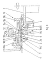
- clamping tables 2 are rotatably mounted on a rotary table 1 in a carousel design.
- the clamping tables 2 are driven by a drive motor 5 via gearwheels 3, 4.
- Holding elements 6, 7, 8 in the form of electromagnets are embedded in the upper side of the clamping table 2.
- the central part 2a of the clamping table 2 is separated from the remaining part of the clamping table 2 by an annular recess 2b.
- the loading station A for a circuit board 9 When the clamping table 2 is located at the first station, the loading station A for a circuit board 9, the circuit board 9 is placed in a pre-adjusted manner with its recess 9a over the central part 2a by means of a transport device (not shown) or by hand on the clamping table 2. Then the electromagnets 6.7 are activated to hold the circuit board 9 in this position. Then the turntable 1 rotates one step until the clamping table 2 reaches the next station, namely the centering station B.
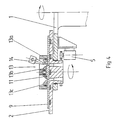
- the centering device 10 for the board 9 and for a molded part 11 to be inserted into the recess 9a of the board 9 above the clamping table 2.
- the centering device 10 has centering elements 10a which are driven synchronously in the direction of the double arrow P1 and which are in a guide 10b can be raised and lowered in the direction of the double arrow P2.
- the position of these centering elements 10a is aligned with the central axis of rotation Z of the clamping table 2.
- the centering elements 10a have, on the underside, spreading fingers 10a 'which can be inserted into the recess 9a of the circuit board 9 and act on the inner edge of the recess 9a. and centering stops 10a ′′, which act on the upper side on the outer edge 11a of the molded part 11, and a tray 10a ′′ ′′ for the molded part 11.
- a holder 12 which can be raised and lowered in the direction of the double arrow P3 and which is equipped with an electromagnet 12a. This holder 12 can be moved radially to the rotary table 1 in the direction of the double arrow P4.
- the electromagnets 6, 7, 8 are first switched off.
- the centering elements 10a are moved together radially.
- the centering device 10 is then lowered so that its spreading fingers 10a 'are located within the recess 9a.
- the spreading fingers 10a 'are then moved apart radially with their synchronous drive.
- the electromagnets 6.7 are switched on again.
- the holder 12 has transported the molded part 11 from a position outside the carousel to a position above the recess 9a and placed it on the support 10a ′′ ′′ of the centering elements 10a.
- the centering elements 10a are moved together radially by their synchronous drive until the centering stops 10a ′′ grip the molded part 11 on the outer edge 11a on all sides and thereby bring them into the desired centered position.
- the holder 12 is then lowered to the molded part 11 and the electromagnet 12a is switched on. After loosening the centering elements 10a, that which is held in place by the holder 12 Molding 11 is raised to above the centering device 10.
- the centering elements 10a are raised in the direction of arrow P2 until the lower ends of the spreading fingers 10a 'are above the upper level of the board 9.
- the spreading fingers 10 can then be moved further radially outward to release the recess 9a.
- the electromagnet 8 is switched off, the molded part 11 is lowered with the holder 12 and inserted into the recess 9a until it rests on the central part 2a of the clamping table 2 which serves as a support and holding plate.
- the electromagnet 8 is then switched on to fix the molded part 9 and the electromagnet 12a is switched off.
- the turntable 1 then switches a further step until the clamping table 2 reaches the welding station C.
- the welding station C comprises a clamping device 13 which is arranged above the clamping table 2 and can be lowered against the circuit board 9 and the molded part 11 and with which the circuit board 9 and the molded part 11 can be clamped.
- the clamping device 13 has in a carrier 13a a freely rotatably mounted central clamping jaw 13b for the molded part 11 and a freely rotatably mounted annular clamping jaw 13c for the plate 9.
- the clamping jaws 13b, 13c are therefore dragged along.
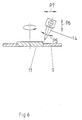
- the clamping jaws 13b, 13c leave an annular gap between them in which the joint lies between the plate 9 and the molded part 11.
- a welding beam device 14 is directed onto this joint.
- the set position of the welding jet device 14 is retained during the rotation of the clamping plate 2.
- the welding beam device 14 can be adjusted in accordance with the degrees of freedom represented by double arrows P5-P7 in FIG.
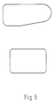
- centering device 10 Although the operation of the centering device 10 is described using the example of a circular recess 9, it goes without saying that the centering device 10 can also be used to align recesses and moldings of different formats. In the case of non-circular shapes, as shown in FIG. 5, it is only necessary to carry out the basic setting for different widths in the case of two pairs of cross-centering centering elements.
Landscapes
- Physics & Mathematics (AREA)
- Optics & Photonics (AREA)
- Engineering & Computer Science (AREA)
- Mechanical Engineering (AREA)
- Plasma & Fusion (AREA)
- Lining Or Joining Of Plastics Or The Like (AREA)
- Arc Welding In General (AREA)
- Butt Welding And Welding Of Specific Article (AREA)
- Laser Beam Processing (AREA)
- Auxiliary Devices For And Details Of Packaging Control (AREA)
- Perforating, Stamping-Out Or Severing By Means Other Than Cutting (AREA)
Applications Claiming Priority (2)
| Application Number | Priority Date | Filing Date | Title |
|---|---|---|---|
| DE4127271A DE4127271C1 (el) | 1991-08-17 | 1991-08-17 | |
| DE4127271 | 1991-08-17 |
Publications (2)
| Publication Number | Publication Date |
|---|---|
| EP0528321A1 EP0528321A1 (de) | 1993-02-24 |
| EP0528321B1 true EP0528321B1 (de) | 1995-02-22 |
Family
ID=6438543
Family Applications (1)
| Application Number | Title | Priority Date | Filing Date |
|---|---|---|---|
| EP92113611A Expired - Lifetime EP0528321B1 (de) | 1991-08-17 | 1992-08-10 | Vorrichtung zum Einsetzen und Einschweissen von flachen Formteilen in Ausnehmungen von Platinen |
Country Status (9)
| Country | Link |
|---|---|
| EP (1) | EP0528321B1 (el) |
| AT (1) | ATE118711T1 (el) |
| CZ (1) | CZ251192A3 (el) |
| DE (1) | DE4127271C1 (el) |
| DK (1) | DK0528321T3 (el) |
| ES (1) | ES2072064T3 (el) |
| GR (1) | GR3015455T3 (el) |
| HU (1) | HUT61920A (el) |
| SK (1) | SK251192A3 (el) |
Cited By (1)
| Publication number | Priority date | Publication date | Assignee | Title |
|---|---|---|---|---|
| DE19636656C1 (de) * | 1996-09-10 | 1997-11-20 | Hoesch Platinen Gmbh | Verfahren zum Herstellen geschweißter Stahlblechplatinen |
Families Citing this family (6)
| Publication number | Priority date | Publication date | Assignee | Title |
|---|---|---|---|---|
| DE4312439C2 (de) * | 1993-04-16 | 1995-02-09 | Ilch Hartmut Dipl Ing Fh | Vorrichtung und Verfahren zum Verschweißen eines Anschweißteils und eines Basisteils |
| FI100317B (fi) * | 1994-05-04 | 1997-11-14 | Vahterus Oy | Ohutlevyjen hitsausmenetelmä ja -laite |
| DE19752095B4 (de) * | 1997-11-25 | 2005-03-10 | Thyssenkrupp Drauz Gmbh | Einrichtung zum Einschieben und Positionieren von mindestens zwei Blechplatinen in eine Laserstrahlschweißmaschine |
| DE102006023872B3 (de) * | 2006-05-19 | 2008-01-17 | Thyssenkrupp Drauz Nothelfer Gmbh | Vorrichtung zum axialen Fügen rotationssymmetrischer Bauteile |
| CN101434006B (zh) * | 2008-11-14 | 2011-05-04 | 深圳市大族激光科技股份有限公司 | 激光焊接工作台 |
| CN106670669B (zh) * | 2017-02-23 | 2017-09-05 | 厦门群协金属构件有限公司 | 一种不锈钢板焊接设备 |
Family Cites Families (4)
| Publication number | Priority date | Publication date | Assignee | Title |
|---|---|---|---|---|
| US2475772A (en) * | 1943-03-31 | 1949-07-12 | Allis Chalmers Mfg Co | Method of blading rotors and other elements |
| US3799007A (en) * | 1972-03-20 | 1974-03-26 | Robertshaw Controls Co | Method and apparatus for welding bellows constructions and the like |
| DE3823509C1 (el) * | 1988-07-12 | 1989-12-07 | Babcock-Bsh Ag Vormals Buettner-Schilde-Haas Ag, 4150 Krefeld, De | |
| US5020716A (en) * | 1989-12-26 | 1991-06-04 | United Technologies Corporation | Integrated brazing fixture for brazing titanium |
-
1991
- 1991-08-17 DE DE4127271A patent/DE4127271C1/de not_active Expired - Fee Related
-
1992
- 1992-08-10 AT AT92113611T patent/ATE118711T1/de not_active IP Right Cessation
- 1992-08-10 ES ES92113611T patent/ES2072064T3/es not_active Expired - Lifetime
- 1992-08-10 DK DK92113611.5T patent/DK0528321T3/da active
- 1992-08-10 EP EP92113611A patent/EP0528321B1/de not_active Expired - Lifetime
- 1992-08-11 HU HU9202613A patent/HUT61920A/hu unknown
- 1992-08-14 CZ CS922511A patent/CZ251192A3/cs unknown
- 1992-08-14 SK SK2511-92A patent/SK251192A3/sk unknown
-
1995
- 1995-03-17 GR GR950400587T patent/GR3015455T3/el unknown
Cited By (1)
| Publication number | Priority date | Publication date | Assignee | Title |
|---|---|---|---|---|
| DE19636656C1 (de) * | 1996-09-10 | 1997-11-20 | Hoesch Platinen Gmbh | Verfahren zum Herstellen geschweißter Stahlblechplatinen |
Also Published As
| Publication number | Publication date |
|---|---|
| ATE118711T1 (de) | 1995-03-15 |
| GR3015455T3 (en) | 1995-06-30 |
| DK0528321T3 (da) | 1995-05-29 |
| ES2072064T3 (es) | 1995-07-01 |
| HUT61920A (en) | 1993-03-29 |
| DE4127271C1 (el) | 1993-04-15 |
| SK251192A3 (en) | 1996-05-08 |
| EP0528321A1 (de) | 1993-02-24 |
| CZ251192A3 (en) | 1993-03-17 |
Similar Documents
| Publication | Publication Date | Title |
|---|---|---|
| AT389837B (de) | Automatische montagemaschine | |
| DE68919655T2 (de) | Verfahren und Gerät zur Herstellung von Teilen eines elektrischen Motors unter Anwendung einer Palette mit abnehmbaren Werkstückhaltern. | |
| DE69304112T2 (de) | Gerät und Verfahren zur Herstellung zweier oder mehrerer verschiedenen Arten geschweisster Paneele | |
| DE69006132T2 (de) | Indexiergerät mit rotierender Bewegung. | |
| DE19831578A1 (de) | Positioniergerät und Positionierverfahren | |
| EP1331059B1 (de) | Vorrichtung zum Spannen von Behältern und Verfahren zum Spannen, Positionieren und Bearbeiten von Behälter,Tonnen, Kesseln, Rohren und dergleichen unter verwendung einer solchen Vorrichtung | |
| EP0528321B1 (de) | Vorrichtung zum Einsetzen und Einschweissen von flachen Formteilen in Ausnehmungen von Platinen | |
| DE69602164T2 (de) | Automatische bohr- und fräsmaschine für glassplatten | |
| EP0873207B1 (de) | Bearbeitungsmaschine | |
| DE19526466C1 (de) | Verfahren zum Schneiden und/oder Verschweißen von Blechen und Bearbeitungsanlage zur Durchführung des Verfahrens | |
| DE69007868T2 (de) | Gerät zum Zusammensetzen, das Stützstifte zur Unterstützung der gedruckten Schaltungsplatte verwendet. | |
| EP1924399B1 (de) | Vorrichtung zum transportieren von werkstückträgern | |
| DE3219459A1 (de) | Automatische foerderanlage zum transportieren von werkstuecken in einer maschinenwerkstatt | |
| DE4339813A1 (de) | Verfahren zum Umsetzen von plattenförmigen Gegenständen, insbes. Leiterplatten, und Vorrichtung zur Durchführung des Verfahrens | |
| EP0566770A1 (de) | Verfahren und Vorrichtung zum Aufteilen von Platten und Bearbeiten der durch das Aufteilen erzeugten Werkstücke | |
| CH665158A5 (de) | Wechselpalette zum einspannen und ausrichten von werkstuecken. | |
| EP0245317B1 (de) | Hochfrequenz-schweissanlage | |
| EP2033735A1 (de) | Kompakter Werkstückwechsler | |
| DE19619231B4 (de) | Einrichtung zum Transportieren, Spannen und Laserstrahlschweißen von mindestens zwei Blechplatinen | |
| DE3416858A1 (de) | Zentrier- und spannvorrichtung fuer werkstuecktraeger-paletten einer transfermaschine | |
| EP0362833A2 (de) | Holzbearbeitungsmaschine, insbesondere Kehlmaschine | |
| EP0193789B1 (de) | Verfahren zum Eckenstossen von planen, rechteckigen Scheiben | |
| DE3041376A1 (de) | Vorrichtung zum transportieren oder zwischenspeichern von werkstuecken | |
| DE69603844T2 (de) | Vorrichtung zur herstellung von mehrschichtschaltungen | |
| DE3302273C1 (de) | Montageeinrichtung mit einem kontinuierlich bewegten Transferband |
Legal Events
| Date | Code | Title | Description |
|---|---|---|---|
| PUAI | Public reference made under article 153(3) epc to a published international application that has entered the european phase |
Free format text: ORIGINAL CODE: 0009012 |
|
| AK | Designated contracting states |
Kind code of ref document: A1 Designated state(s): AT BE CH DE DK ES FR GB GR IE IT LI LU MC NL PT SE |
|
| 17P | Request for examination filed |
Effective date: 19930521 |
|
| 17Q | First examination report despatched |
Effective date: 19940620 |
|
| RBV | Designated contracting states (corrected) |
Designated state(s): AT BE CH DK ES FR GB GR IE IT LI LU MC NL PT SE |
|
| REG | Reference to a national code |
Ref country code: DE Ref legal event code: 8566 |
|
| GRAA | (expected) grant |
Free format text: ORIGINAL CODE: 0009210 |
|
| AK | Designated contracting states |
Kind code of ref document: B1 Designated state(s): AT BE CH DK ES FR GB GR IE IT LI LU MC NL PT SE |
|
| REF | Corresponds to: |
Ref document number: 118711 Country of ref document: AT Date of ref document: 19950315 Kind code of ref document: T |
|
| REG | Reference to a national code |
Ref country code: IE Ref legal event code: FG4D Free format text: 63055 |
|
| GBT | Gb: translation of ep patent filed (gb section 77(6)(a)/1977) |
Effective date: 19950216 |
|
| ITF | It: translation for a ep patent filed | ||
| ET | Fr: translation filed | ||
| REG | Reference to a national code |
Ref country code: DK Ref legal event code: T3 |
|
| REG | Reference to a national code |
Ref country code: GR Ref legal event code: FG4A Free format text: 3015455 |
|
| REG | Reference to a national code |
Ref country code: ES Ref legal event code: FG2A Ref document number: 2072064 Country of ref document: ES Kind code of ref document: T3 |
|
| PLBE | No opposition filed within time limit |
Free format text: ORIGINAL CODE: 0009261 |
|
| STAA | Information on the status of an ep patent application or granted ep patent |
Free format text: STATUS: NO OPPOSITION FILED WITHIN TIME LIMIT |
|
| 26N | No opposition filed | ||
| PGFP | Annual fee paid to national office [announced via postgrant information from national office to epo] |
Ref country code: LU Payment date: 19960701 Year of fee payment: 5 Ref country code: IE Payment date: 19960701 Year of fee payment: 5 |
|
| PGFP | Annual fee paid to national office [announced via postgrant information from national office to epo] |
Ref country code: GR Payment date: 19960703 Year of fee payment: 5 |
|
| PGFP | Annual fee paid to national office [announced via postgrant information from national office to epo] |
Ref country code: PT Payment date: 19960708 Year of fee payment: 5 |
|
| PGFP | Annual fee paid to national office [announced via postgrant information from national office to epo] |
Ref country code: FR Payment date: 19960724 Year of fee payment: 5 |
|
| PGFP | Annual fee paid to national office [announced via postgrant information from national office to epo] |
Ref country code: GB Payment date: 19960725 Year of fee payment: 5 Ref country code: CH Payment date: 19960725 Year of fee payment: 5 |
|
| PGFP | Annual fee paid to national office [announced via postgrant information from national office to epo] |
Ref country code: SE Payment date: 19960729 Year of fee payment: 5 Ref country code: AT Payment date: 19960729 Year of fee payment: 5 |
|
| PGFP | Annual fee paid to national office [announced via postgrant information from national office to epo] |
Ref country code: DK Payment date: 19960730 Year of fee payment: 5 |
|
| PGFP | Annual fee paid to national office [announced via postgrant information from national office to epo] |
Ref country code: BE Payment date: 19960812 Year of fee payment: 5 |
|
| PGFP | Annual fee paid to national office [announced via postgrant information from national office to epo] |
Ref country code: ES Payment date: 19960816 Year of fee payment: 5 |
|
| PGFP | Annual fee paid to national office [announced via postgrant information from national office to epo] |
Ref country code: MC Payment date: 19960823 Year of fee payment: 5 |
|
| PGFP | Annual fee paid to national office [announced via postgrant information from national office to epo] |
Ref country code: NL Payment date: 19960830 Year of fee payment: 5 |
|
| PG25 | Lapsed in a contracting state [announced via postgrant information from national office to epo] |
Ref country code: LU Free format text: LAPSE BECAUSE OF NON-PAYMENT OF DUE FEES Effective date: 19970810 Ref country code: IE Free format text: LAPSE BECAUSE OF NON-PAYMENT OF DUE FEES Effective date: 19970810 Ref country code: GB Free format text: LAPSE BECAUSE OF NON-PAYMENT OF DUE FEES Effective date: 19970810 Ref country code: DK Free format text: LAPSE BECAUSE OF NON-PAYMENT OF DUE FEES Effective date: 19970810 Ref country code: AT Free format text: LAPSE BECAUSE OF NON-PAYMENT OF DUE FEES Effective date: 19970810 |
|
| REG | Reference to a national code |
Ref country code: DK Ref legal event code: EBP |
|
| PG25 | Lapsed in a contracting state [announced via postgrant information from national office to epo] |
Ref country code: SE Free format text: LAPSE BECAUSE OF NON-PAYMENT OF DUE FEES Effective date: 19970811 Ref country code: ES Free format text: LAPSE BECAUSE OF NON-PAYMENT OF DUE FEES Effective date: 19970811 |
|
| PG25 | Lapsed in a contracting state [announced via postgrant information from national office to epo] |
Ref country code: LI Free format text: LAPSE BECAUSE OF NON-PAYMENT OF DUE FEES Effective date: 19970831 Ref country code: GR Free format text: LAPSE BECAUSE OF NON-PAYMENT OF DUE FEES Effective date: 19970831 Ref country code: CH Free format text: LAPSE BECAUSE OF NON-PAYMENT OF DUE FEES Effective date: 19970831 Ref country code: BE Free format text: LAPSE BECAUSE OF NON-PAYMENT OF DUE FEES Effective date: 19970831 |
|
| BERE | Be: lapsed |
Owner name: THYSSEN STAHL A.G. Effective date: 19970831 |
|
| PG25 | Lapsed in a contracting state [announced via postgrant information from national office to epo] |
Ref country code: PT Free format text: LAPSE BECAUSE OF NON-PAYMENT OF DUE FEES Effective date: 19980228 Ref country code: MC Free format text: LAPSE BECAUSE OF NON-PAYMENT OF DUE FEES Effective date: 19980228 |
|
| PG25 | Lapsed in a contracting state [announced via postgrant information from national office to epo] |
Ref country code: NL Free format text: LAPSE BECAUSE OF NON-PAYMENT OF DUE FEES Effective date: 19980301 |
|
| GBPC | Gb: european patent ceased through non-payment of renewal fee |
Effective date: 19970810 |
|
| REG | Reference to a national code |
Ref country code: CH Ref legal event code: PL |
|
| PG25 | Lapsed in a contracting state [announced via postgrant information from national office to epo] |
Ref country code: FR Free format text: LAPSE BECAUSE OF NON-PAYMENT OF DUE FEES Effective date: 19980430 |
|
| EUG | Se: european patent has lapsed |
Ref document number: 92113611.5 |
|
| NLV4 | Nl: lapsed or anulled due to non-payment of the annual fee |
Effective date: 19980301 |
|
| REG | Reference to a national code |
Ref country code: FR Ref legal event code: ST |
|
| REG | Reference to a national code |
Ref country code: PT Ref legal event code: MM4A Free format text: LAPSE DUE TO NON-PAYMENT OF FEES Effective date: 19980228 |
|
| REG | Reference to a national code |
Ref country code: ES Ref legal event code: FD2A Effective date: 19980910 |
|
| PG25 | Lapsed in a contracting state [announced via postgrant information from national office to epo] |
Ref country code: IT Free format text: LAPSE BECAUSE OF NON-PAYMENT OF DUE FEES;WARNING: LAPSES OF ITALIAN PATENTS WITH EFFECTIVE DATE BEFORE 2007 MAY HAVE OCCURRED AT ANY TIME BEFORE 2007. THE CORRECT EFFECTIVE DATE MAY BE DIFFERENT FROM THE ONE RECORDED. Effective date: 20050810 |