EP0528321B1 - Apparatus for mounting and welding flat articles in plate holes - Google Patents
Apparatus for mounting and welding flat articles in plate holes Download PDFInfo
- Publication number
- EP0528321B1 EP0528321B1 EP92113611A EP92113611A EP0528321B1 EP 0528321 B1 EP0528321 B1 EP 0528321B1 EP 92113611 A EP92113611 A EP 92113611A EP 92113611 A EP92113611 A EP 92113611A EP 0528321 B1 EP0528321 B1 EP 0528321B1
- Authority
- EP
- European Patent Office
- Prior art keywords
- plate
- clamping table
- shaped part
- centring
- welding
- Prior art date
- Legal status (The legal status is an assumption and is not a legal conclusion. Google has not performed a legal analysis and makes no representation as to the accuracy of the status listed.)
- Expired - Lifetime
Links
Images


Classifications
-
- B—PERFORMING OPERATIONS; TRANSPORTING
- B23—MACHINE TOOLS; METAL-WORKING NOT OTHERWISE PROVIDED FOR
- B23K—SOLDERING OR UNSOLDERING; WELDING; CLADDING OR PLATING BY SOLDERING OR WELDING; CUTTING BY APPLYING HEAT LOCALLY, e.g. FLAME CUTTING; WORKING BY LASER BEAM
- B23K26/00—Working by laser beam, e.g. welding, cutting or boring
- B23K26/20—Bonding
- B23K26/21—Bonding by welding
- B23K26/24—Seam welding
-
- B—PERFORMING OPERATIONS; TRANSPORTING
- B23—MACHINE TOOLS; METAL-WORKING NOT OTHERWISE PROVIDED FOR
- B23K—SOLDERING OR UNSOLDERING; WELDING; CLADDING OR PLATING BY SOLDERING OR WELDING; CUTTING BY APPLYING HEAT LOCALLY, e.g. FLAME CUTTING; WORKING BY LASER BEAM
- B23K26/00—Working by laser beam, e.g. welding, cutting or boring
- B23K26/08—Devices involving relative movement between laser beam and workpiece
- B23K26/0823—Devices involving rotation of the workpiece
-
- B—PERFORMING OPERATIONS; TRANSPORTING
- B23—MACHINE TOOLS; METAL-WORKING NOT OTHERWISE PROVIDED FOR
- B23K—SOLDERING OR UNSOLDERING; WELDING; CLADDING OR PLATING BY SOLDERING OR WELDING; CUTTING BY APPLYING HEAT LOCALLY, e.g. FLAME CUTTING; WORKING BY LASER BEAM
- B23K37/00—Auxiliary devices or processes, not specially adapted to a procedure covered by only one of the preceding main groups
- B23K37/04—Auxiliary devices or processes, not specially adapted to a procedure covered by only one of the preceding main groups for holding or positioning work
Definitions
- the invention relates to a device for inserting and welding flat molded parts into recesses in circuit boards, with which the molded parts can be inserted without problems even with very small gap widths.
- a simple molded part can be inserted into the recess of the board without any problems, because the combined centering device is aligned with the recess and the orientation of the molded part takes place as a function of this orientation. This creates a direct relationship between the recess in the clamped circuit board and the molded part held by the holder. With the board fixed, the welding beam can then be guided exactly along the joint.
- a support and Holding plate is arranged in the area of the centering elements and essentially at the same level as the top of the clamping table. This support and holding plate allows the Release of the molded part by the holder on the top without the fitting position of the molded part in the circuit board suffering as a result.
- the clamping table is preferably rotatably mounted. This configuration allows the welding device to be positioned in a fixed position. "Fixed” is also understood to mean an arrangement of the welding device which allows a pivoting movement in order to adapt to the position of the weld joint, which is particularly necessary if the weld joint is not concentric with the axis of rotation of the clamping table.
- An easily releasable and continuously acting fixation for the board and the molded part consists in that the holding elements and / or the holder and / or the support and holding plate can be activated electromagnetically. Of course, this type of activation only works with ferromagnetic material of the board and the molded part.
- a plurality of similar clamping tables in the manner of a carousel are arranged on a turntable and can be moved successively to different stationary stations, specifically a loading station for the board, a centering station for the board and the molded part, the centering device, a welding station and a discharge station.
- different work can be carried out in parallel at the different stations in the sense of increased output.
- a clamping device can be arranged, in particular at the welding station, which detects the circuit board and the fitting on the upper side and cooperates with the lower-side clamping table and is carried along by the rotating clamping table.
- clamping tables 2 are rotatably mounted on a rotary table 1 in a carousel design.
- the clamping tables 2 are driven by a drive motor 5 via gearwheels 3, 4.
- Holding elements 6, 7, 8 in the form of electromagnets are embedded in the upper side of the clamping table 2.
- the central part 2a of the clamping table 2 is separated from the remaining part of the clamping table 2 by an annular recess 2b.
- the loading station A for a circuit board 9 When the clamping table 2 is located at the first station, the loading station A for a circuit board 9, the circuit board 9 is placed in a pre-adjusted manner with its recess 9a over the central part 2a by means of a transport device (not shown) or by hand on the clamping table 2. Then the electromagnets 6.7 are activated to hold the circuit board 9 in this position. Then the turntable 1 rotates one step until the clamping table 2 reaches the next station, namely the centering station B.
- the centering device 10 for the board 9 and for a molded part 11 to be inserted into the recess 9a of the board 9 above the clamping table 2.
- the centering device 10 has centering elements 10a which are driven synchronously in the direction of the double arrow P1 and which are in a guide 10b can be raised and lowered in the direction of the double arrow P2.
- the position of these centering elements 10a is aligned with the central axis of rotation Z of the clamping table 2.
- the centering elements 10a have, on the underside, spreading fingers 10a 'which can be inserted into the recess 9a of the circuit board 9 and act on the inner edge of the recess 9a. and centering stops 10a ′′, which act on the upper side on the outer edge 11a of the molded part 11, and a tray 10a ′′ ′′ for the molded part 11.
- a holder 12 which can be raised and lowered in the direction of the double arrow P3 and which is equipped with an electromagnet 12a. This holder 12 can be moved radially to the rotary table 1 in the direction of the double arrow P4.
- the electromagnets 6, 7, 8 are first switched off.
- the centering elements 10a are moved together radially.
- the centering device 10 is then lowered so that its spreading fingers 10a 'are located within the recess 9a.
- the spreading fingers 10a 'are then moved apart radially with their synchronous drive.
- the electromagnets 6.7 are switched on again.
- the holder 12 has transported the molded part 11 from a position outside the carousel to a position above the recess 9a and placed it on the support 10a ′′ ′′ of the centering elements 10a.
- the centering elements 10a are moved together radially by their synchronous drive until the centering stops 10a ′′ grip the molded part 11 on the outer edge 11a on all sides and thereby bring them into the desired centered position.
- the holder 12 is then lowered to the molded part 11 and the electromagnet 12a is switched on. After loosening the centering elements 10a, that which is held in place by the holder 12 Molding 11 is raised to above the centering device 10.
- the centering elements 10a are raised in the direction of arrow P2 until the lower ends of the spreading fingers 10a 'are above the upper level of the board 9.
- the spreading fingers 10 can then be moved further radially outward to release the recess 9a.
- the electromagnet 8 is switched off, the molded part 11 is lowered with the holder 12 and inserted into the recess 9a until it rests on the central part 2a of the clamping table 2 which serves as a support and holding plate.
- the electromagnet 8 is then switched on to fix the molded part 9 and the electromagnet 12a is switched off.
- the turntable 1 then switches a further step until the clamping table 2 reaches the welding station C.
- the welding station C comprises a clamping device 13 which is arranged above the clamping table 2 and can be lowered against the circuit board 9 and the molded part 11 and with which the circuit board 9 and the molded part 11 can be clamped.
- the clamping device 13 has in a carrier 13a a freely rotatably mounted central clamping jaw 13b for the molded part 11 and a freely rotatably mounted annular clamping jaw 13c for the plate 9.
- the clamping jaws 13b, 13c are therefore dragged along.
- the clamping jaws 13b, 13c leave an annular gap between them in which the joint lies between the plate 9 and the molded part 11.
- a welding beam device 14 is directed onto this joint.
- the set position of the welding jet device 14 is retained during the rotation of the clamping plate 2.
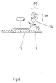
- the welding beam device 14 can be adjusted in accordance with the degrees of freedom represented by double arrows P5-P7 in FIG.
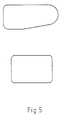
- centering device 10 Although the operation of the centering device 10 is described using the example of a circular recess 9, it goes without saying that the centering device 10 can also be used to align recesses and moldings of different formats. In the case of non-circular shapes, as shown in FIG. 5, it is only necessary to carry out the basic setting for different widths in the case of two pairs of cross-centering centering elements.
Abstract
Description
Um bei Bauteilen aus Blech unter Berücksichtigung ihrer örtlich unterschiedlichen Beanspruchung zu einer optimalen Auslegung zu kommen, ist es bekannt, in Platinen ein flaches Formteil aus einem anderen Material oder mit unterschiedlicher Dicke einzuschweißen. Dazu werden in eine Platine eine Ausnehmung und ein dazu passendes flaches Formteil geschnitten. Für verschiedene Schweißverfahren, wie Laserschweißen, wird gefordert, daß der Schweißspalt höchstens eine Breite ![]()
![]()
![]()
![]()
Die Erfindung betrifft eine Vorrichtung zum Einsetzen und Einschweißen von flachen Formteilen in Ausnehmungen von Platinen, mit der auch bei sehr kleinen Spaltbreiten das Einsetzen der Formteile problemlos möglich ist.The invention relates to a device for inserting and welding flat molded parts into recesses in circuit boards, with which the molded parts can be inserted without problems even with very small gap widths.
Die erfindungsgemäße Vorrichtung besteht aus:
- a) Einem Spanntisch mit Halteelementen zum Festlegen der Platine,
- b) einer über dem Spanntisch heb- und senkbar angeordneten, kombinierten Zentriervorrichtung für die Platine und das Formteil mit synchron angetriebenen Zentrierelementen, die unterseitig in einer Ausnehmung der Platine einführbare, am Innenrand der Ausnehmung angreifende Spreizfinger und oberseitig am Außenrand des Formteils angreifende Zentrieranschläge aufweisen,
- c) einem im Bereich der Zentrierelemente über dem Spanntisch heb- und senkbar angeordneten, an der Oberseite des Formteils angreifenden Halter, und
- d) einer relativ zur Platine mit dem eingesetzten Formteil und längs der von Platine und Formteilen gebildeten Fuge verfahrbaren Schweißeinrichtung.
- a) a clamping table with holding elements for fixing the board,
- b) a combined centering device for the board and the molded part, which can be raised and lowered above the clamping table, with synchronously driven centering elements which have spreading fingers which can be inserted into a recess of the board on the underside and which engage on the inner edge of the recess and on the upper side which engage on the outer edge of the molded part,
- c) a holder which can be raised and lowered in the region of the centering elements above the clamping table and which engages on the upper side of the molded part, and
- d) a welding device which can be moved relative to the circuit board with the molded part used and along the joint formed by the circuit board and molded parts.
Mit der erfindungsgmäßen Vorrichtung läßt sich problemlos ein einfaches Formteil in die Ausnehmung der Platine einsetzen, weil die kombinierte Zentriervorrichtung an der Ausnehmung ausgerichtet und in Abhängigkeit von dieser Ausrichtung die Ausrichtung des Formteils erfolgt. Damit ist ein direkter Bezug zwischen der Ausnehmung in der festgespannten Platine und dem vom Halter festgehaltenen Formteil hergestellt. Bei festliegender Platine läßt sich dann der Schweißstrahl exakt längs der Fuge führen.With the device according to the invention, a simple molded part can be inserted into the recess of the board without any problems, because the combined centering device is aligned with the recess and the orientation of the molded part takes place as a function of this orientation. This creates a direct relationship between the recess in the clamped circuit board and the molded part held by the holder. With the board fixed, the welding beam can then be guided exactly along the joint.
Um die Zugänglichkeit zu der Platine mit dem mittels des Halters eingesetzten Formteils von oben zu erleichtern, ist nach einer Ausgestaltung der Erfindung vorgesehen, daß im Bereich der Zentrierelemente und im wesentlichen niveaugleich mit der Oberseite des Spanntisches eine an der Unterseite des Formteils angreifende Stütz- und Halteplatte angeordnet ist. Diese Stütz- und Halteplatte erlaubt die Freigabe des Formteils durch den oberseitigen Halter, ohne daß darunter die passungsgerechte Lage des Formteils in der Platine leidet.In order to facilitate access to the board with the molded part inserted by means of the holder from above, it is provided according to one embodiment of the invention that in the area of the centering elements and essentially at the same level as the top of the clamping table, a support and Holding plate is arranged. This support and holding plate allows the Release of the molded part by the holder on the top without the fitting position of the molded part in the circuit board suffering as a result.
Um den Schweißstrahl längs der Fuge entlang fahren zu können, ist vorzugsweise der Spanntisch drehbar gelagert. Diese Ausgestaltung erlaubt eine ortsfeste Positionierung der Schweißvorrichtung. Unter "ortsfest" wird auch noch eine Anordnung der Schweißvorrichtung verstanden, die eine Schwenkbewegung erlaubt, um sich der Lage der Schweißfuge anzupassen, was vor allem dann notwendig ist, wenn die Schweißfuge nicht konzentrisch zur Drehachse des Spanntisches verläuft.In order to be able to drive the welding beam along the joint, the clamping table is preferably rotatably mounted. This configuration allows the welding device to be positioned in a fixed position. "Fixed" is also understood to mean an arrangement of the welding device which allows a pivoting movement in order to adapt to the position of the weld joint, which is particularly necessary if the weld joint is not concentric with the axis of rotation of the clamping table.
Eine leicht lösbare und stufenlos wirkende Fixierung für die Platine und das Formteil besteht darin, daß die Halteelemente und/oder der Halter und/oder die Stütz- und Halteplatte elektromagnetisch aktivierbar sind. Diese Art der Aktivierung funktioniert natürlich nur bei ferromagnetischem Material der Platine und des Formteils.An easily releasable and continuously acting fixation for the board and the molded part consists in that the holding elements and / or the holder and / or the support and holding plate can be activated electromagnetically. Of course, this type of activation only works with ferromagnetic material of the board and the molded part.
Nach einer bevorzugten Ausgestaltung der Erfindung sind mehrere gleichartige Spanntische nach Art eines Karussells auf einem Drehtisch angeordnet und nacheinander schrittweise an verschiedene ortsfeste Stationen bewegbar, und zwar eine Aufgabestation für die Platine, eine die Zentriervorrichtung umfassenden Zentrierstation für die Platine und das Formteil, eine Schweißstation und eine Austragstation. Bei dieser Art der Ausgestaltung der erfindungsgemäßen Vorrichtung lassen sich an den verschiedenen Stationen verschiedene Arbeiten parallel zueinander im Sinne eines erhöhten Ausstoßes ausführen.According to a preferred embodiment of the invention, a plurality of similar clamping tables in the manner of a carousel are arranged on a turntable and can be moved successively to different stationary stations, specifically a loading station for the board, a centering station for the board and the molded part, the centering device, a welding station and a discharge station. With this type of design of the device according to the invention, different work can be carried out in parallel at the different stations in the sense of increased output.
Um eine mögliche Verformung der Platine beim Einschweißen des Formteils infolge möglicherweise entstehender Wärmespannungen zu vermeiden, kann insbesondere an der Schweißstation eine oberseitig die Platine und das Formstück erfassende und mit dem unterseitigen Spanntisch klemmend zusammenwirkende, vom sich drehenden Spanntisch mitgeschleppten Klemmvorrichtung angeordnet sein.A possible deformation of the board when welding the molded part as a result of possibly arising To avoid thermal stresses, a clamping device can be arranged, in particular at the welding station, which detects the circuit board and the fitting on the upper side and cooperates with the lower-side clamping table and is carried along by the rotating clamping table.
Im folgenden wird die Erfindung anhand einer ein Ausführungsbeispiel schematisch darstellenden Zeichnung näher erläutert. Im einzelnen zeigen:
- Fig. 1a
- eine Platine mit einer kreisförmigen Ausnehmung im Querschnitt und in Aufsicht,
- Fig. 1b
- ein flaches kreisförmiges Formteil im Querschnitt und in Aufsicht,
- Fig. 1c
- die Platine gemäß Fig. 1a mit eingeschweißtem Formteil gemäß Fig. 1b im Querschnitt und in Aufsicht,
- Fig. 2
- eine Vorrichtung zum Einsetzen und Schweißen von flachen Formteilen in Ausnehmungen von Platinen in Karussellbauart mit einer Aufgabestation, einer Zentrierstation, einer Schweißstation und einer Austragestation in Aufsicht,
- Fig. 3
- die Vorrichtung gemäß Fig. 2 im Axialschnitt an der Zentrierstation,
- Fig. 4
- die Vorrichtung gemäß Fig. 2 im Axialschnitt an der Schweißstation,
- Fig. 5
- verschiedene Formen von einzuschweißenden Formteilen in Aufsicht
und - Fig. 6
- eine Schweißeinrichtung in Schweißposition an einer Platine mit eingesetztem Formteil im Axialschnitt.
- Fig. 1a
- a circuit board with a circular recess in cross section and in supervision,
- Fig. 1b
- a flat circular shaped part in cross section and in supervision,
- Fig. 1c
- 1a with a welded-in molded part according to FIG. 1b in cross section and in supervision,
- Fig. 2
- a device for inserting and welding flat molded parts in recesses of blanks of carousel type with a feed station, a centering station, a welding station and a discharge station under supervision,
- Fig. 3
- 2 in axial section at the centering station,
- Fig. 4
- 2 in axial section at the welding station,
- Fig. 5
- various forms of molded parts to be welded in supervision
and - Fig. 6
- a welding device in the welding position on a circuit board with an inserted molded part in axial section.
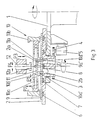
Auf einem Drehtisch 1 sind in Karussellbauart vier gleichartige Spanntische 2 drehbar gelagert. Angetrieben werden die Spanntische 2 über Zahnräder 3,4 von einem Antriebsmotor 5. In der Oberseite des Spanntisches 2 sind Halteelemente 6,7,8 in Form von Elektromagneten eingelagert. Der mittige Teil 2a des Spanntisches 2 ist von dem übrigen Teil des Spanntisches 2 durch eine ringförmige Ausnehmung 2b getrennt.Four similar clamping tables 2 are rotatably mounted on a rotary table 1 in a carousel design. The clamping tables 2 are driven by a
Wenn sich der Spanntisch 2 an der ersten Station, der Aufgabestation A für eine Platine 9 befindet, wird die Platine 9 mittels einer nicht dargestellten Transportvorrichtung oder auch von Hand auf den Spanntisch 2 mit ihrer Ausnehmung 9a über dem mittigen Teil 2a vorjustiert abgelegt. Dann werden die Elektromagnete 6,7 aktiviert, um die Platine 9 in dieser Position festzuhalten. Danach dreht der Drehtisch 1 um einen Schritt, bis daß der Spanntisch 2 die nächste Station, und zwar die Zentrierstation B, erreicht.When the clamping table 2 is located at the first station, the loading station A for a
In dieser Station befindet sich über dem Spanntisch 2 eine kombinierte Zentriervorrichtung 10 für die Platine 9 und für ein in die Ausnehmung 9a der Platine 9 einzusetzendes Formteil 11. Die Zentriervorrichtung 10 weist in Richtung des Doppelpfeils P1 synchron angetriebene Zentrierelemente 10a auf, die in einer Führung 10b in Richtung des Doppelpfeils P2 heb- und senkbar sind. Die Position dieser Zentrierelemente 10a ist an der zentralen Drehachse Z des Spanntisches 2 ausgerichtet. Die Zentrierelemente 10a weisen unterseitig in die Ausnehmung 9a der Platine 9 einführbare, am Innenrand der Ausnehmung 9a angreifende Spreizfinger 10a' und oberseitig am Außenrand 11a des Formteils 11 angreifende Zentrieranschläge 10a'' sowie eine Ablage 10a''' für das Formteil 11 auf.In this station there is a combined centering
Über dem Spanntisch 2 und oberhalb der Zentriervorrichtung 10 befindet sich ein in Richtung des Doppelpfeils P3 heb- und senkbarer Halter 12, der mit einem Elektromagneten 12a bestückt ist. Dieser Halter 12 ist in Richtung des Doppelpfeils P4 radial zum Drehtisch 1 verfahrbar.Above the clamping table 2 and above the centering
Um einerseits die Platine 9 auf dem Spanntisch 2 zu zentrieren und andererseits das Formteil 11 in die Ausnehmung 9a der Platine 9 einzusetzen, werden zunächst die Elektromagnete 6,7,8 abgeschaltet. Die Zentrierelemente 10a werden radial zusammengefahren. Die Zentriervorrichtung 10 wird dann abgesenkt, so daß deren Spreizfinger 10a' sich innerhalb der Ausnehmung 9a befinden. Anschließend werden die Spreizfinger 10a' mit ihrem synchronen Antrieb radial auseinandergefahren. Dabei stoßen die Spreizfinger 10a' an den Innenrand 9a' der Ausnehmung 9a an und verschieben die Platine 9 in die Zentrierposition. Bei noch haltenden Spreizfingern 10a' werden die Elektromagnete 6,7 wieder eingeschaltet.In order to center the
In der Zwischenzeit hat der Halter 12 aus einer Position außerhalb des Karussells das Formteil 11 in eine Position oberhalb der Ausnehmung 9a transportiert und auf die Auflage 10a''' der Zentrierelemente 10a abgelegt. Durch ihren synchronen Antrieb werden die Zentrierelemente 10a radial zusammengefahren, bis daß die Zentrieranschläge 10a'' das Formteil 11 am Außenrand 11a allseitig erfassen und dadurch in die gewünschte zentrierte Position bringen. Danach wird der Halter 12 bis auf das Formteil 11 abgesenkt und der Elektromagnet 12a eingeschaltet. Nach Lösen der Zentrierelemente 10a wird das vom Halter 12 festgehaltene Formteil 11 bis über die Zentriervorrichtung 10 angehoben. Die Zentrierelemente 10a werden in Richtung des Pfeils P2 nach oben hochgefahren, bis daß die unteren Enden der Spreizfinger 10a' über dem oberen Niveau der Platine 9 sich befinden. Dann können die Spreizfinger 10 zur Freigabe der Ausnehmung 9a weiter radial nach außen bewegt werden. Bei ausgeschaltetem Elektromagneten 8 wird mit dem Halter 12 das Formteil 11 abgesenkt und in die Ausnehmung 9a eingesetzt, bis daß es auf dem als Stütz- und Halteplatte dienenden mittleren Teil 2a des Spanntisches 2 aufliegt. Der Elektromagnet 8 wird dann zur Fixierung des Formteils 9 eingeschaltet und der Elektromagnet 12a ausgeschaltet. Mit dem Abheben des Halters 12 ist der Zentrier- und Einsetzvorgang beendet. Der Drehtisch 1 schaltet dann einen weiteren Schritt weiter, bis daß der Spanntisch 2 die Schweißstation C erreicht.In the meantime, the
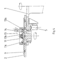
Die Schweißstation C umfaßt eine über dem Spanntisch 2 angeordnete, gegen die Platine 9 und das Formteil 11 absenkbare Klemmvorrichtung 13, mit der die Platine 9 und das Formteil 11 festgeklemmt werden können. Die Klemmvorrichtung 13 weist in einem Träger 13a einen frei drehbar gelagerten mittleren Klemmbacken 13b für das Formteil 11 und eine frei drehbar gelagerte ringförmige Klemmbacke 13c für die Platine 9 auf. Bei angetriebenem Spanntisch 2 werden deshalb die Klemmbacken 13b,13c mitgeschleppt. Die Klemmbacken 13b,13c lassen zwischen sich einen Ringspalt frei, in dem die Fuge zwischen der Platine 9 und dem Formteil 11 liegt. Auf diese Fuge ist eine Schweißstrahleinrichtung 14 gerichtet. Bei kreisförmiger Fuge bleibt die eingestellte Position der Schweißstrahleinrichtung 14 während der Drehung der Spannplatte 2 erhalten. Sofern jedoch andersformatige Schweißfugen, wie in Figur 5 in der Mitte und unten dargestellt sind, ist es notwendig, die Schweißstrahleinrichtung 14 entsprechend der in Figur 6 durch Doppelpfeile P5-P7 dargestellten Freiheitsgrade zu verstellen.The welding station C comprises a
Obgleich die Arbeitsweise der Zentriervorrichtung 10 am Beispiel einer kreisförmigen Ausnehmung 9 beschrieben ist, versteht es sich, daß mit der Zentriervorrichtung 10 auch andersformatige Ausnehmungen und Formteile ausgerichtet werden können. Bei nicht kreisförmigen Formen, wie sie in Figur 5 dargestellt sind, ist es lediglich erforderlich, bei zwei Paar kreuzweise gegenüberliegenden Zentrierelementen die Grundeinstellung für unterschiedliche Weiten vorzunehmen.Although the operation of the centering
Claims (6)
- An apparatus for the insertion and welding of flat shaped parts (11) in recesses (9a) in plates (9), comprising:a) a clamping table (2) having retaining elements (6, 7, 8) for securing the plate (9) in position,b) a combined centring device (10), disposed vertically adjustably above the clamping table (2), for the plate (9) and the shaped part (11) and having synchronously driven centring elements (10a) whose undersides have expanding fingers (10a') which can be introduced into the recess (9a) in the plate (9) and engage with the inner edge (9a') of the recess (9a), and whose top sides have centring stops (10a'') engaging with the outer edge (11a) of the shaped part (11),c) a holder (12) which is disposed vertically adjustably over the clamping table (2) in the zone of the centring elements (10a) and which engages with the top side of the shaped part (11), andd) a welding device (14) which can be moved in relation to the plate (9) with the inserted shaped part (11) and along the joint formed by the plate (9) and the shaped part (11).
- An apparatus according to claim 1, characterized in that a supporting and retaining plate (2a) engaging with the underside of the shaped part (11) is disclosed in the zone of the centring elements (10a) and substantially at the same level as the top side of the clamping table (2).
- An apparatus according to claims 1 or 2, characterized in that the clamping table (2) is rotatable.
- An apparatus according to one of claims 1 to 3, characterized in that the retaining elements (6, 7) and/or the holder (12) and/or the supporting and retaining plate (2a) can be activated electromagnetically.
- An apparatus according to one of claims 1 to 4, characterized in that a number of identical clamping tables (2) are arranged carrousel-fashion on a rotary table (1) and can be moved successively in steps to different fixed stations (A, B, C, D), namely a feed station (A) for the plate (9), a centring station (B) comprising the centring device (10) for the plate (9) and the shaped part (11), a welding station (C) and a delivery station (D).
- An apparatus according to one of claims 1 to 5, characterized in that more particularly at the welding station (C) a clamping device (13b, 13c) is disposed which is entrained by the rotating clamping table (2) and which clampingly cooperates with the underside clamping table (2) and seizes the plate (9) and the shaped part (11) at the top side.
Applications Claiming Priority (2)
| Application Number | Priority Date | Filing Date | Title |
|---|---|---|---|
| DE4127271 | 1991-08-17 | ||
| DE4127271A DE4127271C1 (en) | 1991-08-17 | 1991-08-17 |
Publications (2)
| Publication Number | Publication Date |
|---|---|
| EP0528321A1 EP0528321A1 (en) | 1993-02-24 |
| EP0528321B1 true EP0528321B1 (en) | 1995-02-22 |
Family
ID=6438543
Family Applications (1)
| Application Number | Title | Priority Date | Filing Date |
|---|---|---|---|
| EP92113611A Expired - Lifetime EP0528321B1 (en) | 1991-08-17 | 1992-08-10 | Apparatus for mounting and welding flat articles in plate holes |
Country Status (9)
| Country | Link |
|---|---|
| EP (1) | EP0528321B1 (en) |
| AT (1) | ATE118711T1 (en) |
| CZ (1) | CZ251192A3 (en) |
| DE (1) | DE4127271C1 (en) |
| DK (1) | DK0528321T3 (en) |
| ES (1) | ES2072064T3 (en) |
| GR (1) | GR3015455T3 (en) |
| HU (1) | HUT61920A (en) |
| SK (1) | SK251192A3 (en) |
Cited By (1)
| Publication number | Priority date | Publication date | Assignee | Title |
|---|---|---|---|---|
| DE19636656C1 (en) * | 1996-09-10 | 1997-11-20 | Hoesch Platinen Gmbh | Method of manufacturing welded steel plate |
Families Citing this family (6)
| Publication number | Priority date | Publication date | Assignee | Title |
|---|---|---|---|---|
| DE4312439C2 (en) * | 1993-04-16 | 1995-02-09 | Ilch Hartmut Dipl Ing Fh | Device and method for welding a weld-on part and a base part |
| FI100317B (en) * | 1994-05-04 | 1997-11-14 | Vahterus Oy | Method and apparatus for welding sheet metal |
| DE19752095B4 (en) * | 1997-11-25 | 2005-03-10 | Thyssenkrupp Drauz Gmbh | Device for inserting and positioning at least two sheet metal blanks in a laser beam welding machine |
| DE102006023872B3 (en) * | 2006-05-19 | 2008-01-17 | Thyssenkrupp Drauz Nothelfer Gmbh | Device for axially joining rotationally symmetrical components |
| CN101434006B (en) * | 2008-11-14 | 2011-05-04 | 深圳市大族激光科技股份有限公司 | Laser beam welding workstation |
| CN106670669B (en) * | 2017-02-23 | 2017-09-05 | 厦门群协金属构件有限公司 | A kind of stainless steel plate welding equipment |
Family Cites Families (4)
| Publication number | Priority date | Publication date | Assignee | Title |
|---|---|---|---|---|
| US2475772A (en) * | 1943-03-31 | 1949-07-12 | Allis Chalmers Mfg Co | Method of blading rotors and other elements |
| US3799007A (en) * | 1972-03-20 | 1974-03-26 | Robertshaw Controls Co | Method and apparatus for welding bellows constructions and the like |
| DE3823509C1 (en) * | 1988-07-12 | 1989-12-07 | Babcock-Bsh Ag Vormals Buettner-Schilde-Haas Ag, 4150 Krefeld, De | |
| US5020716A (en) * | 1989-12-26 | 1991-06-04 | United Technologies Corporation | Integrated brazing fixture for brazing titanium |
-
1991
- 1991-08-17 DE DE4127271A patent/DE4127271C1/de not_active Expired - Fee Related
-
1992
- 1992-08-10 EP EP92113611A patent/EP0528321B1/en not_active Expired - Lifetime
- 1992-08-10 ES ES92113611T patent/ES2072064T3/en not_active Expired - Lifetime
- 1992-08-10 AT AT92113611T patent/ATE118711T1/en not_active IP Right Cessation
- 1992-08-10 DK DK92113611.5T patent/DK0528321T3/en active
- 1992-08-11 HU HU9202613A patent/HUT61920A/en unknown
- 1992-08-14 SK SK2511-92A patent/SK251192A3/en unknown
- 1992-08-14 CZ CS922511A patent/CZ251192A3/en unknown
-
1995
- 1995-03-17 GR GR950400587T patent/GR3015455T3/en unknown
Cited By (1)
| Publication number | Priority date | Publication date | Assignee | Title |
|---|---|---|---|---|
| DE19636656C1 (en) * | 1996-09-10 | 1997-11-20 | Hoesch Platinen Gmbh | Method of manufacturing welded steel plate |
Also Published As
| Publication number | Publication date |
|---|---|
| SK251192A3 (en) | 1996-05-08 |
| DE4127271C1 (en) | 1993-04-15 |
| ATE118711T1 (en) | 1995-03-15 |
| GR3015455T3 (en) | 1995-06-30 |
| DK0528321T3 (en) | 1995-05-29 |
| HUT61920A (en) | 1993-03-29 |
| EP0528321A1 (en) | 1993-02-24 |
| CZ251192A3 (en) | 1993-03-17 |
| ES2072064T3 (en) | 1995-07-01 |
Similar Documents
| Publication | Publication Date | Title |
|---|---|---|
| AT389837B (en) | AUTOMATIC ASSEMBLY MACHINE | |
| DE19831578A1 (en) | Positioning device and positioning method | |
| EP0528321B1 (en) | Apparatus for mounting and welding flat articles in plate holes | |
| EP0873207B1 (en) | Processing machine | |
| EP0705655A1 (en) | Work machine with relative movable rotating devices | |
| DE19526466C1 (en) | Process for cutting and / or welding sheet metal and processing system for carrying out the process | |
| DE102008009989B4 (en) | machine tool | |
| DE3219459A1 (en) | Automatic conveyor installation for transporting workpieces in a machine workshop | |
| DE4339813A1 (en) | Method for converting plate-shaped objects, in particular circuit boards, and device for carrying out the method | |
| EP1924399B1 (en) | Device for transporting workpiece holders | |
| CH665158A5 (en) | INTERCHANGEABLE RANGE FOR CLAMPING AND ALIGNING WORKPIECES. | |
| DE3312746C2 (en) | ||
| EP0245317B1 (en) | High-frequency welding installation | |
| EP2033735A1 (en) | Compact workpiece changer | |
| EP1125869B1 (en) | Assembling device | |
| DE3416858A1 (en) | Centring and clamping device for workpiece-carrier pallets of a transfer machine | |
| EP0362833A2 (en) | Wood-working machine, in particular a moulder | |
| EP0193789B1 (en) | Method for round-cornering plane rectangular panes | |
| DE3041376A1 (en) | Workpiece transport and storage chain conveyor - has centering device to facilitate automatic removal of workpiece from pallet | |
| DE19619231B4 (en) | Device for transporting, clamping and laser beam welding of at least two sheet metal blanks | |
| EP1689559A1 (en) | Device for the mounting of planar workpieces | |
| DE4109828C1 (en) | Machining station for workpieces on supports - has conveyor with bar, engaging work supports, reciprocally controlled by first cam disc | |
| DE3302273C1 (en) | Assembly device with a continuously moving transfer belt | |
| DE19950078A1 (en) | Preparing components used in the production of metal sheets by laser welding comprises using an apparatus that stacks components from different stacks | |
| DE102005006097A1 (en) | Production device for work pieces has processing stations on a transfer track designed as a plate and a transfer device for conveying work piece carriers |
Legal Events
| Date | Code | Title | Description |
|---|---|---|---|
| PUAI | Public reference made under article 153(3) epc to a published international application that has entered the european phase |
Free format text: ORIGINAL CODE: 0009012 |
|
| AK | Designated contracting states |
Kind code of ref document: A1 Designated state(s): AT BE CH DE DK ES FR GB GR IE IT LI LU MC NL PT SE |
|
| 17P | Request for examination filed |
Effective date: 19930521 |
|
| 17Q | First examination report despatched |
Effective date: 19940620 |
|
| RBV | Designated contracting states (corrected) |
Designated state(s): AT BE CH DK ES FR GB GR IE IT LI LU MC NL PT SE |
|
| REG | Reference to a national code |
Ref country code: DE Ref legal event code: 8566 |
|
| GRAA | (expected) grant |
Free format text: ORIGINAL CODE: 0009210 |
|
| AK | Designated contracting states |
Kind code of ref document: B1 Designated state(s): AT BE CH DK ES FR GB GR IE IT LI LU MC NL PT SE |
|
| REF | Corresponds to: |
Ref document number: 118711 Country of ref document: AT Date of ref document: 19950315 Kind code of ref document: T |
|
| REG | Reference to a national code |
Ref country code: IE Ref legal event code: FG4D Free format text: 63055 |
|
| GBT | Gb: translation of ep patent filed (gb section 77(6)(a)/1977) |
Effective date: 19950216 |
|
| ITF | It: translation for a ep patent filed |
Owner name: SOCIETA' ITALIANA BREVETTI S.P.A. |
|
| ET | Fr: translation filed | ||
| REG | Reference to a national code |
Ref country code: DK Ref legal event code: T3 |
|
| REG | Reference to a national code |
Ref country code: GR Ref legal event code: FG4A Free format text: 3015455 |
|
| REG | Reference to a national code |
Ref country code: ES Ref legal event code: FG2A Ref document number: 2072064 Country of ref document: ES Kind code of ref document: T3 |
|
| PLBE | No opposition filed within time limit |
Free format text: ORIGINAL CODE: 0009261 |
|
| STAA | Information on the status of an ep patent application or granted ep patent |
Free format text: STATUS: NO OPPOSITION FILED WITHIN TIME LIMIT |
|
| 26N | No opposition filed | ||
| PGFP | Annual fee paid to national office [announced via postgrant information from national office to epo] |
Ref country code: LU Payment date: 19960701 Year of fee payment: 5 Ref country code: IE Payment date: 19960701 Year of fee payment: 5 |
|
| PGFP | Annual fee paid to national office [announced via postgrant information from national office to epo] |
Ref country code: GR Payment date: 19960703 Year of fee payment: 5 |
|
| PGFP | Annual fee paid to national office [announced via postgrant information from national office to epo] |
Ref country code: PT Payment date: 19960708 Year of fee payment: 5 |
|
| PGFP | Annual fee paid to national office [announced via postgrant information from national office to epo] |
Ref country code: FR Payment date: 19960724 Year of fee payment: 5 |
|
| PGFP | Annual fee paid to national office [announced via postgrant information from national office to epo] |
Ref country code: GB Payment date: 19960725 Year of fee payment: 5 Ref country code: CH Payment date: 19960725 Year of fee payment: 5 |
|
| PGFP | Annual fee paid to national office [announced via postgrant information from national office to epo] |
Ref country code: SE Payment date: 19960729 Year of fee payment: 5 Ref country code: AT Payment date: 19960729 Year of fee payment: 5 |
|
| PGFP | Annual fee paid to national office [announced via postgrant information from national office to epo] |
Ref country code: DK Payment date: 19960730 Year of fee payment: 5 |
|
| PGFP | Annual fee paid to national office [announced via postgrant information from national office to epo] |
Ref country code: BE Payment date: 19960812 Year of fee payment: 5 |
|
| PGFP | Annual fee paid to national office [announced via postgrant information from national office to epo] |
Ref country code: ES Payment date: 19960816 Year of fee payment: 5 |
|
| PGFP | Annual fee paid to national office [announced via postgrant information from national office to epo] |
Ref country code: MC Payment date: 19960823 Year of fee payment: 5 |
|
| PGFP | Annual fee paid to national office [announced via postgrant information from national office to epo] |
Ref country code: NL Payment date: 19960830 Year of fee payment: 5 |
|
| PG25 | Lapsed in a contracting state [announced via postgrant information from national office to epo] |
Ref country code: LU Free format text: LAPSE BECAUSE OF NON-PAYMENT OF DUE FEES Effective date: 19970810 Ref country code: IE Free format text: LAPSE BECAUSE OF NON-PAYMENT OF DUE FEES Effective date: 19970810 Ref country code: GB Free format text: LAPSE BECAUSE OF NON-PAYMENT OF DUE FEES Effective date: 19970810 Ref country code: DK Free format text: LAPSE BECAUSE OF NON-PAYMENT OF DUE FEES Effective date: 19970810 Ref country code: AT Free format text: LAPSE BECAUSE OF NON-PAYMENT OF DUE FEES Effective date: 19970810 |
|
| REG | Reference to a national code |
Ref country code: DK Ref legal event code: EBP |
|
| PG25 | Lapsed in a contracting state [announced via postgrant information from national office to epo] |
Ref country code: SE Free format text: LAPSE BECAUSE OF NON-PAYMENT OF DUE FEES Effective date: 19970811 Ref country code: ES Free format text: LAPSE BECAUSE OF NON-PAYMENT OF DUE FEES Effective date: 19970811 |
|
| PG25 | Lapsed in a contracting state [announced via postgrant information from national office to epo] |
Ref country code: LI Free format text: LAPSE BECAUSE OF NON-PAYMENT OF DUE FEES Effective date: 19970831 Ref country code: GR Free format text: LAPSE BECAUSE OF NON-PAYMENT OF DUE FEES Effective date: 19970831 Ref country code: CH Free format text: LAPSE BECAUSE OF NON-PAYMENT OF DUE FEES Effective date: 19970831 Ref country code: BE Free format text: LAPSE BECAUSE OF NON-PAYMENT OF DUE FEES Effective date: 19970831 |
|
| BERE | Be: lapsed |
Owner name: THYSSEN STAHL A.G. Effective date: 19970831 |
|
| PG25 | Lapsed in a contracting state [announced via postgrant information from national office to epo] |
Ref country code: PT Free format text: LAPSE BECAUSE OF NON-PAYMENT OF DUE FEES Effective date: 19980228 Ref country code: MC Free format text: LAPSE BECAUSE OF NON-PAYMENT OF DUE FEES Effective date: 19980228 |
|
| PG25 | Lapsed in a contracting state [announced via postgrant information from national office to epo] |
Ref country code: NL Free format text: LAPSE BECAUSE OF NON-PAYMENT OF DUE FEES Effective date: 19980301 |
|
| GBPC | Gb: european patent ceased through non-payment of renewal fee |
Effective date: 19970810 |
|
| REG | Reference to a national code |
Ref country code: CH Ref legal event code: PL |
|
| PG25 | Lapsed in a contracting state [announced via postgrant information from national office to epo] |
Ref country code: FR Free format text: LAPSE BECAUSE OF NON-PAYMENT OF DUE FEES Effective date: 19980430 |
|
| EUG | Se: european patent has lapsed |
Ref document number: 92113611.5 |
|
| NLV4 | Nl: lapsed or anulled due to non-payment of the annual fee |
Effective date: 19980301 |
|
| REG | Reference to a national code |
Ref country code: FR Ref legal event code: ST |
|
| REG | Reference to a national code |
Ref country code: PT Ref legal event code: MM4A Free format text: LAPSE DUE TO NON-PAYMENT OF FEES Effective date: 19980228 |
|
| REG | Reference to a national code |
Ref country code: ES Ref legal event code: FD2A Effective date: 19980910 |
|
| PG25 | Lapsed in a contracting state [announced via postgrant information from national office to epo] |
Ref country code: IT Free format text: LAPSE BECAUSE OF NON-PAYMENT OF DUE FEES;WARNING: LAPSES OF ITALIAN PATENTS WITH EFFECTIVE DATE BEFORE 2007 MAY HAVE OCCURRED AT ANY TIME BEFORE 2007. THE CORRECT EFFECTIVE DATE MAY BE DIFFERENT FROM THE ONE RECORDED. Effective date: 20050810 |