EP0528294A2 - Ballonkatheter für Angioplastik und Adapter - Google Patents
Ballonkatheter für Angioplastik und Adapter Download PDFInfo
- Publication number
- EP0528294A2 EP0528294A2 EP92113497A EP92113497A EP0528294A2 EP 0528294 A2 EP0528294 A2 EP 0528294A2 EP 92113497 A EP92113497 A EP 92113497A EP 92113497 A EP92113497 A EP 92113497A EP 0528294 A2 EP0528294 A2 EP 0528294A2
- Authority
- EP
- European Patent Office
- Prior art keywords
- adaptor
- tubular member
- tube
- balloon
- catheter assembly
- Prior art date
- Legal status (The legal status is an assumption and is not a legal conclusion. Google has not performed a legal analysis and makes no representation as to the accuracy of the status listed.)
- Granted
Links
Images

Classifications
-
- A—HUMAN NECESSITIES
- A61—MEDICAL OR VETERINARY SCIENCE; HYGIENE
- A61M—DEVICES FOR INTRODUCING MEDIA INTO, OR ONTO, THE BODY; DEVICES FOR TRANSDUCING BODY MEDIA OR FOR TAKING MEDIA FROM THE BODY; DEVICES FOR PRODUCING OR ENDING SLEEP OR STUPOR
- A61M25/00—Catheters; Hollow probes
- A61M25/10—Balloon catheters
- A61M25/104—Balloon catheters used for angioplasty
-
- A—HUMAN NECESSITIES
- A61—MEDICAL OR VETERINARY SCIENCE; HYGIENE
- A61M—DEVICES FOR INTRODUCING MEDIA INTO, OR ONTO, THE BODY; DEVICES FOR TRANSDUCING BODY MEDIA OR FOR TAKING MEDIA FROM THE BODY; DEVICES FOR PRODUCING OR ENDING SLEEP OR STUPOR
- A61M25/00—Catheters; Hollow probes
- A61M25/0043—Catheters; Hollow probes characterised by structural features
- A61M2025/0063—Catheters; Hollow probes characterised by structural features having means, e.g. stylets, mandrils, rods or wires to reinforce or adjust temporarily the stiffness, column strength or pushability of catheters which are already inserted into the human body
-
- A—HUMAN NECESSITIES
- A61—MEDICAL OR VETERINARY SCIENCE; HYGIENE
- A61M—DEVICES FOR INTRODUCING MEDIA INTO, OR ONTO, THE BODY; DEVICES FOR TRANSDUCING BODY MEDIA OR FOR TAKING MEDIA FROM THE BODY; DEVICES FOR PRODUCING OR ENDING SLEEP OR STUPOR
- A61M25/00—Catheters; Hollow probes
- A61M25/01—Introducing, guiding, advancing, emplacing or holding catheters
- A61M25/09—Guide wires
- A61M2025/09175—Guide wires having specific characteristics at the distal tip
- A61M2025/09183—Guide wires having specific characteristics at the distal tip having tools at the distal tip
-
- A—HUMAN NECESSITIES
- A61—MEDICAL OR VETERINARY SCIENCE; HYGIENE
- A61M—DEVICES FOR INTRODUCING MEDIA INTO, OR ONTO, THE BODY; DEVICES FOR TRANSDUCING BODY MEDIA OR FOR TAKING MEDIA FROM THE BODY; DEVICES FOR PRODUCING OR ENDING SLEEP OR STUPOR
- A61M25/00—Catheters; Hollow probes
- A61M25/10—Balloon catheters
- A61M2025/1043—Balloon catheters with special features or adapted for special applications
- A61M2025/1063—Balloon catheters with special features or adapted for special applications having only one lumen used for guide wire and inflation, e.g. to minimise the diameter
-
- A—HUMAN NECESSITIES
- A61—MEDICAL OR VETERINARY SCIENCE; HYGIENE
- A61M—DEVICES FOR INTRODUCING MEDIA INTO, OR ONTO, THE BODY; DEVICES FOR TRANSDUCING BODY MEDIA OR FOR TAKING MEDIA FROM THE BODY; DEVICES FOR PRODUCING OR ENDING SLEEP OR STUPOR
- A61M25/00—Catheters; Hollow probes
- A61M25/10—Balloon catheters
- A61M2025/1043—Balloon catheters with special features or adapted for special applications
- A61M2025/1093—Balloon catheters with special features or adapted for special applications having particular tip characteristics
-
- A—HUMAN NECESSITIES
- A61—MEDICAL OR VETERINARY SCIENCE; HYGIENE
- A61M—DEVICES FOR INTRODUCING MEDIA INTO, OR ONTO, THE BODY; DEVICES FOR TRANSDUCING BODY MEDIA OR FOR TAKING MEDIA FROM THE BODY; DEVICES FOR PRODUCING OR ENDING SLEEP OR STUPOR
- A61M25/00—Catheters; Hollow probes
- A61M25/01—Introducing, guiding, advancing, emplacing or holding catheters
- A61M25/06—Body-piercing guide needles or the like
- A61M25/065—Guide needles
Definitions
- Angioplasty balloon catheters are well known in the art. Basically they are comprised of a balloon portion and a catheter tube portion, the balloon portion being mounted on or attached to the catheter tube portion at or adjacent the distal end thereof.
- the balloon portion is advanced through an artery, often over a guide wire which had previously been passed through the artery. The advancement is continued until the balloon is within a stenosis. It is then expanded by application of fluid pressure through the catheter tube.
- Angioplasty catheters are normally of relatively small diameter and are preferably very flexible or "soft" to facilitate negotiating often very tortuous arterial paths.
- the balloon is advanced through the arterial tree by pushing on the catheter tube.
- Indwelling, or in situ guide wires have been used to try and overcome this difficulty. Because they are much thinner than the catheters and since they tend to be stiffer, they can often be guided through the small lumen of a stenotic region which a catheter alone might not be able to negotiate. With the guide wire having traversed the area of the lesion, a catheter passing over that wire can then find and negotiate that same path much more easily than if the guide wire were not there. Such guide wires also help the catheters passing over them to resist buckling as they pass through severely narrowed sections of the artery. Nevertheless, they have been only partially successful in ameliorating the tendency of the very flexible catheter tube to collapse, buckle or fold upon itself.
- the thrust recently has been toward making the in situ guide wire more, not less flexible in order to enable it more easily to negotiate the tortuous path to the lesion.
- the guide wire becomes more flexible, its ability to inhibit the collapsing or folding of the catheter tube diminishes.
- the device of the '653 patent may overcome some of the obstacles of the prior art devices, it is believed to have its own drawbacks.
- the use of coaxial tubes over the entire length of the device adds unnecessary rigidity and reduced flexibility in regions where it may not be needed or desired.
- the use of a dual diameter inner tube, and the need to provide a transition zone with a taper that will not stretch when the guide wire taper is forced into it is believed to make the device of the '653 patent unnecessarily difficult and costly to fabricate.
- an angioplasty balloon catheter assembly in which the guide wire, sometimes referred to merely as a safety guide, and the balloon are used in a cooperative relationship so that a force applied to the guide wire can advance the balloon through a restricted lesion area.
- the guide wire sometimes referred to merely as a safety guide
- the balloon are used in a cooperative relationship so that a force applied to the guide wire can advance the balloon through a restricted lesion area.
- the distal end of the guide wire can be made highly flexible, or can be attached to a flexible coil spring, so that the guide wire can be more easily advanced through stenoses and accommodate sudden changes in direction.
- most of the body of the catheter tube is of a single lumen design, thereby retaining the advantageous characteristics of such construction.
- the catheter tube runs from the extreme proximal end of the entire assembly to the proximal end of the balloon membrane, but preferably does not run through the balloon chamber to its distal end.
- a guide tube is provided.
- the guide tube can include a neck extension on the distal end of the balloon.
- the guide tube continues from the tip end, into and through the balloon chamber, to and preferably slightly into the catheter tube, terminating in the distal portion of the catheter tube.
- the outside diameter of the guide tube is smaller than the inside diameter of the catheter tube.
- the guide wire extends from, and preferably through the entire length of the guide tube and the balloon chamber as well as through the catheter tube and the fitting at the proximal end of the catheter tube. It is attached at the proximal end of the catheter tube to a rotating member, such as a knob, which preferably is incorporated as part of the proximal fitting. Stop means are associated with the guide wire to interact with the proximal end of the guide tube. When force is applied to the proximal end of the guide wire, it will be transmitted along the length of the wire, to the guide tube and thence to the distal end of the balloon.
- the catheter tube is comprised of an extension tube and a main body, which may be, for example, of thin walled stainless steel tubing or a polyamide tube.
- the distal end of the main body forms a shoulder inside the extension tube and a coil spring transmits axial force from that shoulder to the guide tube.
- the axial force is transmitted primarily through the catheter tube, rather than primarily through the guide wire.
- catheter assembly structure of the instant invention is particularly well suited for angioplasty balloon catheters, it may also have utility for other types of catheters, for example, intraaortic balloon catheters.
- a catheter adaptor can be used with a variety of different types of catheters, but is believed particularly suited for use with PTCA catheters.
- the adaptor can be removed and reattached, as need dictates. Also, the guide wire can be removed with or without removal of the adaptor.
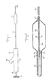
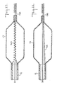
- the angioplasty balloon catheter assembly 10 one embodiment of the present invention includes a catheter tube 12, a balloon membrane 14, an adaptor or fitting 16 and a captive safety guide 18.
- the proximal end of the catheter 12 fits into and is sealed to adaptor 16.
- Adaptor 16, which has a leg 24, is preferably molded or machined of an inert, biologically compatible material.
- the safety guide or guide wire 18 Passing through the entire balloon catheter assembly is the safety guide or guide wire 18.
- the guide wire is provided with a rotatable knob 22 and at its distal end is a very flexible coil spring 20.
- proximal end 26 of balloon membrane 14 is attached and sealed to the distal end of catheter 12 in conventional fashion, for example by gluing, chemical welding or the like.
- the distal end 30 of balloon 14 is attached and sealed, again in conventional fashion, to the distal end portion of guide tube 28.
- guide tube 28 is attached to catheter tube 12, preferably by a few or a series of circumferentially spaced spot welds 32.
- guide tube 28 acts not merely as a guide for the safety guide wire, but as the support member for the balloon as well.
- at least some axial force can be transmitted directly from the catheter tube to the guide tube and thence to the distal end of the balloon.
- guide tube 28 is attached to catheter tube 12 and because balloon membrane 14 is attached to tube 28 at one end and to tube 12 at the other, expansion of the membrane tends to stress the points of attachment at both ends. Accordingly, if one wishes to avoid such stresses, a cut 29 may be made in guide tube 28 to permit axial movement of its distal end relative to its proximal end, thereby preventing the development of stress at the points of attachment. Despite this cut, however, guide tube 28 acts as a support member for the balloon. Safety guide 18 acts as a necessary support member only to bridge the gap created by cut 29. As another alternative, a spring can be employed to bridge this gap. It should be understood, however, that stress relief means such as cut 29 are not necessary to practice the instant invention.
- the guide tube need not be attached to catheter tube 12. Instead, it can float freely in the lumen of tube 12. When not so attached, there is even less need for stress relief cut 29 (Figure 8), although it still may be provided.
- the guide tube need not be made of solid wall tubing nor need it be circular in cross section. All that is required is that a seal be established to prevent blood from entering the lumen of the catheter and/or the balloon chamber.
- the guide tube can be filled with a thixotropic material.
- Another method would be to employ an elastomeric seal.
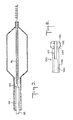
- the main body of safety guide 18 is comprised of two segments, a proximal segment 34 and a distal segment 36.
- Segment 34 is the longer of the two and has a larger diameter than that of segment 36.
- segment 34 is attached to knob 22 and at its distal end it is attached to segment 36.
- Segment 36 is attached at its proximal end to segment 34, and at its distal end it is attached to or formed into a coil 20.
- segment 36 passes through guide tube 28. Accordingly, the inside diameter of guide tube 28 must be larger than the diameter of segment 36. Obviously, the dimensions of these two cooperating elements may vary depending upon the size of the balloon being employed. However, in a typical small diameter or predilatation catheter having an expanded balloon diameter of between about .040 and about .160 inches, the guide tube might have an outside diameter of about .010 inches and an inside diameter of .007 inches, whereas the safety guide segment 36 might have a diameter of .007 inches and segment 34 might have a diameter of .013 inches.
- the balloon portion of a predilatation catheter like that just referred to is generally about one inch long, with the catheter tube 12 having an inside diameter of about .024 inches and an outside diameter of about .032 inches.
- a shoulder 38 is formed where they meet.
- the outside diameter of the shoulder is made larger than the inside diameter of guide tube 28.
- the guide tube need be only so long as to prevent its leaving the mouth of catheter 12 when balloon membrane is inflated, it may be desireable, as is seen, for example, in Figures 3 and 8, to extend it slightly further into catheter 12 in order to improve the seal that is created as a result of the close tolerances between the inside diameter of the guide tube and the outside diameter of the distal segment of the guide wire. It is believed, however, that the guide tube should not extend into catheter 12 for a substantial portion of the length of catheter 12. Most advantageously, the guide tube should not extend into catheter 12 for more than about 25% of the catheter's length, and preferably not more than about 10% of its length.
- safety guide 18 effectively plugs the lumen of guide tube 28, because of the innovative structural arrangement at the proximal end of tube 28, fluid communication is maintained between the lumen of catheter tube 12 and the balloon chamber. Moreover, such communication is maintained without employing a dual lumen catheter.
- safety guide segment 36 may be attached to or may itself be formed into a coil 20.
- the outside diameter of coil 20 can be made larger than the inside diameter of guide tube 28, in which case axial movement of safety guide 18 would be limited by shoulder face 38 in the distal direction and by coil 20 in the proximal direction.
- proximal segment 54 to distal segment 56 of safety guide 58 is by means of a frusto-conically shaped taper 55.
- This transition segment could take on a wide variety of other shapes, for example, frusto- spherical, frusto-elliptical or the like.
- a sleeve 53 may be used to prevent the taper from being jammed into the guide tube.
- Sleeve 53 would then also provide a bearing surface between the taper and the guide tube.
- both the proximal segment 54 and the distal segment 56 of safety guide 58 may be of the same diameter with a keeper or collar mounted thereon to act as the stop means.
- the distance between the shoulder formed by face 38, and coil 20 is greater than the length of guide tube 28. This is done so as to permit varying the distance by which coil 20 leads the distal end 30 of the guide tube.
- the distance between coil 20 and the shoulder can be the same as the length of guide tube 28.
- safety guide 18 would not be able to move axially relative to balloon 14, but would still be able to rotate.
- no coil were to be used or if the coil were used but it were to be small enough to fit through the guide tube, then there would be no restriction on its movement in the proximal direction.
- the diameter of the main body, or proximal segment of the safety guide will be significantly larger than that of the distal segment.
- the axial force necessary to advance the catheter assembly through the arterial tree and into the stenosis of the lesion will be transmitted in part by the catheter tube and in part by the safety guide. Since it is the proximal portion of the safety guide that will be carrying the safety guide portion of the load, the larger the diameter of that segment, the greater the force it can transmit.
- the diameter of the safety guide As small as possible.
- the diameter of its distal segment can be made significantly smaller than that of the smallest suitable indwelling safety wire.
- the safety guide can be made free to rotate and/or to move axially without interfering with the ability of the balloon to be fed into and through the arterial system or with its efficient functioning once in place.
- knob 22 is provided in order for safety guide 18 to transmit axial force from its proximal end to its distal end and thence to guide tube 28, knob 22 is provided.
- cooperating structure as best seen in Figure 5, is provided to permit the cooperative interaction referred to above. This structure permits axial movement of the safety guide relative to fitting 16 without interfering with the freedom of the safety guide to rotate within the fitting and within the catheter tube.
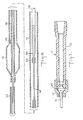
- the adaptor 16 of Figure 4 is removable from and reattachable to catheter 12.
- Adaptor 16 has a forward compression cap 62 at its distal end, which compression cap has a hollow passage 64 therethrough with an internal thread 66 in the proximal end of passage 64.
- Adaptor 16 also has a Y body midportion 68 with straight leg 70 and angled leg 72.
- Leg 70 has hollow passage 74 therethrough and leg 72 has hollow passage 76 therethrough.
- Passage 76 communicates with passage 74, and passage 74 communicates with passage 64.
- Passage 76 has an enlarged, frusto-conically shaped proximal portion 78 designed to accept, in fluid-tight engagement, fluid pressure generating means, such as a syringe (not shown).
- Leg 70 of body 68 has an external thread 80 at its distal end which is designed to engage thread 66 on compression cap 62.
- compression seal 82 Internally of cap 62 is compression seal 82. As best seen in Figure 5, seal 82 has a hollow passage 84 therethrough and sloping converging faces 86 and 88. Compression cap 62 has an internal shoulder 90 of the same slope as face 86 and Y body leg 70 terminates at its distal end in an internal taper 92 having the same slope as face 88. Passage 84 is designed to accept catheter 12 therein.
- compression seal 82 When compression cap 62 is threaded tightly onto Y body 68, compression seal 82 is squeezed between shoulder 90 and taper 92, which squeezing in turn forces the seal to expand inwardly against catheter tube 12 and produces a fluid-tight seal between fitting 16 and tube 12.
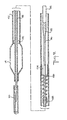
- a steel reinforcing sleeve 94 can be placed within its lumen.
- Y body leg 70 terminates in an enlarged segment 96 having an internal thread 106.
- a second compression seal 98 is placed within segment 96 between back-up plates 100 and 102. Seal 98 has a hollow passage therethrough designed to accept therein guide wire 18.
- Proximal of leg 70 is compression knob 108 having a hollow passage 110 therethrough, an enlarged segment 112 and a reduced diameter segment 114. Segment 114 is provided with an external thread 116 designed to engage internal thread 106 at the proximal end of leg 70.
- Rotation of knob 108 relative to Y body 68 compresses seal 98 between plates 102 and 100 causing it to expand inwardly against guide wire 18 thereby forming a fluid-tight seal.
- seal 98 is made of a deformable plastic and safety guide 18 is preferably stainless steel, a fluid-tight seal can be achieved without preventing rotation or axial movement of the safety guide within the seal.
- Adaptor 16 is also provided with a torque handle 118 having hollow passage 120 therethrough.
- the outside diameter of the distal segment 122 of handle 118 is sized to fit slidably within passage 110.
- Proximal of segment 122 is rotating knob 124 having a diameter greater than that of segment 122 as well as of compression knob 108.
- the distal face 126 of knob 124 acts as a stop or shoulder to limit axial travel in the distal direction of handle 118 relative to compression knob 108.
- the proximal end of handle 118 is provided with an external thread 128 designed to engage the internal thread 130 on rear compression cap 132.
- a metal split collet 134 having a sleeve portion 136, a head portion 138, a hollow passage 140 therethrough sized to accept safety guide 18 therein and a cut 142 running axially through head portion 134 and partially through sleeve portion 136.
- Sleeve portion 136 is sized to fit within the proximal end of the hollow passage 120, but head portion 138 is too large to fit within that cavity.
- Head portion 138 is provided with external converging faces 144 and 146 designed to cooperate with similarly sloping internal faces on handle 108 and on rear compression cap 132.
- safety guide 18 which extends proximally of the end of tube 12, is passed through adaptor 16, while tube 12 is fed into forward compression cap 62 and through compression seal 82.
- Cap 62 is than threaded tightly onto Y body 68 to grab tube 12 and prevent its removal.
- Compression knob 108 is then threaded tightly into the proximal end of Y body leg 70 to seal that end of leg 70 and prevent the escape of fluid therefrom.
- rear compression cap 132 is tightened onto handle 118 until guide wire 18 is held firmly therein.
- adaptor 16 has been described for use in connection with an angioplasty catheter, its utility is not nearly so limited. It can be employed with any catheter that might benefit from having a detachable/reattachable fitting.
- adaptor 16 offers the physician a degree of flexibility heretofore unheard of. For example, it permits removal of the guide wire from the catheter without removing the fitting. This can be accomplished simply by unscrewing compression knob 108 from enlarged segment 96 of leg 70 and loosening compression cap 132 so as to release the grip of collet 134. After the guide wire has been removed, compression knob 108 con be replaced by a solid cap (not shown). Screwing such a cap into enlarged segment 96 would maintain a fluid tight seal at the proximal end of the adaptor.
- adaptor 16 can be removed without disturbing either the guide wire or the catheter tube.
- FIG. 7 shows a detachable/reattachable adaptor 17 designed for use without a guide wire.
- leg 70 of Figure 4 straight leg 70 of Figure 4 and all its associated fittings and components have been eliminated.
- leg 72 which in Figure 4 was at an angle, is straight in Figure 7.
- catheter 12 is necked down at its distal end 154.
- catheter extension tube 152 the proximal end of which fits over the necked down portion 154 of catheter 12.
- the outside diameter of extension 152 should be smaller than the outside diameter of the main body of catheter 12, and a fluid tight seal should be established between the extension and the catheter.
- This seal can be established by any conventional means suitable to the materials being employed.
- catheter 12 be of thin walled stainless steel tubing and extension 152 be of modified PET.
- other biocompatible materials may also be suitable.
- guide tube 28 extends into catheter extension 152, but stops short of the distal end of catheter 12. Between the proximal end of guide tube 28 and the distal end of catheter 12, there is provided a coil spring 150. As can be seen, the necked down end of catheter 12 forms a shoulder 156 inside catheter extension 152. At its proximal end, spring 150 abuts this shoulder 156 and at its distal end spring 150 abuts the proximal end of guide tube 28.
- a cap 158 may be provided over the proximal end of guide tube 28 to facilitate the even distribution of force transmitted from spring 150 to tube 28 and to reinforce the end of tube 28.
- a radiopaque marker 142 is provided on the embodiments of Figures 8 and 9 and can be used by the physician viewing the procedure under fluoroscopy to determine where the balloon membrane begins. Similar radiopaque markers would probably be desireable on any of the embodiments of the instant invention. Practice of this invention, however, does not depend upon the use of radiopaque markers.
- the guide tube may also be possible for the guide tube to be short, as is depicted at 158 in Figures 10 and 11.
- the catheter 12 extends to the proximal end of balloon 14 similar to the structure depicted in Figures 2 and 3.
- axial force is transmitted to guide tube 158 through spring 160, whereas in Figure 11 wire 162 serves this purpose.
- a suitable artery usually the femoral artery
- the balloon catheter is then inserted into the artery and fed through the arterial tree, again, all in conventional fashion. Initially, and until an obstruction is reached, the balloon can be advanced simply by pushing on the catheter tube.
- rotating knob 22 can be used to steer the distal tip of guide wire 18 around it. Also, axial force can be applied to knob 22 to facilitate feeding of the balloon past the obstruction. Feeding of the balloon through the arterial system can continue by pushing on tube 12 and/or on fitting 16 simultaneously, thereby causing the transmission of axial forces to be shared by the catheter tube and the safety guide.
- the guide tube will begin to slide axially in the proximal direction relative to catheter 12 until it encounters shoulder 38 (in the embodiment of Figure 2) or taper 55 (of the embodiment of Figures 3 and 8).
- means could be provided anywhere along distal segment 36 to prevent or restrict axial movement of that segment relative to the guide tube.
- a retaining ring (not shown) could be affixed to segment 36 and a cooperating annular cut-out provided on the inside of guide tube 28. If the length of the annular cut-out were greater than the thickness of the retaining ring, there would be leeway for a limited amount of relative axial movement. If the two were about the same size, substantially no relative motion could occur.
- the safety guide can be made to exit the catheter tube before the latter enters the adaptor.
- a second adaptor would be provided solely for the safety guide, with the first adaptor acting merely as the interface for connecting the catheter tube to the source of fluid pressure.
Applications Claiming Priority (2)
| Application Number | Priority Date | Filing Date | Title |
|---|---|---|---|
| US07/743,189 US5318529A (en) | 1989-09-06 | 1991-08-09 | Angioplasty balloon catheter and adaptor |
| US743189 | 1991-08-09 |
Publications (3)
| Publication Number | Publication Date |
|---|---|
| EP0528294A2 true EP0528294A2 (de) | 1993-02-24 |
| EP0528294A3 EP0528294A3 (en) | 1993-05-12 |
| EP0528294B1 EP0528294B1 (de) | 1998-09-30 |
Family
ID=24987839
Family Applications (1)
| Application Number | Title | Priority Date | Filing Date |
|---|---|---|---|
| EP92113497A Expired - Lifetime EP0528294B1 (de) | 1991-08-09 | 1992-08-07 | Ballonkatheter für Angioplastik und Adapter |
Country Status (10)
| Country | Link |
|---|---|
| US (4) | US5318529A (de) |
| EP (1) | EP0528294B1 (de) |
| JP (1) | JPH05237192A (de) |
| AR (1) | AR245597A1 (de) |
| AT (1) | ATE171631T1 (de) |
| AU (1) | AU661002B2 (de) |
| BR (1) | BR9203081A (de) |
| CA (1) | CA2075386A1 (de) |
| DE (1) | DE69227163T2 (de) |
| MX (1) | MX9204603A (de) |
Cited By (7)
| Publication number | Priority date | Publication date | Assignee | Title |
|---|---|---|---|---|
| US5312340A (en) * | 1992-03-17 | 1994-05-17 | Scimed Life Systems, Inc. | Balloon dilatation catheter having dual sealing plugs |
| US5441484A (en) * | 1992-03-17 | 1995-08-15 | Scimed Life Systems, Inc. | Balloon dilatation catheter having a free core wire |
| US5484408A (en) * | 1989-04-13 | 1996-01-16 | Scimed Life Systems, Inc. | Innerless catheter |
| EP0743867A1 (de) * | 1994-03-01 | 1996-11-27 | Boston Scientific Corporation | Auf einem kerndraht abnehmbar angeordneter ballon |
| WO2009055941A1 (de) * | 2007-10-29 | 2009-05-07 | Schwager Medica | Katheter |
| CN103533983A (zh) * | 2011-03-30 | 2014-01-22 | 康奈尔大学 | 内腔访查装置及其使用方法 |
| EP3024528A4 (de) * | 2013-07-25 | 2017-07-19 | Merit Medical Systems, Inc. | Robotische kathetersysteme und verfahren |
Families Citing this family (150)
| Publication number | Priority date | Publication date | Assignee | Title |
|---|---|---|---|---|
| US6071273A (en) * | 1988-02-29 | 2000-06-06 | Scimed Life Systems, Inc. | Fixed wire dilatation balloon catheter |
| US5484409A (en) * | 1989-08-25 | 1996-01-16 | Scimed Life Systems, Inc. | Intravascular catheter and method for use thereof |
| US5976107A (en) | 1991-07-05 | 1999-11-02 | Scimed Life Systems. Inc. | Catheter having extendable guide wire lumen |
| US5417658A (en) * | 1992-03-17 | 1995-05-23 | Scimed Life Systems, Inc. | Balloon dilatation catheter having a torsionally soft component |
| US5413560A (en) * | 1992-03-30 | 1995-05-09 | Pameda N.V. | Method of rapid catheter exchange |
| JP3638304B2 (ja) * | 1994-02-25 | 2005-04-13 | シメッド ライフ システムズ インコーポレイテッド | 脈管内カテーテル |
| US5458639A (en) * | 1994-08-05 | 1995-10-17 | Medtronic, Inc. | Catheter balloon distal bond |
| US5549580A (en) * | 1995-01-23 | 1996-08-27 | Cordis Corporation | Catheter having a flexible distal tip and method of manufacturing |
| DE69629555T2 (de) | 1995-03-31 | 2004-07-01 | Medtronic AVE, Inc., Santa Rosa | Einlumiger ballonkatheter |
| NL1001564C2 (nl) * | 1995-11-02 | 1997-05-13 | Timotheus Theodorus Cornelis O | Systeem van apparaten voor het behandelen van de ureter en/of de pyelo-ureterovergang. |
| US5810869A (en) * | 1996-11-18 | 1998-09-22 | Localmed, Inc. | Methods for loading coaxial catheters |
| US6013085A (en) * | 1997-11-07 | 2000-01-11 | Howard; John | Method for treating stenosis of the carotid artery |
| US6113579A (en) | 1998-03-04 | 2000-09-05 | Scimed Life Systems, Inc. | Catheter tip designs and methods for improved stent crossing |
| US6517515B1 (en) | 1998-03-04 | 2003-02-11 | Scimed Life Systems, Inc. | Catheter having variable size guide wire lumen |
| US6156053A (en) * | 1998-05-01 | 2000-12-05 | Intella Interventional Systems, Inc. | Dual catheter assembly |
| CA2345921C (en) * | 1998-06-12 | 2005-01-25 | Cardiac Pacemakers, Inc. | Modified guidewire for left ventricular access lead |
| US6648854B1 (en) | 1999-05-14 | 2003-11-18 | Scimed Life Systems, Inc. | Single lumen balloon-tipped micro catheter with reinforced shaft |
| EP1194074A4 (de) * | 1999-05-19 | 2002-09-11 | Innerdyne Medical Inc | System und verfahren um vaskulären zugriff zu ermöglichen |
| US6471968B1 (en) | 2000-05-12 | 2002-10-29 | Regents Of The University Of Michigan | Multifunctional nanodevice platform |
| US6569180B1 (en) * | 2000-06-02 | 2003-05-27 | Avantec Vascular Corporation | Catheter having exchangeable balloon |
| US6620149B1 (en) | 2000-10-05 | 2003-09-16 | Scimed Life Systems, Inc. | Corewire securement system |
| US6533751B2 (en) | 2001-01-09 | 2003-03-18 | Andrew Cragg | Micro catheter and guidewire system having improved pushability and control |
| US6636758B2 (en) | 2001-05-01 | 2003-10-21 | Concentric Medical, Inc. | Marker wire and process for using it |
| US6638245B2 (en) | 2001-06-26 | 2003-10-28 | Concentric Medical, Inc. | Balloon catheter |
| US6702782B2 (en) | 2001-06-26 | 2004-03-09 | Concentric Medical, Inc. | Large lumen balloon catheter |
| EP1401526B1 (de) | 2001-07-05 | 2006-12-06 | Precision Vascular Systems, Inc. | Medizinische vorrichtung mit drehmoment übertragendem weichem endstück und verfahren zu seiner formgebung |
| US7052487B2 (en) * | 2001-10-26 | 2006-05-30 | Cohn William E | Method and apparatus for reducing mitral regurgitation |
| US7445629B2 (en) * | 2002-01-31 | 2008-11-04 | Boston Scientific Scimed, Inc. | Medical device for delivering biologically active material |
| US7326245B2 (en) * | 2002-01-31 | 2008-02-05 | Boston Scientific Scimed, Inc. | Medical device for delivering biologically active material |
| US7125420B2 (en) * | 2002-02-05 | 2006-10-24 | Viacor, Inc. | Method and apparatus for improving mitral valve function |
| US6866679B2 (en) | 2002-03-12 | 2005-03-15 | Ev3 Inc. | Everting stent and stent delivery system |
| US7914467B2 (en) | 2002-07-25 | 2011-03-29 | Boston Scientific Scimed, Inc. | Tubular member having tapered transition for use in a medical device |
| US8377035B2 (en) | 2003-01-17 | 2013-02-19 | Boston Scientific Scimed, Inc. | Unbalanced reinforcement members for medical device |
| US20060136053A1 (en) * | 2003-05-27 | 2006-06-22 | Rourke Jonathan M | Method and apparatus for improving mitral valve function |
| US6994718B2 (en) * | 2003-10-29 | 2006-02-07 | Medtronic Vascular, Inc. | Distal protection device for filtering and occlusion |
| US7716801B2 (en) * | 2003-11-24 | 2010-05-18 | Medtronic Vascular, Inc. | Low-profile distal protection device |
| US7824345B2 (en) | 2003-12-22 | 2010-11-02 | Boston Scientific Scimed, Inc. | Medical device with push force limiter |
| US7887529B2 (en) * | 2004-04-19 | 2011-02-15 | Boston Scientific Scimed, Inc. | Hybrid micro guide catheter |
| US9480589B2 (en) * | 2005-05-13 | 2016-11-01 | Boston Scientific Scimed, Inc. | Endoprosthesis delivery system |
| US7780723B2 (en) | 2005-06-13 | 2010-08-24 | Edwards Lifesciences Corporation | Heart valve delivery system |
| US20070043389A1 (en) * | 2005-08-05 | 2007-02-22 | Shintech, Llc | System for treating chronic total occlusion caused by lower extremity arterial disease |
| US7850623B2 (en) | 2005-10-27 | 2010-12-14 | Boston Scientific Scimed, Inc. | Elongate medical device with continuous reinforcement member |
| US20090118825A1 (en) * | 2005-11-23 | 2009-05-07 | Jonathan Rourke | Method and apparatus for improving mitral valve function |
| IL175477A (en) * | 2006-05-08 | 2013-09-30 | Efraim Kfir | A kit for lifting the sinus membranes for use in dental implant surgery |
| US20060282110A1 (en) * | 2006-07-11 | 2006-12-14 | Conor Medsystems, Inc. | Advanceable, non-removable guide wire balloon catheter delivery system for a stent and method |
| US20080015675A1 (en) * | 2006-07-11 | 2008-01-17 | Conor Medsystems, Inc. | Balloon catheter system and method |
| US8551020B2 (en) | 2006-09-13 | 2013-10-08 | Boston Scientific Scimed, Inc. | Crossing guidewire |
| US9050438B2 (en) | 2006-10-21 | 2015-06-09 | Vesatek, Llc | Guidewire manipulation device |
| WO2008097993A2 (en) | 2007-02-05 | 2008-08-14 | Boston Scientific Limited | Thrombectomy apparatus and method |
| US7896840B2 (en) * | 2007-04-05 | 2011-03-01 | Boston Scientific Scimed, Inc. | Catheter having internal mechanisms to encourage balloon re-folding |
| EP2173427B1 (de) * | 2007-07-09 | 2011-11-30 | Cook Medical Technologies LLC | Faltkontrollmechanismus für einen Ballon |
| EP2170452B1 (de) * | 2007-07-09 | 2013-02-13 | Cook Medical Technologies LLC | Ballonkatheter mit deflationsmechanismus |
| US8858490B2 (en) | 2007-07-18 | 2014-10-14 | Silk Road Medical, Inc. | Systems and methods for treating a carotid artery |
| US8409114B2 (en) | 2007-08-02 | 2013-04-02 | Boston Scientific Scimed, Inc. | Composite elongate medical device including distal tubular member |
| US8105246B2 (en) | 2007-08-03 | 2012-01-31 | Boston Scientific Scimed, Inc. | Elongate medical device having enhanced torque and methods thereof |
| US8821477B2 (en) | 2007-08-06 | 2014-09-02 | Boston Scientific Scimed, Inc. | Alternative micromachined structures |
| US9808595B2 (en) | 2007-08-07 | 2017-11-07 | Boston Scientific Scimed, Inc | Microfabricated catheter with improved bonding structure |
| US8066731B2 (en) * | 2007-08-20 | 2011-11-29 | Olympus Medical Systems Corp. | Treatment device |
| US7841994B2 (en) | 2007-11-02 | 2010-11-30 | Boston Scientific Scimed, Inc. | Medical device for crossing an occlusion in a vessel |
| US10166127B2 (en) | 2007-12-12 | 2019-01-01 | Intact Vascular, Inc. | Endoluminal device and method |
| US9603730B2 (en) | 2007-12-12 | 2017-03-28 | Intact Vascular, Inc. | Endoluminal device and method |
| US8128677B2 (en) * | 2007-12-12 | 2012-03-06 | Intact Vascular LLC | Device and method for tacking plaque to a blood vessel wall |
| US7896911B2 (en) | 2007-12-12 | 2011-03-01 | Innovasc Llc | Device and method for tacking plaque to blood vessel wall |
| US9375327B2 (en) | 2007-12-12 | 2016-06-28 | Intact Vascular, Inc. | Endovascular implant |
| US10022250B2 (en) | 2007-12-12 | 2018-07-17 | Intact Vascular, Inc. | Deployment device for placement of multiple intraluminal surgical staples |
| US8252834B2 (en) | 2008-03-12 | 2012-08-28 | The Regents Of The University Of Michigan | Dendrimer conjugates |
| US8376961B2 (en) | 2008-04-07 | 2013-02-19 | Boston Scientific Scimed, Inc. | Micromachined composite guidewire structure with anisotropic bending properties |
| US9061119B2 (en) | 2008-05-09 | 2015-06-23 | Edwards Lifesciences Corporation | Low profile delivery system for transcatheter heart valve |
| US8574245B2 (en) | 2008-08-13 | 2013-11-05 | Silk Road Medical, Inc. | Suture delivery device |
| US8652202B2 (en) | 2008-08-22 | 2014-02-18 | Edwards Lifesciences Corporation | Prosthetic heart valve and delivery apparatus |
| US8535243B2 (en) | 2008-09-10 | 2013-09-17 | Boston Scientific Scimed, Inc. | Medical devices and tapered tubular members for use in medical devices |
| WO2010039861A2 (en) | 2008-09-30 | 2010-04-08 | The Regents Of The University Of Michigan | Dendrimer conjugates |
| WO2010054321A2 (en) | 2008-11-07 | 2010-05-14 | The Regents Of The University Of Michigan | Methods of treating autoimmune disorders and/or inflammatory disorders |
| US8795254B2 (en) | 2008-12-10 | 2014-08-05 | Boston Scientific Scimed, Inc. | Medical devices with a slotted tubular member having improved stress distribution |
| US8926529B2 (en) | 2009-02-10 | 2015-01-06 | Vesatek, Llc | Method and apparatus for manipulating a surgical guidewire |
| WO2010111446A2 (en) * | 2009-03-25 | 2010-09-30 | Svelte Medical Systems, Inc. | Balloon delivery apparatus and method for using and manufacturing the same |
| JP4550161B1 (ja) * | 2009-04-07 | 2010-09-22 | 株式会社ユニシス | ロック機構付複合針 |
| EP2488172A4 (de) | 2009-10-13 | 2014-08-13 | Univ Michigan | Dendrimerzusammensetzung und verfahren zu ihrer synthese |
| WO2011059586A2 (en) | 2009-10-30 | 2011-05-19 | The Regents Of The University Of Michigan | Multifunctional small molecules |
| US8137293B2 (en) | 2009-11-17 | 2012-03-20 | Boston Scientific Scimed, Inc. | Guidewires including a porous nickel-titanium alloy |
| EP2552530A1 (de) | 2010-03-31 | 2013-02-06 | Boston Scientific Scimed, Inc. | Führungsdraht mit einem biegefestigkeitsprofil |
| US8292150B2 (en) | 2010-11-02 | 2012-10-23 | Tyco Healthcare Group Lp | Adapter for powered surgical devices |
| US8469989B2 (en) | 2010-12-15 | 2013-06-25 | Cook Medical Technologies Llc | Pushable coaxial balloon catheter |
| US8795202B2 (en) | 2011-02-04 | 2014-08-05 | Boston Scientific Scimed, Inc. | Guidewires and methods for making and using the same |
| US9155619B2 (en) | 2011-02-25 | 2015-10-13 | Edwards Lifesciences Corporation | Prosthetic heart valve delivery apparatus |
| US9072874B2 (en) | 2011-05-13 | 2015-07-07 | Boston Scientific Scimed, Inc. | Medical devices with a heat transfer region and a heat sink region and methods for manufacturing medical devices |
| US10285831B2 (en) | 2011-06-03 | 2019-05-14 | Intact Vascular, Inc. | Endovascular implant |
| US9119716B2 (en) | 2011-07-27 | 2015-09-01 | Edwards Lifesciences Corporation | Delivery systems for prosthetic heart valve |
| WO2013085718A1 (en) | 2011-12-08 | 2013-06-13 | The Regents Of The University Of Michigan | Multifunctional small molecules |
| EP3733134A1 (de) | 2012-01-25 | 2020-11-04 | Intact Vascular, Inc. | Endoluminale vorrichtung |
| AU2015202690B2 (en) * | 2012-02-23 | 2016-09-22 | Covidien Lp | Methods and apparatus for luminal stenting |
| US20130226278A1 (en) | 2012-02-23 | 2013-08-29 | Tyco Healthcare Group Lp | Methods and apparatus for luminal stenting |
| US9072624B2 (en) | 2012-02-23 | 2015-07-07 | Covidien Lp | Luminal stenting |
| AU2016277624B2 (en) * | 2012-02-23 | 2018-11-15 | Covidien Lp | A stent delivery system |
| US9078659B2 (en) | 2012-04-23 | 2015-07-14 | Covidien Lp | Delivery system with hooks for resheathability |
| US9233015B2 (en) | 2012-06-15 | 2016-01-12 | Trivascular, Inc. | Endovascular delivery system with an improved radiopaque marker scheme |
| US9724222B2 (en) | 2012-07-20 | 2017-08-08 | Covidien Lp | Resheathable stent delivery system |
| US10159479B2 (en) * | 2012-08-09 | 2018-12-25 | Silk Road Medical, Inc. | Suture delivery device |
| US10130500B2 (en) | 2013-07-25 | 2018-11-20 | Covidien Lp | Methods and apparatus for luminal stenting |
| US10265207B2 (en) | 2013-08-27 | 2019-04-23 | Covidien Lp | Delivery of medical devices |
| US9782186B2 (en) | 2013-08-27 | 2017-10-10 | Covidien Lp | Vascular intervention system |
| US9901716B2 (en) * | 2013-09-10 | 2018-02-27 | Cook Medical Technologies Llc | Tipless balloon catheter with stiffening member through balloon |
| ES2580334T3 (es) | 2014-01-13 | 2016-08-23 | Yang, Guanghua | Composiciones de dendrímeros, métodos de síntesis, y sus usos |
| US9433520B2 (en) | 2015-01-29 | 2016-09-06 | Intact Vascular, Inc. | Delivery device and method of delivery |
| US9375336B1 (en) | 2015-01-29 | 2016-06-28 | Intact Vascular, Inc. | Delivery device and method of delivery |
| CA2979712C (en) | 2015-03-25 | 2024-01-23 | The Regents Of The University Of Michigan | Nanoparticle compositions for delivery of biomacromolecules |
| US9907610B2 (en) | 2015-05-07 | 2018-03-06 | Biosense Webster (Israel) Ltd. | Spring-loaded balloon |
| JP6885923B2 (ja) | 2015-08-12 | 2021-06-16 | ヴェサテック エルエルシー | 長尺の医療機器を操作するためのシステムおよび方法 |
| US10179046B2 (en) | 2015-08-14 | 2019-01-15 | Edwards Lifesciences Corporation | Gripping and pushing device for medical instrument |
| US10561440B2 (en) | 2015-09-03 | 2020-02-18 | Vesatek, Llc | Systems and methods for manipulating medical devices |
| US11259920B2 (en) | 2015-11-03 | 2022-03-01 | Edwards Lifesciences Corporation | Adapter for prosthesis delivery device and methods of use |
| US10321996B2 (en) | 2015-11-11 | 2019-06-18 | Edwards Lifesciences Corporation | Prosthetic valve delivery apparatus having clutch mechanism |
| US10226263B2 (en) | 2015-12-23 | 2019-03-12 | Incuvate, Llc | Aspiration monitoring system and method |
| US10993824B2 (en) | 2016-01-01 | 2021-05-04 | Intact Vascular, Inc. | Delivery device and method of delivery |
| WO2017158436A1 (en) | 2016-03-17 | 2017-09-21 | Oslo Universitetssykehus Hf | Fusion proteins targeting tumour associated macrophages for treating cancer |
| US11219746B2 (en) | 2016-03-21 | 2022-01-11 | Edwards Lifesciences Corporation | Multi-direction steerable handles for steering catheters |
| US10799676B2 (en) | 2016-03-21 | 2020-10-13 | Edwards Lifesciences Corporation | Multi-direction steerable handles for steering catheters |
| US10799677B2 (en) | 2016-03-21 | 2020-10-13 | Edwards Lifesciences Corporation | Multi-direction steerable handles for steering catheters |
| KR20190064608A (ko) | 2016-09-29 | 2019-06-10 | 라피드 메디칼 리미티드 | 작동가능한 작동 단부를 갖는 회전 토크 전달가능한 혈관내 장치 |
| US11389172B2 (en) | 2016-09-29 | 2022-07-19 | Rapid Medical Ltd. | Rotationally torquable endovascular device with variable flexibility tip |
| WO2018104473A1 (en) | 2016-12-07 | 2018-06-14 | Oslo Universitetssykehus Hf | Compositions and methods for cell therapy |
| US10376396B2 (en) | 2017-01-19 | 2019-08-13 | Covidien Lp | Coupling units for medical device delivery systems |
| LT3682854T (lt) | 2017-04-18 | 2022-03-10 | Edwards Lifesciences Corporation | Širdies vožtuvo sandarinimo įrenginiai ir jų perdavimo įtaisai |
| US11224511B2 (en) | 2017-04-18 | 2022-01-18 | Edwards Lifesciences Corporation | Heart valve sealing devices and delivery devices therefor |
| US10973634B2 (en) | 2017-04-26 | 2021-04-13 | Edwards Lifesciences Corporation | Delivery apparatus for a prosthetic heart valve |
| US10433852B2 (en) | 2017-05-08 | 2019-10-08 | William Z. H'Doubler | Aortic occlusion balloon apparatus, system and method of making |
| US10959846B2 (en) | 2017-05-10 | 2021-03-30 | Edwards Lifesciences Corporation | Mitral valve spacer device |
| US10569058B2 (en) * | 2017-05-12 | 2020-02-25 | Ep Dynamics, Inc. | Introducer sheaths |
| JP7277389B2 (ja) | 2017-06-30 | 2023-05-18 | エドワーズ ライフサイエンシーズ コーポレイション | 経カテーテル的な弁のためのドッキングステーション |
| SG11201913126YA (en) | 2017-06-30 | 2020-01-30 | Edwards Lifesciences Corp | Lock and release mechanisms for trans-catheter implantable devices |
| US10857334B2 (en) | 2017-07-12 | 2020-12-08 | Edwards Lifesciences Corporation | Reduced operation force inflator |
| US11660218B2 (en) | 2017-07-26 | 2023-05-30 | Intact Vascular, Inc. | Delivery device and method of delivery |
| US10806573B2 (en) | 2017-08-22 | 2020-10-20 | Edwards Lifesciences Corporation | Gear drive mechanism for heart valve delivery apparatus |
| US11051939B2 (en) | 2017-08-31 | 2021-07-06 | Edwards Lifesciences Corporation | Active introducer sheath system |
| IL305364A (en) | 2017-10-18 | 2023-10-01 | Edwards Lifesciences Corp | In Hebrew: catheter assembly |
| US11207499B2 (en) | 2017-10-20 | 2021-12-28 | Edwards Lifesciences Corporation | Steerable catheter |
| WO2019173313A1 (en) | 2018-03-06 | 2019-09-12 | Medtronic Vascular, Inc. | Rapid exchange balloon catheter |
| WO2019195641A2 (en) | 2018-04-06 | 2019-10-10 | The Regents Of The University Of Michigan | Inhibitors of rho/mrtf/srf-mediated gene transcription and methods for use of the same |
| US11123209B2 (en) | 2018-04-12 | 2021-09-21 | Covidien Lp | Medical device delivery |
| US10786377B2 (en) | 2018-04-12 | 2020-09-29 | Covidien Lp | Medical device delivery |
| US11413176B2 (en) | 2018-04-12 | 2022-08-16 | Covidien Lp | Medical device delivery |
| US11071637B2 (en) | 2018-04-12 | 2021-07-27 | Covidien Lp | Medical device delivery |
| US11844914B2 (en) | 2018-06-05 | 2023-12-19 | Edwards Lifesciences Corporation | Removable volume indicator for syringe |
| US11678905B2 (en) | 2018-07-19 | 2023-06-20 | Walk Vascular, Llc | Systems and methods for removal of blood and thrombotic material |
| US11779728B2 (en) | 2018-11-01 | 2023-10-10 | Edwards Lifesciences Corporation | Introducer sheath with expandable introducer |
| US11413174B2 (en) | 2019-06-26 | 2022-08-16 | Covidien Lp | Core assembly for medical device delivery systems |
| US11154692B2 (en) | 2019-10-30 | 2021-10-26 | Rapid Medical Ltd. | Intraluminal device with looped core wire |
| AU2021330813A1 (en) | 2020-08-24 | 2023-03-02 | Edwards Lifesciences Corporation | Methods and systems for aligning a commissure of a prosthetic heart valve with a commissure of a native valve |
| CA3193292A1 (en) | 2020-08-31 | 2022-03-03 | Edwards Lifesciences Corporation | Systems and methods for crimping and device preparation |
| US11944558B2 (en) | 2021-08-05 | 2024-04-02 | Covidien Lp | Medical device delivery devices, systems, and methods |
Citations (3)
| Publication number | Priority date | Publication date | Assignee | Title |
|---|---|---|---|---|
| EP0213752A1 (de) * | 1985-07-30 | 1987-03-11 | Advanced Cardiovascular Systems, Inc. | Steuerbarer Ballondilatationskatheter mit Farbstoffinjektions- und Druckmessungsanordnungen |
| EP0368523A2 (de) * | 1988-11-10 | 1990-05-16 | C.R. Bard, Inc. | Ballondilatationskatheter mit integriertem Führungsdraht |
| WO1992008511A1 (en) * | 1990-11-19 | 1992-05-29 | Danforth Biomedical Incorporated | Highly steerable dilatation balloon catheter system |
Family Cites Families (28)
| Publication number | Priority date | Publication date | Assignee | Title |
|---|---|---|---|---|
| US4606347A (en) * | 1983-03-25 | 1986-08-19 | Thomas J. Fogarty | Inverted balloon catheter having sealed through lumen |
| US4755371A (en) * | 1983-08-08 | 1988-07-05 | Columbian Chemicals Company | Method for producing carbon black |
| US4684363A (en) * | 1984-10-31 | 1987-08-04 | American Hospital Supply Corporation | Rapidly inflatable balloon catheter and method |
| US4616653A (en) * | 1985-07-30 | 1986-10-14 | Advanced Cardiovascular Systems, Inc. | Balloon dilatation catheter with advanceable non-removable guide wire |
| CH667207A5 (fr) * | 1985-11-21 | 1988-09-30 | Sarcem Sa | Catheter a commande a distance a micro-ballonet. |
| US4775371A (en) * | 1986-09-02 | 1988-10-04 | Advanced Cardiovascular Systems, Inc. | Stiffened dilatation catheter and method of manufacture |
| US4793350A (en) * | 1987-01-06 | 1988-12-27 | Advanced Cardiovascular Systems, Inc. | Liquid filled low profile dilatation catheter |
| US4976720A (en) * | 1987-01-06 | 1990-12-11 | Advanced Cardiovascular Systems, Inc. | Vascular catheters |
| US4964409A (en) * | 1989-05-11 | 1990-10-23 | Advanced Cardiovascular Systems, Inc. | Flexible hollow guiding member with means for fluid communication therethrough |
| US4906241A (en) * | 1987-11-30 | 1990-03-06 | Boston Scientific Corporation | Dilation balloon |
| US4998917A (en) * | 1988-05-26 | 1991-03-12 | Advanced Cardiovascular Systems, Inc. | High torque steerable dilatation catheter |
| US4877031A (en) * | 1988-07-22 | 1989-10-31 | Advanced Cardiovascular Systems, Inc. | Steerable perfusion dilatation catheter |
| JP2812391B2 (ja) * | 1988-09-29 | 1998-10-22 | キヤノン株式会社 | パターン処理方法 |
| US5085636A (en) * | 1989-01-13 | 1992-02-04 | Scimed Life Systems, Inc. | Balloon catheter with inflation-deflation valve |
| US5032113A (en) * | 1989-04-13 | 1991-07-16 | Scimed Life Systems, Inc. | Innerless catheter |
| US5035686A (en) * | 1989-01-27 | 1991-07-30 | C. R. Bard, Inc. | Catheter exchange system with detachable luer fitting |
| US5002559A (en) * | 1989-11-30 | 1991-03-26 | Numed | PTCA catheter |
| WO1991009640A1 (en) * | 1989-12-28 | 1991-07-11 | Scimed Life Systems, Inc. | Dilatation balloon catheter and method of manufacture |
| WO1991013649A1 (en) * | 1990-03-16 | 1991-09-19 | Medtronic, Inc. | Dilatation catheter |
| CA2050278A1 (en) * | 1990-03-16 | 1991-09-17 | Leo Roucher | Dilatation catheter |
| US5176637A (en) * | 1990-04-19 | 1993-01-05 | Terumo Kabushiki Kaisha | Catheter equipped with a dilation element |
| AU7844091A (en) * | 1990-06-18 | 1992-01-02 | C.R. Bard Inc. | Fixed wire dilatation catheter with distal twistable segment |
| US5195989A (en) * | 1990-09-17 | 1993-03-23 | Scimed Life Systems, Inc. | Low profile catheter for increasing lumen size of a blood vessel and guide wire therefor |
| US5171221A (en) * | 1991-02-05 | 1992-12-15 | Target Therapeutics | Single lumen low profile valved balloon catheter |
| CA2068483A1 (en) * | 1991-05-15 | 1992-11-16 | Motasim Mahmoud Sirhan | Low profile dilatation catheter |
| US5217434A (en) * | 1991-10-15 | 1993-06-08 | Scimed Life Systems, Inc. | Innerless dilatation catheter with balloon stretch valve |
| US5324259A (en) * | 1991-12-18 | 1994-06-28 | Advanced Cardiovascular Systems, Inc. | Intravascular catheter with means to seal guidewire port |
| WO1993018816A1 (en) * | 1992-03-17 | 1993-09-30 | Scimed Life Systems, Inc. | Balloon dilatation catheter having a free core wire |
-
1991
- 1991-08-09 US US07/743,189 patent/US5318529A/en not_active Expired - Lifetime
-
1992
- 1992-07-29 AU AU20631/92A patent/AU661002B2/en not_active Ceased
- 1992-08-06 JP JP4210235A patent/JPH05237192A/ja not_active Withdrawn
- 1992-08-06 CA CA002075386A patent/CA2075386A1/en not_active Abandoned
- 1992-08-07 DE DE69227163T patent/DE69227163T2/de not_active Expired - Lifetime
- 1992-08-07 AT AT92113497T patent/ATE171631T1/de not_active IP Right Cessation
- 1992-08-07 BR BR929203081A patent/BR9203081A/pt not_active Application Discontinuation
- 1992-08-07 AR AR92322925A patent/AR245597A1/es active
- 1992-08-07 MX MX9204603A patent/MX9204603A/es unknown
- 1992-08-07 EP EP92113497A patent/EP0528294B1/de not_active Expired - Lifetime
-
1994
- 1994-04-19 US US08/229,696 patent/US5501668A/en not_active Expired - Fee Related
-
1996
- 1996-03-15 US US08/616,618 patent/US5800391A/en not_active Expired - Lifetime
-
1998
- 1998-09-01 US US09/144,707 patent/US6033381A/en not_active Expired - Fee Related
Patent Citations (3)
| Publication number | Priority date | Publication date | Assignee | Title |
|---|---|---|---|---|
| EP0213752A1 (de) * | 1985-07-30 | 1987-03-11 | Advanced Cardiovascular Systems, Inc. | Steuerbarer Ballondilatationskatheter mit Farbstoffinjektions- und Druckmessungsanordnungen |
| EP0368523A2 (de) * | 1988-11-10 | 1990-05-16 | C.R. Bard, Inc. | Ballondilatationskatheter mit integriertem Führungsdraht |
| WO1992008511A1 (en) * | 1990-11-19 | 1992-05-29 | Danforth Biomedical Incorporated | Highly steerable dilatation balloon catheter system |
Cited By (16)
| Publication number | Priority date | Publication date | Assignee | Title |
|---|---|---|---|---|
| US5484408A (en) * | 1989-04-13 | 1996-01-16 | Scimed Life Systems, Inc. | Innerless catheter |
| US5569201A (en) * | 1989-04-13 | 1996-10-29 | Scimed Life Systems, Inc. | Balloon catheter with distal seal |
| US6090126A (en) * | 1989-04-13 | 2000-07-18 | Scimed Life Systems, Inc. | Catheter seal |
| US5312340A (en) * | 1992-03-17 | 1994-05-17 | Scimed Life Systems, Inc. | Balloon dilatation catheter having dual sealing plugs |
| US5441484A (en) * | 1992-03-17 | 1995-08-15 | Scimed Life Systems, Inc. | Balloon dilatation catheter having a free core wire |
| EP0743867A1 (de) * | 1994-03-01 | 1996-11-27 | Boston Scientific Corporation | Auf einem kerndraht abnehmbar angeordneter ballon |
| EP0743867A4 (de) * | 1994-03-01 | 1997-10-01 | Boston Scient Corp | Auf einem kerndraht abnehmbar angeordneter ballon |
| WO2009055941A1 (de) * | 2007-10-29 | 2009-05-07 | Schwager Medica | Katheter |
| CN103533983A (zh) * | 2011-03-30 | 2014-01-22 | 康奈尔大学 | 内腔访查装置及其使用方法 |
| EP2691141A2 (de) * | 2011-03-30 | 2014-02-05 | Cornell University | Vorrichtung für intraluminalen zugang und verwendungsverfahren dafür |
| EP2691141A4 (de) * | 2011-03-30 | 2014-08-27 | Univ Cornell | Vorrichtung für intraluminalen zugang und verwendungsverfahren dafür |
| EP3024528A4 (de) * | 2013-07-25 | 2017-07-19 | Merit Medical Systems, Inc. | Robotische kathetersysteme und verfahren |
| US10086173B2 (en) | 2013-07-25 | 2018-10-02 | Merit Medical Systems, Inc. | Balloon catheter systems and methods |
| US10130797B2 (en) | 2013-07-25 | 2018-11-20 | Merit Medical Systems, Inc. | Balloon catheter systems and methods |
| AU2014292965B2 (en) * | 2013-07-25 | 2019-02-21 | Merit Medical Systems, Inc. | Balloon catheter systems and methods |
| US11219749B2 (en) | 2013-07-25 | 2022-01-11 | Merit Medical Systems, Inc. | Balloon catheter systems and methods |
Also Published As
| Publication number | Publication date |
|---|---|
| ATE171631T1 (de) | 1998-10-15 |
| BR9203081A (pt) | 1993-03-30 |
| AR245597A1 (es) | 1994-02-28 |
| DE69227163D1 (de) | 1998-11-05 |
| AU2063192A (en) | 1993-02-11 |
| JPH05237192A (ja) | 1993-09-17 |
| US6033381A (en) | 2000-03-07 |
| EP0528294A3 (en) | 1993-05-12 |
| CA2075386A1 (en) | 1993-02-10 |
| US5501668A (en) | 1996-03-26 |
| US5800391A (en) | 1998-09-01 |
| EP0528294B1 (de) | 1998-09-30 |
| DE69227163T2 (de) | 1999-05-20 |
| AU661002B2 (en) | 1995-07-13 |
| MX9204603A (es) | 1993-02-01 |
| US5318529A (en) | 1994-06-07 |
Similar Documents
| Publication | Publication Date | Title |
|---|---|---|
| US5318529A (en) | Angioplasty balloon catheter and adaptor | |
| EP0994742B1 (de) | Angioplastischer führungsdraht mit wechselnder steifheit | |
| US5439445A (en) | Support catheter assembly | |
| US4976690A (en) | Variable stiffness angioplasty catheter | |
| US5730734A (en) | Catheter systems with interchangeable parts | |
| US5045061A (en) | Balloon catheter and locking guidewire system | |
| EP0629417B1 (de) | Doppellumiger, einen geringen Querschnitt aufweisender Ballonperfusionskatheter mit einer Axial verschubbaren inneren Führungshülse | |
| US5383890A (en) | Low-profile single-lumen perfusion balloon catheter | |
| JP2933389B2 (ja) | 遠位端側にガイドワイヤ用の管腔を有するバルーンカテーテル | |
| CA2322299C (en) | Convertible catheter incorporating a collapsible lumen | |
| EP0231601B1 (de) | Kathetersatz zur angioplastischen Anwendung | |
| US6113557A (en) | Variable stiffness angioplasty guide wire | |
| US5334147A (en) | Rapid exchange type dilatation catheter | |
| US5759191A (en) | Coaxial PTCA catheter with anchor joint | |
| EP0418677A1 (de) | Steuerbarer Gefässkatheter für die Durchgängigkeit eines Blutgefässes | |
| US20030125751A1 (en) | Catheter | |
| US5246009A (en) | Guide wire assembly and method for catheter exchange | |
| WO2003037419A2 (en) | Catheter having an improved distal tip | |
| JP2960114B2 (ja) | カテーテル | |
| US20040092867A1 (en) | Catheter with full-length core wire shaft for core wire interchangeability | |
| US5341817A (en) | Elongated guidewire for use in dilation procedures | |
| US20040092868A1 (en) | Catheter with full-length core wire shaft for core wire interchangeability | |
| IE20020529A1 (en) | A Catheter |
Legal Events
| Date | Code | Title | Description |
|---|---|---|---|
| PUAI | Public reference made under article 153(3) epc to a published international application that has entered the european phase |
Free format text: ORIGINAL CODE: 0009012 |
|
| AK | Designated contracting states |
Kind code of ref document: A2 Designated state(s): AT BE CH DE DK ES FR GB GR IE IT LI LU MC NL PT SE |
|
| PUAL | Search report despatched |
Free format text: ORIGINAL CODE: 0009013 |
|
| AK | Designated contracting states |
Kind code of ref document: A3 Designated state(s): AT BE CH DE DK ES FR GB GR IE IT LI LU MC NL PT SE |
|
| 17P | Request for examination filed |
Effective date: 19931109 |
|
| RAP1 | Party data changed (applicant data changed or rights of an application transferred) |
Owner name: BOSTON SCIENTIFIC CORPORATION |
|
| 17Q | First examination report despatched |
Effective date: 19950705 |
|
| RAP1 | Party data changed (applicant data changed or rights of an application transferred) |
Owner name: BOSTON SCIENTIFIC CORPORATION |
|
| RAP3 | Party data changed (applicant data changed or rights of an application transferred) |
Owner name: BOSTON SCIENTIFIC CORPORATION |
|
| GRAG | Despatch of communication of intention to grant |
Free format text: ORIGINAL CODE: EPIDOS AGRA |
|
| GRAG | Despatch of communication of intention to grant |
Free format text: ORIGINAL CODE: EPIDOS AGRA |
|
| GRAG | Despatch of communication of intention to grant |
Free format text: ORIGINAL CODE: EPIDOS AGRA |
|
| GRAH | Despatch of communication of intention to grant a patent |
Free format text: ORIGINAL CODE: EPIDOS IGRA |
|
| GRAH | Despatch of communication of intention to grant a patent |
Free format text: ORIGINAL CODE: EPIDOS IGRA |
|
| GRAA | (expected) grant |
Free format text: ORIGINAL CODE: 0009210 |
|
| AK | Designated contracting states |
Kind code of ref document: B1 Designated state(s): AT BE CH DE DK ES FR GB GR IE IT LI LU MC NL PT SE |
|
| PG25 | Lapsed in a contracting state [announced via postgrant information from national office to epo] |
Ref country code: ES Free format text: THE PATENT HAS BEEN ANNULLED BY A DECISION OF A NATIONAL AUTHORITY Effective date: 19980930 Ref country code: BE Free format text: LAPSE BECAUSE OF FAILURE TO SUBMIT A TRANSLATION OF THE DESCRIPTION OR TO PAY THE FEE WITHIN THE PRESCRIBED TIME-LIMIT Effective date: 19980930 Ref country code: AT Free format text: LAPSE BECAUSE OF FAILURE TO SUBMIT A TRANSLATION OF THE DESCRIPTION OR TO PAY THE FEE WITHIN THE PRESCRIBED TIME-LIMIT Effective date: 19980930 Ref country code: LI Free format text: LAPSE BECAUSE OF FAILURE TO SUBMIT A TRANSLATION OF THE DESCRIPTION OR TO PAY THE FEE WITHIN THE PRESCRIBED TIME-LIMIT Effective date: 19980930 Ref country code: NL Free format text: LAPSE BECAUSE OF FAILURE TO SUBMIT A TRANSLATION OF THE DESCRIPTION OR TO PAY THE FEE WITHIN THE PRESCRIBED TIME-LIMIT Effective date: 19980930 Ref country code: GR Free format text: LAPSE BECAUSE OF NON-PAYMENT OF DUE FEES Effective date: 19980930 Ref country code: CH Free format text: LAPSE BECAUSE OF FAILURE TO SUBMIT A TRANSLATION OF THE DESCRIPTION OR TO PAY THE FEE WITHIN THE PRESCRIBED TIME-LIMIT Effective date: 19980930 |
|
| REF | Corresponds to: |
Ref document number: 171631 Country of ref document: AT Date of ref document: 19981015 Kind code of ref document: T |
|
| REG | Reference to a national code |
Ref country code: CH Ref legal event code: EP |
|
| REF | Corresponds to: |
Ref document number: 69227163 Country of ref document: DE Date of ref document: 19981105 |
|
| ET | Fr: translation filed | ||
| REG | Reference to a national code |
Ref country code: IE Ref legal event code: FG4D |
|
| PG25 | Lapsed in a contracting state [announced via postgrant information from national office to epo] |
Ref country code: PT Free format text: LAPSE BECAUSE OF FAILURE TO SUBMIT A TRANSLATION OF THE DESCRIPTION OR TO PAY THE FEE WITHIN THE PRESCRIBED TIME-LIMIT Effective date: 19981230 |
|
| PG25 | Lapsed in a contracting state [announced via postgrant information from national office to epo] |
Ref country code: SE Free format text: LAPSE BECAUSE OF FAILURE TO SUBMIT A TRANSLATION OF THE DESCRIPTION OR TO PAY THE FEE WITHIN THE PRESCRIBED TIME-LIMIT Effective date: 19981231 Ref country code: DK Free format text: LAPSE BECAUSE OF FAILURE TO SUBMIT A TRANSLATION OF THE DESCRIPTION OR TO PAY THE FEE WITHIN THE PRESCRIBED TIME-LIMIT Effective date: 19981231 |
|
| NLV1 | Nl: lapsed or annulled due to failure to fulfill the requirements of art. 29p and 29m of the patents act | ||
| REG | Reference to a national code |
Ref country code: CH Ref legal event code: PL |
|
| PGFP | Annual fee paid to national office [announced via postgrant information from national office to epo] |
Ref country code: GB Payment date: 19990721 Year of fee payment: 8 |
|
| PLBE | No opposition filed within time limit |
Free format text: ORIGINAL CODE: 0009261 |
|
| STAA | Information on the status of an ep patent application or granted ep patent |
Free format text: STATUS: NO OPPOSITION FILED WITHIN TIME LIMIT |
|
| PG25 | Lapsed in a contracting state [announced via postgrant information from national office to epo] |
Ref country code: LU Free format text: LAPSE BECAUSE OF NON-PAYMENT OF DUE FEES Effective date: 19990807 Ref country code: IE Free format text: LAPSE BECAUSE OF NON-PAYMENT OF DUE FEES Effective date: 19990807 |
|
| 26N | No opposition filed | ||
| PG25 | Lapsed in a contracting state [announced via postgrant information from national office to epo] |
Ref country code: MC Free format text: LAPSE BECAUSE OF NON-PAYMENT OF DUE FEES Effective date: 20000229 |
|
| PG25 | Lapsed in a contracting state [announced via postgrant information from national office to epo] |
Ref country code: GB Free format text: LAPSE BECAUSE OF NON-PAYMENT OF DUE FEES Effective date: 20000807 |
|
| REG | Reference to a national code |
Ref country code: IE Ref legal event code: MM4A |
|
| GBPC | Gb: european patent ceased through non-payment of renewal fee |
Effective date: 20000807 |
|
| PG25 | Lapsed in a contracting state [announced via postgrant information from national office to epo] |
Ref country code: IT Free format text: LAPSE BECAUSE OF NON-PAYMENT OF DUE FEES;WARNING: LAPSES OF ITALIAN PATENTS WITH EFFECTIVE DATE BEFORE 2007 MAY HAVE OCCURRED AT ANY TIME BEFORE 2007. THE CORRECT EFFECTIVE DATE MAY BE DIFFERENT FROM THE ONE RECORDED. Effective date: 20050807 |
|
| PGFP | Annual fee paid to national office [announced via postgrant information from national office to epo] |
Ref country code: FR Payment date: 20090806 Year of fee payment: 18 |
|
| PGFP | Annual fee paid to national office [announced via postgrant information from national office to epo] |
Ref country code: DE Payment date: 20090831 Year of fee payment: 18 |
|
| REG | Reference to a national code |
Ref country code: FR Ref legal event code: ST Effective date: 20110502 |
|
| REG | Reference to a national code |
Ref country code: DE Ref legal event code: R119 Ref document number: 69227163 Country of ref document: DE Effective date: 20110301 |
|
| PG25 | Lapsed in a contracting state [announced via postgrant information from national office to epo] |
Ref country code: DE Free format text: LAPSE BECAUSE OF NON-PAYMENT OF DUE FEES Effective date: 20110301 Ref country code: FR Free format text: LAPSE BECAUSE OF NON-PAYMENT OF DUE FEES Effective date: 20100831 |