EP0525711A2 - Device for burning bio-masses and solid materials - Google Patents
Device for burning bio-masses and solid materials Download PDFInfo
- Publication number
- EP0525711A2 EP0525711A2 EP92112832A EP92112832A EP0525711A2 EP 0525711 A2 EP0525711 A2 EP 0525711A2 EP 92112832 A EP92112832 A EP 92112832A EP 92112832 A EP92112832 A EP 92112832A EP 0525711 A2 EP0525711 A2 EP 0525711A2
- Authority
- EP
- European Patent Office
- Prior art keywords
- combustion chamber
- channel
- combustion
- gas
- roller
- Prior art date
- Legal status (The legal status is an assumption and is not a legal conclusion. Google has not performed a legal analysis and makes no representation as to the accuracy of the status listed.)
- Withdrawn
Links
Images


Classifications
-
- F—MECHANICAL ENGINEERING; LIGHTING; HEATING; WEAPONS; BLASTING
- F23—COMBUSTION APPARATUS; COMBUSTION PROCESSES
- F23G—CREMATION FURNACES; CONSUMING WASTE PRODUCTS BY COMBUSTION
- F23G5/00—Incineration of waste; Incinerator constructions; Details, accessories or control therefor
- F23G5/32—Incineration of waste; Incinerator constructions; Details, accessories or control therefor the waste being subjected to a whirling movement, e.g. cyclonic incinerators
-
- F—MECHANICAL ENGINEERING; LIGHTING; HEATING; WEAPONS; BLASTING
- F23—COMBUSTION APPARATUS; COMBUSTION PROCESSES
- F23G—CREMATION FURNACES; CONSUMING WASTE PRODUCTS BY COMBUSTION
- F23G5/00—Incineration of waste; Incinerator constructions; Details, accessories or control therefor
- F23G5/02—Incineration of waste; Incinerator constructions; Details, accessories or control therefor with pretreatment
- F23G5/027—Incineration of waste; Incinerator constructions; Details, accessories or control therefor with pretreatment pyrolising or gasifying stage
-
- F—MECHANICAL ENGINEERING; LIGHTING; HEATING; WEAPONS; BLASTING
- F23—COMBUSTION APPARATUS; COMBUSTION PROCESSES
- F23G—CREMATION FURNACES; CONSUMING WASTE PRODUCTS BY COMBUSTION
- F23G5/00—Incineration of waste; Incinerator constructions; Details, accessories or control therefor
- F23G5/44—Details; Accessories
- F23G5/46—Recuperation of heat
-
- F—MECHANICAL ENGINEERING; LIGHTING; HEATING; WEAPONS; BLASTING
- F23—COMBUSTION APPARATUS; COMBUSTION PROCESSES
- F23G—CREMATION FURNACES; CONSUMING WASTE PRODUCTS BY COMBUSTION
- F23G7/00—Incinerators or other apparatus for consuming industrial waste, e.g. chemicals
- F23G7/10—Incinerators or other apparatus for consuming industrial waste, e.g. chemicals of field or garden waste or biomasses
-
- F—MECHANICAL ENGINEERING; LIGHTING; HEATING; WEAPONS; BLASTING
- F23—COMBUSTION APPARATUS; COMBUSTION PROCESSES
- F23G—CREMATION FURNACES; CONSUMING WASTE PRODUCTS BY COMBUSTION
- F23G2201/00—Pretreatment
- F23G2201/40—Gasification
Definitions
- the invention relates to a device for burning bio and solid masses.
- Biomasses to be used for heating purposes are, for example, wood waste such as shavings, sawdust, wood press pellets and the like, which accumulate on a large scale especially in the woodworking industry.
- Combustible solid masses include wood waste pellets, sludge residues and other contaminated solids. The generation of heat from such fuels is quite problematic because of the associated environmental pollution.
- combustion devices have in common that the combustion chambers communicate with downstream heat exchanger surfaces.
- the connection between the combustion chamber and the room with the heat exchanger surfaces is partly designed with and partly without a channel narrowing.
- Solid fuel combustion chambers have a grate surface on which the fuel is stored.
- the combustion chambers are mostly made of chamotte all around.
- the firing cycle is controlled by adding primary and possibly secondary air and, if necessary, by varying the negative pressure.
- the flame tips are sucked together with the hot gases through the naturally existing or mechanically generated negative pressure into the area of the downstream heat exchanger surfaces.
- the negative pressure can, for example, be brought about naturally by arranging a fireplace.
- the flame is compact in oil or gas fan burners. A total burnout in the combustion chamber is achieved by the forced addition of combustion air, matched to the amount of fuel.
- the invention has for its object to provide an improved device for burning bio and solid masses starting from the prior art described above.
- the device according to the invention has a combustion chamber, a furnace, a space downstream of the combustion chamber with heat exchanger surfaces, a constriction between the combustion chamber and this space downstream, and an impeller for generating a gas or fire roller in the combustion chamber, this device being characterized according to the invention, that the constriction is part of a channel, one mouth area of which projects freely into the combustion chamber, and that its mouth is directed into the interior of the gas or fire roller. This mouth can be either directed towards the fan wheel or directed away from it.
- This device has the great advantage that the cyclone-like gas flow generated by the impeller with its outer gas jacket regions located in its peripheral region is not passed through the constriction and thus out of the combustion chamber. Only the extremely dust-free hot gases present in the interior of the gas or fire roller are led out of the combustion chamber and the heat exchanger surfaces.
- Firing systems that run on fuels that contain many small particles of organic origin such as dust and the like due to the processing of the wood tend to have a high dust discharge.
- Combustion systems where lime is blown into the combustion chamber to incorporate harmful gas, are heavily loaded by the dust load in the heat exchanger area. This dust exposure is practically excluded with the device according to the invention.
- the dust load is namely in the formation of the gas or fire roller in the outer loading rich form this roller; however, these outer roller regions do not come out of the combustion chamber through the constriction. Rather, these outer areas sweep over the mouth area of the channel leading out of the combustion chamber.
- the channel can be present within a partition wall delimiting the combustion chamber.
- the gas or fire roller can then run dead with its outer peripheral areas in the vicinity of the channel protruding into the combustion chamber, so that a total burnout of the hot gases is caused by the impact of the dust load on the area of the partition wall surrounding the mouth area of the channel.
- Changes during the combustion process can be taken into account by changing the speed of the drive motor of the fan wheel.
- the alkaline dust with which the hot gas can be loaded reacts with the pollutants HCI, S0 2 .
- the resulting gypsum anhydride particles are carried to the periphery of the combustion chamber by the prevailing radial flow and can be removed from the combustion chamber by ash cleaners.
- the design of the combustion chamber can be square or round.
- the burner chamber can also be aligned vertically, horizontally or obliquely in the room.
- the design is arbitrary within wide limits; A prerequisite for an optimal mode of operation is, however, that the channel-like constriction can open into the interior of the gas or fire roller.
- the additional arrangement of the partition mentioned above can not only prevent dust particles from flowing out of the combustion chamber, but also an optimal combustion of these dust particles can be achieved. A completely new combustion behavior is thus achieved within a combustion chamber.
- the endlessly rotating, homogeneous gas mass that can be generated in the combustion chamber is drawn off by the negative pressure acting from outside into the combustion chamber and fed to the heat exchangers.
- An essential development of the invention is characterized in that the combustion chamber and gasification chamber, i. H. the room with the furnace must be designed separately from the combustion chamber.
- the furnace only communicates with the combustion chamber over a relatively small opening area. This has the great advantage that dust and solid particles are retained in the area of the furnace, because the gasification act can take place in the pressure area and not in the combustion chamber, where there is negative pressure.
- the negative pressure acting from the outside into the combustion chamber does not necessarily also exist in the area of the furnace at the same time. This enables particularly good gasification of the fuel.
- the remaining hydrocarbon particles in the combustion chamber are totally burned out with the help of the gas or fire roller. This burnout is caused by the intimate mixing of air and hot gas over a longer residence time. This is essential for optimal burnout.
- the spatial separation of the furnace from the combustion chamber has the effect that the vacuum generated by the fan wheel in the combustion chamber and / or the external pressure acting from outside cannot also exert its vacuum effect in the region of the furnace. As a result, streaking of the flames that are to be blown away from the furnace into the combustion chamber is no longer possible.
- a further advantage is that the high NO x values which are undesirable in the prior art can be considerably reduced since high combustion chamber temperatures are no longer necessary; the entire combustion chamber is flowed through uniformly by the homogeneous gas mass in the device according to the invention.
- the device according to the invention has the further advantage that a plurality of such combustion chambers and thus combustion devices can be connected to a collecting duct. It is only from this collecting duct that the hot gases then flow into downstream, also several rooms with heat exchangers. This arrangement enables problem-free part-load operation, since individual burner units can be switched off without problems and, for example, renovated. This means that a total shutdown of the firing system for repair purposes can be avoided.
- combustion system in part-load mode also enables problem-free increases in thermal output. While by arranging the impeller a tax heating power within a single combustion chamber is possible, by switching a plurality of such combustion chambers on and off, an optimal adaptation of the generated heat output to the respective specifications and requirements can be achieved within wide limits.
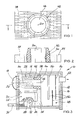
- the combustion device 10 according to the invention shown in FIGS. 1, 2 and 3 is present within an outer shell 12.
- the outer shell 12 is in turn covered on the inside by heat exchanger surfaces 14.
- a combustion chamber 16 is formed in an inner partial region - on the left in FIG. 3.
- This combustion chamber has a sectional head blower 18 on its left outer wall.
- the gas mass present in the combustion chamber 16 can be set in an endless rotation about a central axis 20.
- the axis of this gas roller 22 coincides approximately with the axis of rotation 20 of the blower 18.
- a space 26 with a furnace for burning combustible material 28 is present, separated by a horizontal ceiling 24.
- the two rooms 26, 16 are only connected to one another by an opening 30 provided in the ceiling 24.
- the firing material 28 is present within a trough 32 formed in the space 26 and is fed there from the outside via a feed device 34.
- a partition 38 is formed in the region of the combustion chamber 16.
- the partition 38 is pierced by a so-called flame tube 40, the front collar 42 of which protrudes into the combustion chamber 16 and protrudes into the center 44 of the roller 22.
- the collar 42 thus forms the opening region of the flame tube 40 which projects into the combustion chamber 16.
- the other end 46 of this flame tube 40 opens into a further space 48 which is equipped with a plurality of heat exchanger surfaces 50. The gas flowing into the space 48 through the flame tube 40 sweeps along the heat exchanger surfaces 50 and then leaves the outer shell 12 through an exhaust gas tube 52.
- the combustible material 28 present in the room 26 gasifies by burning within the room 26. This gasification creates a certain excess pressure in the room 26. This excess pressure is reduced through the opening 30 in the direction of the combustion chamber 16. Within the combustion chamber 16, the gases flowing in through the opening 30 from the space 26 are completely burned out.
- the mass of gas present in the combustion chamber 16 is displaced into a fire roller 22 with the aid of the link head blower 18.
- This fire roller rotates on its periphery at a high speed of about 40 to 50 m per second.
- the gas roller 22, which is set in endless rotation, is heavily loaded with dust or other not yet burned particles in its peripheral region due to the gas density prevailing there.
- the fire roller 22 is limited by the partition 38 in its axial extent.
- the peripheral regions of the roller 22 abut the partition 38 and thus do not strike the interior of the flame tube 40.
- the dust particles present in the outer regions of the roller 22 are thrown against the partition 38, whereby they disintegrate into smaller particles. This will promote their subsequent further combustion within the fire roller.
- the low-dust hot gas mass flows out of the Center 44 of the roller 22 through the flame tube 46 into the space 48 with the heat exchangers 50.
- This flow behavior is brought about by the vacuum present in the combustion chamber 16 via the exhaust tube 52.
- the link head blower 18 also creates a negative pressure within the combustion chamber 16, which supports the outflow behavior through the flame tube 40.
- the complete combustion of the existing particles within the combustion chamber 16 is achieved by the intimate mixing of air and hot gas with the help of the roller 22. Due to the air flow along the roller, these particles have a sufficiently long dwell time within the combustion phase.
- the ceiling 24 has the advantage that the underpressure forming in the combustion chamber 16 does not also have a full effect in the space 26 with the furnace for the firing material 28.
- the kiln 28 can therefore burn under excess pressure.
- a streak-like outflow of the heavily dust-laden flames arising during the combustion of the combustion material 28 into the combustion chamber 16 is therefore effectively prevented.
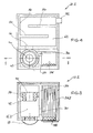
- the combustion chamber 16 and the space 26 with the furnace are arranged one below the other, in the combustion device 10.2, the combustion chamber 16.2 and the space 26.2 with the one shown in FIGS Furnace arranged side by side.
- the two rooms 16.2 and 26.2 are connected to one another only by an opening 30 which, because of the two rooms 16.2 and 26.2 arranged next to one another, is not present in a ceiling but in a wall 54.
- a grate 56 for supporting the combustible material to be burned is shown schematically. Firing material can be stored in room 26.2 via a firing door 58.
- a link head blower 18 is present in the combustion chamber 16: 2.
- the flame tube 40 with its collar 42 projecting into the combustion chamber 16.2 is arranged opposite the fan 18.
- the outer jacket regions of the gas roller generated by the link head blower 18 penetrate a partition wall 38 surrounding the flame tube and thus not into the interior of the flame tube 40.
- the flow conditions for the fuel gases are thus similar to that in FIGS 3 shown combustion device 10.
- the hot gases flow after passing through a flame channel 60 into another room 62 located above the combustion chamber 16.2 and the room 26.2 with the furnace, which is equipped with a plurality of heat exchanger surfaces 50.
- the gases are led out of the space 62 via an exhaust pipe 52.
- FIG. 6 shows a burning device 10.3 which can be used in the baking trade in the present example.
- the combustion chamber 16.3 is oriented obliquely upwards in space.
- the gas roller generated by the link head blower 18 present in the combustion chamber 16.3 thus flows obliquely upwards.
- the collar 42 projecting into the combustion chamber 16.3 ensures that only the dust-free inner regions of the roller can flow out through the flame tube 40 out of the combustion chamber 16.3.
- This space 64 communicates with the interior of the combustion chamber 16.3 via an opening (not shown in FIG. 6).
- the operation of this burner 10.3 corresponds to the burners 10 and 10.2 described above.
- the hot gases After leaving the flame tube 40, the hot gases enter a flame channel 66. From there, they can optionally be introduced into two ovens 68, 70.
- the supply of hot gases into the interior of the ovens 68, 70 can be regulated or limited in time by means of the shut-off devices 72, 74 connected upstream of the ovens 68, 70.
- the gases continue to flow out of the flame channel 66 through a chimney 76 after opening a shut-off member 75.
- the burner 10.3 can be retrofitted to existing ovens, for example as part of renovation projects. Due to the high burning power of the device according to the invention and the variations in the burning power which are possible within wide limits, optimum heating of downstream ovens or of other heat consumers is possible. If heating heat is not required, the heating power can be reduced very quickly and within wide limits by regulating the speed of the link head blower 18. On the other hand, by increasing the speed of the link head housing 18, conversely, it is also possible to very quickly start up from a low part-load operation to full load.
- both the speed of the rotating fire roller and the gasification phase in the fire can be achieved Increase or reduce room 26.2 because the necessary combustion air can always be added. This process is known in the forge fire, where it is generated by a bellows.
- FIG. 7 shows a combustion device 10.4, which has a combustion chamber 16.4, in which combustion of the combustion material also takes place at the same time.
- the combustion chamber 16.4 in turn has a sectional head blower 18 and, opposite this, the flame tube 40 leading out of the combustion chamber 16.4 with the collar 42 projecting freely into the combustion chamber 16.4. In the area of this flame tube 40, the combustion chamber 16.4 is separated by a partition 38 (see FIG. 3). completed.
- a pilot burner 80 is provided below the link head blower 18. Fuels such as chips, sawdust or the like are blown into the combustion chamber 16.4 from above through a feed channel 82. With the help of the pilot burner 80, these fuels can be burned within the combustion chamber 16.4. With the aid of the link head blower 18, the above-described fire roller 22 can then also be formed in the combustion chamber 16.4. Through the flame tube 40, practically dust-free gases also flow, as in the combustion devices described above, into downstream rooms, not shown, with heat exchanger surfaces.
- the burner 10.4 is preferably used for fine-grained, dry fuels such as shavings and dusts, since the fuel is mixed directly with the carrier air into the rotating fire roller.
- the burnout takes place in a sufficient dwell time since the fire roller flows through the combustion chamber in a spiral.
- a rust surface is not necessary here; the carrier air is also combustion air.
Abstract
Description
Die Erfindung betrifft eine Vorrichtung zum Verbrennen von Bio- und Feststoffmassen. Für Heizzwecke zu verwendende Biomassen sind beispielsweise Holzabfälle wie Späne, Sägemehl, Holzpreßpellets und dergleichen, die vor allem in der holzverarbeitenden Industrie in großem Umfang anfallen. Brennbare Feststoffmassen sind beispielsweise Holzmüllpellets, Schlammrückstände und sonstige verunreinigte Feststoffe. Die Wärmegewinnung aus derartigen Brennmaterialien ist wegen der damit verbundenen Umweltbelastung recht problematisch.The invention relates to a device for burning bio and solid masses. Biomasses to be used for heating purposes are, for example, wood waste such as shavings, sawdust, wood press pellets and the like, which accumulate on a large scale especially in the woodworking industry. Combustible solid masses include wood waste pellets, sludge residues and other contaminated solids. The generation of heat from such fuels is quite problematic because of the associated environmental pollution.
Die Art der Beschaffenheit des Brennstoffes setzt bestimmte Anforderungen in der Gestaltung der Brennvorrichtung. Für Feststoffe werden Rost-und Unterschubfeuerungen mit einem kompakten Glutbett bevorzugt angewendet. Leicht- und Schwerölfeuerungen mit Gebläsebrenner benötigen dagegen keinen Rost, diese Brennkammern werden daher bevorzugt in horizontaler Bauweise betrieben.The nature of the fuel places certain requirements on the design of the combustion device. Rust and underfeed firing with a compact ember bed are preferred for solids. Light and heavy oil firing systems with forced draft burners, on the other hand, do not require rust, which is why these combustion chambers are preferably operated in a horizontal design.
Alle diese Brennvorrichtungen haben gemeinsam, daß die Brennkammern mit nachgeschalteten Wärmetauscherflächen kommunizieren. Die Verbindung zwischen der Brennkammer und dem Raum mit den Wärmetauscherflächen ist teilweise mit und teilweise ohne kanalmäßiger Verengung ausgebildet.All of these combustion devices have in common that the combustion chambers communicate with downstream heat exchanger surfaces. The connection between the combustion chamber and the room with the heat exchanger surfaces is partly designed with and partly without a channel narrowing.
Feststoffbrennkammern verfügen über eine Rostfläche, auf der das Brennmaterial lagert. Die Brennkammern sind überwiegend rundum aus Schamotte gefertigt. Der Brennakt wird durch Zugabe von Primär- und ggf. Sekundärluft und ggf. durch Variieren des Unterdruckes gesteuert. Die sich dabei ausbildende Flamme füllt teilweise den gesamten Brennraum aus. Die Flammenspitzen werden zusammen mit den Heißgasen durch den natürlich vorhandenen oder mechanisch erzeugten Unterdruck in den Bereich der nachgeschalteten Wärmetauscherflächen gesaugt. Der Unterdruck kann beispielsweise durch das Anordnen eines Kamins auf natürliche Weise bewirkt werden.Solid fuel combustion chambers have a grate surface on which the fuel is stored. The combustion chambers are mostly made of chamotte all around. The firing cycle is controlled by adding primary and possibly secondary air and, if necessary, by varying the negative pressure. The flame that forms partially fills the entire combustion chamber. The flame tips are sucked together with the hot gases through the naturally existing or mechanically generated negative pressure into the area of the downstream heat exchanger surfaces. The negative pressure can, for example, be brought about naturally by arranging a fireplace.
Der bis zum Glutbett anstehende Unterdruck beeinflußt den Brennprozeß nachteilig. Es läßt sich nämlich nicht verhindern, daß die Heißgasflammen strähnenartig den Brennraum verlassen. Verbrannte und nicht verbrannte Staubpartikel werden dabei aus dem Brennraum mitgerissen und in den Bereich der Wärmetauscherflächen und weiter in den Bereich der Atmosphäre geleitet, wo sie die Umwelt belasten.The underpressure up to the ember bed adversely affects the burning process. It cannot be prevented that the hot gas flames leave the combustion chamber like strands. Burned and unburned dust particles are entrained from the combustion chamber and directed into the area of the heat exchanger surfaces and further into the area of the atmosphere, where they pollute the environment.
Bei ÖI- oder Gasgebläsebrennern ist die Flamme kompakt. Durch zwangsgeführte Verbrennungsluftzugabe, abgestimmt auf die Brennstoffmenge, wird ein totaler Ausbrand im Brennraum erreicht.The flame is compact in oil or gas fan burners. A total burnout in the combustion chamber is achieved by the forced addition of combustion air, matched to the amount of fuel.
Aus der PCT WO 90/14558 ist eine Brennvorrichtung der eingangs genannten Art bekannt, bei der sich mit Hilfe eines speziellen Gebläserades eine Gas- bzw. Feuerwalze im Brennraum herstellen läßt. Durch diese wirbelsturmartige Gasströmung kann eine sehr gute Verbrennung der verbrennbaren Partikel erreicht werden. Allerdings läßt sich nicht verhindern, daß die Flammenspitzen dieser walzenartigen Gasströmung aus dem Brennraum herauslecken. Das bedeutet, daß auch mit diesem Gebläserad verbrannte und nicht verbrannte Staubpartikel mit den Flammen aus dem Brennraum herausgerissen werden können.From PCT WO 90/14558 a combustion device of the type mentioned is known, in which a gas or fire roller can be produced in the combustion chamber with the aid of a special impeller. A very good combustion of the combustible particles can be achieved by means of this cyclone-like gas flow. However, it cannot be prevented that the flame tips of this roller-like gas flow leak out of the combustion chamber. This means that even with this fan wheel burned and unburned dust particles can be pulled out of the combustion chamber with the flames.
Der Erfindung liegt die Aufgabe zugrunde, ausgehend von dem vorstehend beschriebenen Stand der Technik eine verbesserte Vorrichtung zum Verbrennen von Bio- und Feststoffmassen anzugeben.The invention has for its object to provide an improved device for burning bio and solid masses starting from the prior art described above.
Die erfindungsgemäße Vorrichtung besitzt eine Brennkammer, eine Feuerungsstätte, einen der Brennkammer nachgeschalteten Raum mit wärmetauscherflächen, eine Verengung zwischen Brennkammer und diesem nachgeschalteten Raum, sowie ein Gebläserad zum Erzeugen einer Gas- bzw. Feuerwalze in der Brennkammer, wobei sich diese Vorrichtung erfindungsgemäß dadurch auszeichnet, daß die Verengung Teil eines Kanals ist, dessen einer Mündungsbereich frei in den Brennraum hineinkragt, und daß dessen Mündung in das Innere der Gas- bzw. Feuerwalze gerichtet ist. Diese Mündung kann sowohl auf das Gebläserad hingerichtet, als auch von demselben weggerichtet sein.The device according to the invention has a combustion chamber, a furnace, a space downstream of the combustion chamber with heat exchanger surfaces, a constriction between the combustion chamber and this space downstream, and an impeller for generating a gas or fire roller in the combustion chamber, this device being characterized according to the invention, that the constriction is part of a channel, one mouth area of which projects freely into the combustion chamber, and that its mouth is directed into the interior of the gas or fire roller. This mouth can be either directed towards the fan wheel or directed away from it.
Diese Vorrichtung hat den großen Vorteil, daß die durch das Gebläserad erzeugte wirbelsturmartige Gasströmung mit ihren äußeren, in ihrem Peripheriebereich gelegenen Gasmantelbereichen nicht durch die Verengung hindurch und damit aus der Brennkammer herausgeführt wird. Herausgeführt aus der Brennkammer und den Wärmetauscherflächen zugeführt werden nur die im Inneren der Gas- bzw. Feuerwalze vorhandenen, extrem staubfreien heißen Gase.This device has the great advantage that the cyclone-like gas flow generated by the impeller with its outer gas jacket regions located in its peripheral region is not passed through the constriction and thus out of the combustion chamber. Only the extremely dust-free hot gases present in the interior of the gas or fire roller are led out of the combustion chamber and the heat exchanger surfaces.
Feuerungsanlagen, die mit Brennstoffen betrieben werden, welche durch die Bearbeitung des Holzes viele kleine Partikel organischer Herkunft wie Staub und ähnliches beinhalten, neigen nämlich zu hohem Staubaustrag. Feuerungsanlagen, denen Kalk zur Schadgaseinbindung in die Brennkammer eingeblasen werden, werden durch die Staubfracht im Wärmetauscherbereich stark belastet. Diese Staubbelastung ist mit der erfindungsgemäßen Vorrichtung praktisch ausgeschlossen. Die Staubfracht wird sich nämlich bei der Ausbildung der Gas- bzw. Feuerwalze im äußeren Bereich dieser Walze bilden; diese äußeren Walzenbereiche gelangen aber nicht durch die Verengung hindurch aus dem Brennraum heraus. Diese äußeren Bereiche streichen vielmehr über den Mündungsbereich der aus dem Brennraum herausführenden Kanal hinweg.Firing systems that run on fuels that contain many small particles of organic origin such as dust and the like due to the processing of the wood tend to have a high dust discharge. Combustion systems, where lime is blown into the combustion chamber to incorporate harmful gas, are heavily loaded by the dust load in the heat exchanger area. This dust exposure is practically excluded with the device according to the invention. The dust load is namely in the formation of the gas or fire roller in the outer loading rich form this roller; however, these outer roller regions do not come out of the combustion chamber through the constriction. Rather, these outer areas sweep over the mouth area of the channel leading out of the combustion chamber.
Nach einer wesentlichen Weiterbildung der Erfindung kann der Kanal innerhalb einer den Brennraum begrenzenden Trennwand vorhanden sein. Die Gas- bzw. Feuerwalze kann sich mit ihren äußeren Peripheriebereichen dann im Umfeld des in des Brennraum hineinragenden Kanals totlaufen, so daß durch das Aufprallen der Staubfracht an dem den Mündungsbereich des Kanals umgebenden Bereich der Trennwand ein totales Ausbrennen der Heißgase bewirkt wird. Änderungen während des Brennprozesses, die beispielsweise durch die Brennstoffzusammensetzung entstehen, können durch Drehzahlveränderungen am Antriebsmotor des Gebläserades berücksichtigt werden.According to an essential development of the invention, the channel can be present within a partition wall delimiting the combustion chamber. The gas or fire roller can then run dead with its outer peripheral areas in the vicinity of the channel protruding into the combustion chamber, so that a total burnout of the hot gases is caused by the impact of the dust load on the area of the partition wall surrounding the mouth area of the channel. Changes during the combustion process, for example caused by the fuel composition, can be taken into account by changing the speed of the drive motor of the fan wheel.
Durch die Begrenzung der Brennkammer mittels einer solchen Trennwand mit stark eingeschränkter Öffnung, werden beim Anfahren der Brennvorrichtung und damit in deren Startphase die nachteiligen CO-Bildungen erheblich reduziert. Die nachteiligen Temperaturschwankungen nach dem Abschalten der Brennvorrichtung und das dabei erfolgende unerwünschte Abkühlen der Schamottewände werden zum Vorteil im Temperaturgefälle erheblich verlangsamt.By delimiting the combustion chamber by means of such a partition with a greatly restricted opening, the disadvantageous CO formation is considerably reduced when the combustion device is started up and thus in the starting phase. The disadvantageous temperature fluctuations after the combustion device is switched off and the undesired cooling of the fireclay walls taking place thereby are considerably slowed down in the temperature gradient.
Der alkalische Staub, mit dem das Heißgas beladen sein kann, reagiert mit den Schadstoffen HCI, S02. Die entstehenden Gips-Anhydridpartikel werden durch die herrschende Radialströmung an die Peripherie des Brennraumes getragen und können durch Ascheräumer dem Brennraum entnommen werden.The alkaline dust with which the hot gas can be loaded reacts with the pollutants HCI, S0 2 . The resulting gypsum anhydride particles are carried to the periphery of the combustion chamber by the prevailing radial flow and can be removed from the combustion chamber by ash cleaners.
Die Gestaltung der Brennkammer kann eckig oder rund sein. Die Brennerkammer kann ferner vertikal, horizontal oder schräg im Raum ausgerichtet sein. Die Gestaltung ist in weiten Grenzen beliebig; Voraussetzung einer optimalen Wirkungsweise ist allerdings, daß die kanalartige Verengung in das Innere der Gas- bzw. Feuerwalze einmünden kann. Durch die zusätzliche Anordnung der vorstehend bereits erwähnten Trennwand kann nicht nur verhindert werden, daß Staubpartikel aus der Brennkammer herausströmen können, sondern kann auch ein optimales Verbrennen dieser Staubpartikel erreicht werden. Es wird somit ein völlig neues Brennverhalten innerhalb einer Brennkammer erreicht.The design of the combustion chamber can be square or round. The burner chamber can also be aligned vertically, horizontally or obliquely in the room. The design is arbitrary within wide limits; A prerequisite for an optimal mode of operation is, however, that the channel-like constriction can open into the interior of the gas or fire roller. The additional arrangement of the partition mentioned above can not only prevent dust particles from flowing out of the combustion chamber, but also an optimal combustion of these dust particles can be achieved. A completely new combustion behavior is thus achieved within a combustion chamber.
Die endlos rotierende homogene Gasmasse, die in der Brennkammer erzeugt werden kann, wird durch den von außen in den Brennraum hinein wirkenden Unterdruck abgesaugt und den Wärmetauschern zugeführt.The endlessly rotating, homogeneous gas mass that can be generated in the combustion chamber is drawn off by the negative pressure acting from outside into the combustion chamber and fed to the heat exchangers.
Anlagen älterer Bauart können mit der erfindungsgemäßen Vorrichtung saniert werden. Damit können nachweislich auch bei solchen älteren Anlagen die verschärften TA-Luftwerte eingehalten werden.Systems of older design can be renovated with the device according to the invention. As a result, the stricter TA air values can be demonstrably maintained even in such older systems.
Eine wesentliche Weiterbildung der Erfindung zeichnet sich dadurch aus, daß Brennkammer und Vergasungskammer, d. h. der Raum mit der Feuerungsstätte, von der Brennkammer getrennt ausgebildet werden. Die Feuerungsstätte kommuniziert mit der Brennkammer lediglich über einen relativ kleinen Öffnungsbereich. Dies hat den großen Vorteil, daß Staub- und Festpartikel im Bereich der Feuerungsstätte zurückgehalten werden, weil der Vergasungsakt im Druckbereich und nicht in der Brennkammer, wo Unterdruck herrscht, stattfinden kann. Der von außen in die Brennkammer hineinwirkende Unterdruck herrscht damit nicht zwangsläufig auch gleichzeitig im Bereich der Feuerungsstätte. Dies ermöglicht eine besonders gute Vergasung der Brennmaterialien. Außerdem werden in der Brennkammer die restlichen Kohlenwasserstoffpartikel mit Hilfe der Gas- bzw. Feuerwalze total ausgebrannt. Dieser Ausbrand wird durch die innige Vermischung von Luft und Heißgas über eine längere Verweilzeit hinweg bewirkt. Dies ist für einen optimalen Ausbrand unbedingt erforderlich.An essential development of the invention is characterized in that the combustion chamber and gasification chamber, i. H. the room with the furnace must be designed separately from the combustion chamber. The furnace only communicates with the combustion chamber over a relatively small opening area. This has the great advantage that dust and solid particles are retained in the area of the furnace, because the gasification act can take place in the pressure area and not in the combustion chamber, where there is negative pressure. The negative pressure acting from the outside into the combustion chamber does not necessarily also exist in the area of the furnace at the same time. This enables particularly good gasification of the fuel. In addition, the remaining hydrocarbon particles in the combustion chamber are totally burned out with the help of the gas or fire roller. This burnout is caused by the intimate mixing of air and hot gas over a longer residence time. This is essential for optimal burnout.
Das räumliche Trennen der Feuerungsstätte von der Brennkammer bewirkt, daß der durch das Gebläserad in der Brennkammer erzeugte und/oder der von außen her einwirkende Unterdruck seine Unterdruckwirkung nicht auch in dem Bereich der Feuerungsstätte ausüben kann. Dadurch wiederum ist die Strähnenbildung der von der Feuerungsstätte wegzüngelnden Flammen in den Brennraum hinein nicht mehr möglich. Als weiteren Vorteil erweist es sich, daß die im Stand der Technik unerwünschten hohen NOx-Werte erheblich verringert werden können, da hohe Brennkammertemperaturen nicht mehr nötig sind; die ganze Brennkammer wird nämlich bei der erfindungsgemäßen Vorrichtung von der homogenen Gasmasse gleichmäßig durchströmt.The spatial separation of the furnace from the combustion chamber has the effect that the vacuum generated by the fan wheel in the combustion chamber and / or the external pressure acting from outside cannot also exert its vacuum effect in the region of the furnace. As a result, streaking of the flames that are to be blown away from the furnace into the combustion chamber is no longer possible. A further advantage is that the high NO x values which are undesirable in the prior art can be considerably reduced since high combustion chamber temperatures are no longer necessary; the entire combustion chamber is flowed through uniformly by the homogeneous gas mass in the device according to the invention.
Die erfindungsgemäße Vorrichtung hat den weiteren Vorteil, daß mehrere derartige Brennkammern und damit Brennvorrichtungen an einen Sammelkanal angeschlossen werden können. Erst von diesem Sammelkanal aus strömen die Heißgase dann in nachgeschaltete, auch mehrere Räume mit Wärmetauschern. Diese Anordnung ermöglicht einen problemlosen Teillastbetrieb, da einzelne Brennereinheiten problemlos abgeschaltet und beispielsweise renoviert werden können. Dadurch kann eine totale Abschaltung der Feuerungsanlage zu Reperaturzwecken umgangen werden.The device according to the invention has the further advantage that a plurality of such combustion chambers and thus combustion devices can be connected to a collecting duct. It is only from this collecting duct that the hot gases then flow into downstream, also several rooms with heat exchangers. This arrangement enables problem-free part-load operation, since individual burner units can be switched off without problems and, for example, renovated. This means that a total shutdown of the firing system for repair purposes can be avoided.
Das Betreiben der Feuerungsanlage im Teillastbetrieb ermöglicht darüber hinaus auch ein problemloses Steigern der Wärmeleistung. Während durch Anordnung des Gebläserades eine Steuerung der Heizleistung innerhalb einer einzigen Brennkammer möglich ist, läßt sich durch das Zu-und Abschalten mehrerer derartiger Brennkammern eine in weiten Grenzen optimale Anpassung der erzeugten Wärmeleistung an die jeweiligen Vorgaben und Anforderungen erreichen.Operating the combustion system in part-load mode also enables problem-free increases in thermal output. While by arranging the impeller a tax heating power within a single combustion chamber is possible, by switching a plurality of such combustion chambers on and off, an optimal adaptation of the generated heat output to the respective specifications and requirements can be achieved within wide limits.
Weitere Merkmale und Vorteile der Erfindung sind den in den Ansprüchen weiterhin aufgeführten Merkmalen sowie den nachfolgenden Ausführungsbeispielen zu entnehmen.Further features and advantages of the invention can be found in the features further specified in the claims and in the following exemplary embodiments.
Die Erfindung wird im folgenden anhand der in der Zeichnung dargestellten Ausführungsbeispiele näher beschrieben und erläutert. Es zeigen:
- Fig. 1 eine Draufsicht auf den Mündungsbereich der aus einer Brennkammer herausführenden kanalartigen Verengung bei einer erfindungsgemäßen Vorrichtung,
- Fig. 2 einen Querschnitt entsprechend Linie I-I der Fig. 1,
- Fig. 3 einen Vertikalschnitt einer anderen erfindungsgemäßen Vorrichtung mit übereinander angeordneter Brennkammer und Feuerungsstätte,
- Fig. 4 einen Vertikalschnitt durch eine weitere erfindungsgemäße Vorrichtung mit nebeneinanderliegender Brennkammer und Feuerungsstätte,
- Fig. 5 einen Horizontalschnitt durch die Vorrichtung gemäß Fig. 4,
- Fig. 6 eine schematisierte, teilweise geschnittene Seitenansicht einer weiteren Brennvorrichtung mit schräg angeordneter Brennkammer und mehreren nachgeschalteten Backöfen,
- Fig. 7 einen Vertikalschnitt einer weiteren Vorrichtung mit einem öl- bzw. gasbefeuerten Zündbrenner.
- 1 is a plan view of the mouth area of the channel-like narrowing leading out of a combustion chamber in a device according to the invention,
- 2 shows a cross section along line II of FIG. 1,
- 3 shows a vertical section of another device according to the invention with a combustion chamber and furnace located one above the other,
- 4 shows a vertical section through a further device according to the invention with a combustion chamber and furnace located next to one another,
- 5 shows a horizontal section through the device according to FIG. 4,
- 6 is a schematic, partially sectioned side view of a further combustion device with an inclined combustion chamber and a plurality of baking ovens connected downstream,
- Fig. 7 is a vertical section of a further device with an oil- or gas-fired pilot burner.
Die in den Fig. 1, 2 und 3 dargestellte erfindungsgemäße Brennvorrichtung 10 ist innerhalb einer Außenhülle 12 vorhanden. Die Außenhülle 12 ist ihrerseits innen von Wärmetauscherflächen 14 bedeckt.The
In einem - in Fig. 3 linken oberen - inneren Teilbereich ist eine Brennkammer 16 ausgebildet. Diese Brennkammer besitzt an ihrer linken Außenwand ein Gliederkopfgebläse 18. Mit Hilfe dieses Gebläses 18 läßt sich die in der Brennkammer 16 vorhandene Gasmasse in eine endlose Rotation um eine Mittelachse 20 versetzen. Die Achse dieser Gaswalze 22 fällt in etwa mit der Drehachse 20 des Gebläses 18 zusammen.A
Unterhalb der Brennkammer 16 ist durch eine horizontale Decke 24 getrennt ein Raum 26 mit einer Feuerungsstätte zum Verbrennen von Brenngut 28 vorhanden. Die beiden Räume 26, 16 sind lediglich durch eine in der Decke 24 vorhandene Öffnung 30 miteinander verbunden. Das Brenngut 28 ist innerhalb einer im Raum 26 ausgebildeten Mulde 32 vorhanden und wird dorthin über eine Zufuhreinrichtung 34 von außen her zugeführt.Below the
In Verlängerung einer den Raum 26 seitlich begrenzenden Mauerwerkswand 36 ist im Bereich der Brennkammer 16 eine Trennwand 38 ausgebildet. Die Trennwand 38 wird von einem sogenannten Flammrohr 40 durchstoßen, dessen kragartig in die Brennkammer 16 hineinragender vorderer Kragen 42 in das Zentrum 44 der Walze 22 hineinragt. Der Kragen 42 bildet damit den in die Brennkammer 16 hineinragenden Mündungsbereich des Flammrohres 40. Das andere Ende 46 dieses Flammrohres 40 mündet in einen weiteren Raum 48 ein, der mit mehreren Wärmetauscherflächen 50 ausgestattet ist. Das durch das Flammrohr 40 in den Raum 48 hineinströmende Gas streicht an den Wärmetauscherflächen 50 entlang und verläßt dann die Außenhülle 12 durch ein Abgasrohr 52.In the extension of a
Das in dem Raum 26 vorhandene Brenngut 28 vergast durch Abbrennen innerhalb des Raumes 26. Durch dieses Vergasen bildet sich im Raum 26 ein gewisser Überdruck aus. Dieser Überdruck baut sich durch die Öffnung 30 hin in Richtung Brennkammer 16 ab. Innerhalb der Brennkammer 16 werden die durch die Öffnung 30 aus dem Raum 26 hineinströmenden Gase vollständig ausgebrannt.The
Durch das Verbrennen des Brenngutes 28 wird mit Hilfe des Gliederkopfgebläses 18 die in der Brennkammer 16 vorhandene Gasmasse in eine Feuerwalze 22 versetzt. Diese Feuerwalze rotiert an ihrer Peripherie mit einer hohen Geschwindigkeit von etwa 40 bis 50 m pro Sekunde. Die in endlose Rotation versetzte Gaswalze 22 ist in ihrem Peripheriebereich durch die dort herrschende Gasdichte stark mit Staub oder sonstigen noch nicht verbrannten Partikeln beladen. Die Feuerwalze 22 wird durch die Trennwand 38 in ihrer axialen Ausdehnung begrenzt. Die Peripheriebereiche der Walze 22 stoßen auf die Trennwand 38 und treffen damit nicht in das Innere des Flammrohres 40 hinein. Durch das Flammrohr 40 werden dadurch nur die im Inneren der Walze 22 vorhandenen staubfreien Gasmassen aus der Brennkammer 16 herausgeführt. Die in den äußeren Bereichen der Walze 22 vorhandenen Staubpartikel werden gegen die Trennwand 38 geschleudert, wobei sie in kleinere Teilchen zerfallen. Dadurch wird ihre anschließende weitere Verbrennung innerhalb der Feuerwalze gefördert.By burning the material to be burned 28, the mass of gas present in the
Die staubarme Heißgasmasse strömt aus dem Zentrum 44 der Walze 22 durch das Flammrohr 46 in den Raum 48 mit den Wärmetauschern 50. Dieses Strömungsverhalten wird von dem über das Abgasrohr 52 in der Brennkammer 16 anstehenden Unterdruck bewirkt. Auch das Gliederkopfgebläse 18 bewirkt einen Unterdruck innerhalb der Brennkammer 16, der das Abströmverhalten durch das Flammrohr 40 hindurch unterstützt. Das vollständige Verbrennen der vorhandenen Partikel innerhalb des Brennraumes 16 wird durch die innige Vermischung von Luft und Heißgas mit Hilfe der Walze 22 erreicht. Durch die Luftströmung längs der Walze erreicht man eine ausreichend lange Verweilzeit dieser Partikel innerhalb der Verbrennungsphase.The low-dust hot gas mass flows out of the
Die Decke 24 hat den Vorteil, daß sich der in der Brennkammer 16 ausbildende Unterdruck nicht auch in voller Stärke im Raum 26 mit der Feuerungsstätte für das Brenngut 28 auswirkt. Das Brenngut 28 kann daher unter Überdruck abbrennen. Ein strähnenartiges Ausströmen der beim Verbrennen des Brenngutes 28 entstehenden stark staubbeladenen Flammen in die Brennkammer 16 hinein ist daher wirkungsvoll unterbunden. Damit trägt nicht nur die Ausbildung des Flammrohres 40 mit dem Kragen 42 sondern auch die Anordnung der Decke 24 zu einer optimalen Verbrennung wirkungsvoll bei.The
Während bei der Brennvorrichtung 10 (Fig. 1, 2, 3) die Brennkammer 16 und der Raum 26 mit der Feuerungsstätte untereinander angeordnet sind, sind bei der in den Fig. 4 und 5 dargestellten Brennvorrichtung 10.2, Brennkammer 16.2 und der Raum 26.2 mit der Feuerungsstätte nebeneinander angeordnet. Auch hier sind die beiden Räume 16.2 und 26.2 lediglich durch eine Öffnung 30 miteinander verbunden, die aufgrund der nebeneinander angeordneten beiden Räume 16.2 und 26.2 nicht in einer Decke sondern in einer Wand 54 vorhanden ist.While in the combustion device 10 (FIGS. 1, 2, 3) the
In dem Raum mit der Feuerungsstätte 26.2 ist ein Rost 56 zum Auflagern des zu verbrennenden Brenngutes schematisch dargestellt. Über eine Feuerungstür 58 läßt sich Brenngut in den Raum 26.2 einlagern.In the room with the furnace 26.2, a
In der Brennkammer 16:2 ist ein Gliederkopfgebläse 18 vorhanden. Dem Gebläse 18 gegenüber ist das Flammrohr 40 mit seinem in die Brennkammer 16.2 hineinragenden Kragen 42 angeordnet. Auch bei der Brennvorrichtung 10.2 dringen die äußeren Mantelbereiche der durch das Gliederkopfgebläse 18 erzeugten Gaswalze auf eine das Flammrohr umgebende Trennwand 38 und damit nicht in das Innere des Flammrohres 40. Die Strömungsverhältnisse für die Brenngase sind damit ähnlich wie bei der in den Fig. 1 bis 3 dargestellten Brennvorrichtung 10. Nach Verlassen des Flammrohres 40 strömen die heißen Gase nach Passieren eines Flammkanals 60 in einen über der Brennkammer 16.2 und dem Raum 26.2 mit der Feuerungsstätte gelegenen weiteren Raum 62, der mit mehreren Wärmetauscherflächen 50 ausgestattet ist. Über ein Abgasrohr 52 werden die Gase aus dem Raum 62 hinausgeführt.A
In Fig. 6 ist eine Brennvorrichtung 10.3 dargestellt, die im vorliegenden Beispielsfall im Bäckerhandwerk zur Anwendung kommen kann. Bei dieser Brennvorrichtung 10.3 ist die Brennkammer 16.3 schräg im Raum nach oben ausgerichtet. Die durch das in der Brennkammer 16.3 vorhandene Gliederkopfgebläse 18 erzeugte Gaswalze strömt also nach schräg oben. Auch hier ist durch den in die Brennkammer 16.3 hineinragenden Kragen 42 sichergestellt, daß nur die staubfreien inneren Bereiche der Walze durch das Flammrohr 40 hindurch nach außen aus der Brennkammer 16.3 herausströmen können.6 shows a burning device 10.3 which can be used in the baking trade in the present example. In this combustion device 10.3, the combustion chamber 16.3 is oriented obliquely upwards in space. The gas roller generated by the
Unterhalb der Brennkammer 16.3 ist ein Raum 64 mit der Feuerungsstätte vorhanden. Dieser Raum 64 kommuniziert über eine in Fig. 6 nicht näher dargestellte Öffnung mit dem Inneren der Brennkammer 16.3. Die Wirkungsweise dieser Brennvorrichtung 10.3 entspricht den vorstehend beschriebenen Brennvorrichtungen 10 und 10.2.Below the combustion chamber 16.3 there is a
Nach Verlassen des Flammrohres 40 gelangen die heißen Gase in einen Flammkanal 66. Von dort können sie wahlweise in zwei Backöfen 68, 70 eingeleitet werden. Mittels den Backöfen 68, 70 vorgeschalteter Absperrorganen 72, 74 läßt sich die Zufuhr von heißen Gasen in das Innere der Backöfen 68, 70 regulieren bzw. zeitlich begrenzen.After leaving the
Nach der Aufheizphase der Backöfen 68, 70 strömen die Gase nach Öffnen eines Absperrorgans 75 aus dem Flammkanal 66 weiter durch einen Kamin 76 ins Freie.After the heating phase of the
Mit der Brennvorrichtung 10.3 lassen sich mehrere Backöfen beheizen. Die Brennvorrichtung 10.3 kann nachträglich an vorhandene Backöfenanlagen beispielsweise im Rahmen von Sanierungsvorhaben nachträglich eingebaut werden. Aufgrund der hohen Brennleistung der erfindungsgemäßen Vorrichtung und der in weiten Grenzen möglichen Variationen der Brennleistung ist ein optimales Beheizen von nachgeschalteten Backöfen oder auch von sonstigen Wärmeverbrauchern möglich. Bei Nichtbedarf von Heizwärme kann durch Regulieren der Drehzahl des Gliederkopfgebläses 18 die Heizleistung sehr schnell und in weiten Grenzen heruntergefahren werden. Andererseits ist es durch Erhöhung der Drehzahl des Gliederkopfgehäuses 18 umgekehrt auch möglich, von einem niedrigen Teillastbetrieb sehr schnell auf volle Last hochzufahren. Durch die Drehzahlregelung des Gliederkopfgebläses 18 beispielsweise mit Hilfe eines Frequenzumrichters läßt sich je nach Wärmebedarf somit sowohl die Geschwindigkeit der rotierenden Feuerwalze als auch die Vergasungsphase im Feuerraum 26.2 steigern oder reduzieren, da immer die nötige Verbrennungsluft zugegeben werden kann. Bekannt ist dieser Vorgang ansich beim Schmiedefeuer, dort erzeugt durch einen Blasebalg.With the burning device 10.3, several ovens can be heated. The burner 10.3 can be retrofitted to existing ovens, for example as part of renovation projects. Due to the high burning power of the device according to the invention and the variations in the burning power which are possible within wide limits, optimum heating of downstream ovens or of other heat consumers is possible. If heating heat is not required, the heating power can be reduced very quickly and within wide limits by regulating the speed of the
Während bei der Darstellung gemäß Fig. 6 nur eine einzelne Brennvorrichtung zum Beheizen der Backöfen 68, 70 vorhanden ist, ist es ohne weiteres möglich, an den Flammkanal 66 mehrere derartige Brennvorrichtungen anzuschließen. Dadurch ist es möglich, die Heizleistung in noch größeren Bandbreiten zu variieren. So können problemlos eine oder mehrere vorhandenen Brennvorrichtungen abgeschaltet werden. Ein totales Abschalten der gesamten Feuerungsanlage zu Reparaturzwekken ist damit nicht mehr erforderlich, da ein Teillastbetrieb ohne Probleme jederzeit möglich ist.While there is only a single firing device for heating the
In Fig. 7 ist eine Brennvorrichtung 10.4 dargestellt, die eine Brennkammer 16.4 besitzt, in der gleichzeitig auch das Verbrennen des Brenngutes stattfindet.7 shows a combustion device 10.4, which has a combustion chamber 16.4, in which combustion of the combustion material also takes place at the same time.
Die Brennkammer 16.4 besitzt wiederum ein Gliederkopfgebläse 18 und diesem gegenüber das aus der Brennkammer 16.4 herausführende Flammrohr 40 mit dem in die Brennkammer 16.4 frei hineinkragenden Kragen 42. Im Bereich dieses Flammrohrs 40 ist die Brennkammer 16.4 durch eine Trennwand 38 (vgl. Fig. 3) abgeschlossen.The combustion chamber 16.4 in turn has a
Unterhalb des Gliederkopfgebläses 18 ist ein Zündbrenner 80 vorhanden. Von oben wird durch einen Zuführungskanal 82 Brennstoffe wie Späne, Sägemehl oder dergleichen in die Brennkammer 16.4 eingeblasen. Mit Hilfe des Zündbrenners 80 können diese Brennstoffe innerhalb der Brennkammer 16.4 zum Verbrennen gebracht werden. Mit Hilfe des Gliederkopfgebläses 18 kann dann ebenfalls in der Brennkammer 16.4 die vorstehend bereits beschriebene Feuerwalze 22 ausgebildet werden. Durch das Flammrohr 40 strömt ebenfalls wie bei den vorstehend beschriebenen Brennvorrichtungen praktisch staubfreie Gase in nachgeschaltete, nicht näher dargestellte Räume mit Wärmetauscherflächen.A
Die Brennvorrichtung 10.4 wird bevorzugt für feinkörnige, trockene Brennstoffe wie Späne und Stäube verwendet, da der Brennstoff durch Einblasen mit der Trägerluft unmittelbar der rotierenden Feuerwalze beigemischt wird. Der Ausbrand erfolgt in genügender Verweilzeit, da die Feuerwalze den Brennraum spiralförmig durchströmt. Eine Rostfläche ist hier nicht nötig; die Trägerluft ist zugleich Verbrennungsluft.The burner 10.4 is preferably used for fine-grained, dry fuels such as shavings and dusts, since the fuel is mixed directly with the carrier air into the rotating fire roller. The burnout takes place in a sufficient dwell time since the fire roller flows through the combustion chamber in a spiral. A rust surface is not necessary here; the carrier air is also combustion air.
Claims (10)
dadurch gekennzeichnet, daß
characterized in that
dadurch gekennzeichnet, daß
characterized in that
dadurch gekennzeichnet, daß dieser Mündungsbereich (42) des Kanals auf das Gebläserad (18) hingerichtet oder von dem Gebläserad (18) weggerichtet ist.3. Device according to claim 1 or 2,
characterized in that said mouth region (42) of the channel is directed towards the impeller (18) or away from the impeller (18).
dadurch gekennzeichnet, daß
characterized in that
dadurch gekennzeichnet, daß
characterized in that
dadurch gekennzeichnet, daß
characterized in that
dadurch gekennzeichnet, daß
characterized in that
dadurch gekennzeichnet, daß
characterized in that
dadurch gekennzeichnet, daß
characterized in that
dadurch gekennzeichnet, daß
characterized in that
Applications Claiming Priority (2)
| Application Number | Priority Date | Filing Date | Title |
|---|---|---|---|
| DE19914125047 DE4125047A1 (en) | 1991-07-29 | 1991-07-29 | DEVICE FOR HOT GAS MIXING AND DUST REDUCTION IN COMBUSTION CHAMBERS |
| DE4125047 | 1991-07-29 |
Publications (2)
| Publication Number | Publication Date |
|---|---|
| EP0525711A2 true EP0525711A2 (en) | 1993-02-03 |
| EP0525711A3 EP0525711A3 (en) | 1993-03-03 |
Family
ID=6437217
Family Applications (1)
| Application Number | Title | Priority Date | Filing Date |
|---|---|---|---|
| EP19920112832 Withdrawn EP0525711A3 (en) | 1991-07-29 | 1992-07-28 | Device for burning bio-masses and solid materials |
Country Status (2)
| Country | Link |
|---|---|
| EP (1) | EP0525711A3 (en) |
| DE (1) | DE4125047A1 (en) |
Cited By (4)
| Publication number | Priority date | Publication date | Assignee | Title |
|---|---|---|---|---|
| EP0751347A1 (en) * | 1995-06-29 | 1997-01-02 | Richard Kablitz & Mitthof GmbH | Furnace |
| EP1122495A1 (en) * | 2000-02-04 | 2001-08-08 | Paul Christian | Device for incinerating biomass material in pulverized and solid form |
| CN103615728A (en) * | 2013-11-06 | 2014-03-05 | 李观德 | Method and high-temperature pot and furnace device for combusting biomass in combustor in environment-friendly manner |
| CN103615729A (en) * | 2013-11-06 | 2014-03-05 | 李观德 | High-temperature environment-friendly burning method and device for harmless refuse treatment |
Citations (4)
| Publication number | Priority date | Publication date | Assignee | Title |
|---|---|---|---|---|
| GB2068516A (en) * | 1980-01-28 | 1981-08-12 | Volvo Flygmotor Ab | Incineration of and energy recovery from relatively incombustible waste especially rubber and plastic |
| EP0289355A2 (en) * | 1987-05-01 | 1988-11-02 | Utec B.V. | Methods and apparatus for the combustion of organic matter |
| EP0340859A1 (en) * | 1988-04-29 | 1989-11-08 | Machinefabriek G. van der Ploeg B.V. | Boiler |
| WO1990014558A1 (en) * | 1989-05-25 | 1990-11-29 | Christian, Paul | Device for burning bio-masses and solid materials |
-
1991
- 1991-07-29 DE DE19914125047 patent/DE4125047A1/en not_active Withdrawn
-
1992
- 1992-07-28 EP EP19920112832 patent/EP0525711A3/en not_active Withdrawn
Patent Citations (4)
| Publication number | Priority date | Publication date | Assignee | Title |
|---|---|---|---|---|
| GB2068516A (en) * | 1980-01-28 | 1981-08-12 | Volvo Flygmotor Ab | Incineration of and energy recovery from relatively incombustible waste especially rubber and plastic |
| EP0289355A2 (en) * | 1987-05-01 | 1988-11-02 | Utec B.V. | Methods and apparatus for the combustion of organic matter |
| EP0340859A1 (en) * | 1988-04-29 | 1989-11-08 | Machinefabriek G. van der Ploeg B.V. | Boiler |
| WO1990014558A1 (en) * | 1989-05-25 | 1990-11-29 | Christian, Paul | Device for burning bio-masses and solid materials |
Cited By (7)
| Publication number | Priority date | Publication date | Assignee | Title |
|---|---|---|---|---|
| EP0751347A1 (en) * | 1995-06-29 | 1997-01-02 | Richard Kablitz & Mitthof GmbH | Furnace |
| US5694868A (en) * | 1995-06-29 | 1997-12-09 | Michard Kablitz & Mitthof Gmbh | Furnace system with post combustion space |
| EP1122495A1 (en) * | 2000-02-04 | 2001-08-08 | Paul Christian | Device for incinerating biomass material in pulverized and solid form |
| CN103615728A (en) * | 2013-11-06 | 2014-03-05 | 李观德 | Method and high-temperature pot and furnace device for combusting biomass in combustor in environment-friendly manner |
| CN103615729A (en) * | 2013-11-06 | 2014-03-05 | 李观德 | High-temperature environment-friendly burning method and device for harmless refuse treatment |
| CN103615729B (en) * | 2013-11-06 | 2016-04-27 | 李观德 | Rubbish processing to be harmless high-temperature environmental-protection combustion method and device |
| CN103615728B (en) * | 2013-11-06 | 2016-10-05 | 李观德 | Biomass environment-friendly burner combustion method and high temperature pan-furnace device |
Also Published As
| Publication number | Publication date |
|---|---|
| EP0525711A3 (en) | 1993-03-03 |
| DE4125047A1 (en) | 1993-02-04 |
Similar Documents
| Publication | Publication Date | Title |
|---|---|---|
| DE60209759T2 (en) | COMBUSTION DEVICE | |
| EP3889502B1 (en) | Combustor arrangement for a biomass heating system | |
| CH626975A5 (en) | ||
| EP3789672B1 (en) | Biomass heating system with secondary air conduit, and components of same | |
| EP2058589A2 (en) | Boiler for solid fuel | |
| EP0588075B1 (en) | Combustion process and furnace for burning waste | |
| EP0409790A1 (en) | Combustion installation | |
| DE2721237A1 (en) | PROCEDURE FOR INCINERATION OF HIGHLY HUMID, PRIORLY VEGETABLE WASTE FUELS AND INCINERATOR FOR CARRYING OUT THE PROCESS | |
| EP0482306B1 (en) | Method and device for the combustion of wood chips generating fumes low in noxious substances under continuously controllable firing power | |
| EP0525711A2 (en) | Device for burning bio-masses and solid materials | |
| DE3705406C2 (en) | ||
| EP0473618B1 (en) | Device for burning bio-masses and solid materials | |
| DE19850376C2 (en) | Device for burning bio and solid masses with primary pollution reduction - CO, NOx and dust | |
| EP0952396B1 (en) | Device for burning particulate combustible material | |
| CH671822A5 (en) | Solid fuel fired boiler - has after burning chamber connected to primary combustion chamber by mixing tube | |
| AT412308B (en) | HEATING DEVICE | |
| EP4056900A1 (en) | Biomass heating system with an improved cleaning device | |
| DE3705153A1 (en) | Firing stove | |
| DE3524962C2 (en) | ||
| EP1122495B1 (en) | Device for incinerating biomass material in pulverized and solid form | |
| DE19743338A1 (en) | Combustion plant | |
| DE102019114571B4 (en) | Combustion optimization device for reducing emissions in flue gas, wood-burning oven with a combustion optimization device and its use | |
| EP0877201A1 (en) | Device for combustion of bio- and solid matter | |
| AT2112U1 (en) | COMBUSTION PLANT | |
| AT240499B (en) | Process for the combustion of solid, in particular small-grain fuels and a furnace for carrying out the process |
Legal Events
| Date | Code | Title | Description |
|---|---|---|---|
| PUAI | Public reference made under article 153(3) epc to a published international application that has entered the european phase |
Free format text: ORIGINAL CODE: 0009012 |
|
| PUAL | Search report despatched |
Free format text: ORIGINAL CODE: 0009013 |
|
| AK | Designated contracting states |
Kind code of ref document: A2 Designated state(s): AT CH DE ES LI |
|
| AK | Designated contracting states |
Kind code of ref document: A3 Designated state(s): AT CH DE ES LI |
|
| STAA | Information on the status of an ep patent application or granted ep patent |
Free format text: STATUS: THE APPLICATION IS DEEMED TO BE WITHDRAWN |
|
| 18D | Application deemed to be withdrawn |
Effective date: 19930904 |