EP1122495B1 - Device for incinerating biomass material in pulverized and solid form - Google Patents
Device for incinerating biomass material in pulverized and solid form Download PDFInfo
- Publication number
- EP1122495B1 EP1122495B1 EP01101502A EP01101502A EP1122495B1 EP 1122495 B1 EP1122495 B1 EP 1122495B1 EP 01101502 A EP01101502 A EP 01101502A EP 01101502 A EP01101502 A EP 01101502A EP 1122495 B1 EP1122495 B1 EP 1122495B1
- Authority
- EP
- European Patent Office
- Prior art keywords
- gas
- blower
- space
- wall
- dust
- Prior art date
- Legal status (The legal status is an assumption and is not a legal conclusion. Google has not performed a legal analysis and makes no representation as to the accuracy of the status listed.)
- Expired - Lifetime
Links
Images


Classifications
-
- F—MECHANICAL ENGINEERING; LIGHTING; HEATING; WEAPONS; BLASTING
- F23—COMBUSTION APPARATUS; COMBUSTION PROCESSES
- F23G—CREMATION FURNACES; CONSUMING WASTE PRODUCTS BY COMBUSTION
- F23G5/00—Incineration of waste; Incinerator constructions; Details, accessories or control therefor
- F23G5/50—Control or safety arrangements
-
- F—MECHANICAL ENGINEERING; LIGHTING; HEATING; WEAPONS; BLASTING
- F23—COMBUSTION APPARATUS; COMBUSTION PROCESSES
- F23G—CREMATION FURNACES; CONSUMING WASTE PRODUCTS BY COMBUSTION
- F23G5/00—Incineration of waste; Incinerator constructions; Details, accessories or control therefor
- F23G5/32—Incineration of waste; Incinerator constructions; Details, accessories or control therefor the waste being subjected to a whirling movement, e.g. cyclonic incinerators
-
- F—MECHANICAL ENGINEERING; LIGHTING; HEATING; WEAPONS; BLASTING
- F23—COMBUSTION APPARATUS; COMBUSTION PROCESSES
- F23G—CREMATION FURNACES; CONSUMING WASTE PRODUCTS BY COMBUSTION
- F23G7/00—Incinerators or other apparatus for consuming industrial waste, e.g. chemicals
- F23G7/10—Incinerators or other apparatus for consuming industrial waste, e.g. chemicals of field or garden waste or biomasses
-
- F—MECHANICAL ENGINEERING; LIGHTING; HEATING; WEAPONS; BLASTING
- F23—COMBUSTION APPARATUS; COMBUSTION PROCESSES
- F23G—CREMATION FURNACES; CONSUMING WASTE PRODUCTS BY COMBUSTION
- F23G2203/00—Furnace arrangements
- F23G2203/40—Stationary bed furnace
-
- F—MECHANICAL ENGINEERING; LIGHTING; HEATING; WEAPONS; BLASTING
- F23—COMBUSTION APPARATUS; COMBUSTION PROCESSES
- F23G—CREMATION FURNACES; CONSUMING WASTE PRODUCTS BY COMBUSTION
- F23G2209/00—Specific waste
- F23G2209/26—Biowaste
- F23G2209/261—Woodwaste
-
- F—MECHANICAL ENGINEERING; LIGHTING; HEATING; WEAPONS; BLASTING
- F23—COMBUSTION APPARATUS; COMBUSTION PROCESSES
- F23G—CREMATION FURNACES; CONSUMING WASTE PRODUCTS BY COMBUSTION
- F23G2900/00—Special features of, or arrangements for incinerators
- F23G2900/50007—Co-combustion of two or more kinds of waste, separately fed into the furnace
-
- F—MECHANICAL ENGINEERING; LIGHTING; HEATING; WEAPONS; BLASTING
- F23—COMBUSTION APPARATUS; COMBUSTION PROCESSES
- F23G—CREMATION FURNACES; CONSUMING WASTE PRODUCTS BY COMBUSTION
- F23G2900/00—Special features of, or arrangements for incinerators
- F23G2900/54402—Injecting fluid waste into incinerator
Definitions
- the invention relates to a device for burning of Organic dust and organic solids.
- Biomass used for heating and for thermal disposal are available, for example, piece wood, shavings, Sawdust, wood chips, biofin dusts and biowaste.
- the progressive development of manufacturing technologies in the woodworking industry has not just shortened Workpiece life, but also to a considerable extent resulted in finer, dusty production waste in the Industry and craft today account for 70 to 80% (Percent) of wood residues.
- Another user wood burning is the bakery trade. The burning such residues is a challenge to the Feuerungsbauer. The regularly used rust with additional Primary air addition achieved in most combustion plants no longer the required low emission levels.
- EP-A-0 877 201 A generic device of the type mentioned is known from EP-A-0 877 201. Between the helical gas flow generating blower device and the firing space fluidly connected thereto a channel-like mixing space formed to the Firebox opens. Comparable is also the EP-A-0 905 442.
- the invention is based on the object, starting from the As described above, a device for burning organic dust masses and organic solid matter specify the least polluting pollutants arise and be emitted.
- the downstream cross-sectional taper of the mixing chamber with the approximately central gas passage opening causes a Constriction of the mixed gas combustion air rotating in the mixing chamber.
- This constricted combustion air relaxes in the downstream firebox in one stable rotating fire roller.
- This fire roller can thereby targeted to the ember bed surface in the firebox be directed. This ultimately causes an optimal and rapid combustion of biomass in the firebox.
- the baffle plate formed in the present example as a heat shield may have a central opening.
- the gases flowing back from the combustion chamber into the mixing chamber are thus not completely deflected radially outwards on the baffle plate, but partly flow directly back into the blower device and then back into the mixing chamber via the annular space. This has a stabilizing effect on the rotating gas cylinder in the mixing chamber and can also be referred to as internal NO x reduction.
- the device according to the invention means for the woodworking Industry and the bakery trade a big one technical progress in terms of thermal Energy generation and disposal of the residues.
- Old and new biomass firings can be combined with the equipped device according to the invention or be retrofitted.
- a device according to the invention can with a through a frequency converter regulated link head blower according to EP 0 344 498 or with operated an impeller with perforated blading become.
- the fresh air can be sucked in the shaft flange area and be used for engine cooling.
- Fresh air can also supplied to the blower area via separate intake openings, rotated and compactly accelerated.
- the according to rotating fresh air is then over a Annulus fed to the mixing chamber, in addition to from the Combustion chamber recirculated hot gas mixed and then the Supplied combustion process.
- blower area and mixing room can be a component in itself firmly connected "gas mixer" arise.
- the Firebox is fluidly gas mixer downstream.
- the transition area or border area between this gas mixer tap and the firebox preferably formed water-cooled.
- the coldest zone This gas mixer is located in the blower area.
- the warmer zone lies in the mixing room.
- Large-area emerging gas swirl nozzle is the prevailing Accumulation heat (about 900 ° C (degrees Celsius)) of the downstream Firing room exposed.
- the in the mixing chamber radially rotating gas mass generates in the center one very strong gas vacuum - eye of an eddy current - what to a backflow of CO-containing hot gas from the firebox leads to the inner baffle plate, which for the sake of a increased thermal load formed as a heat shield can be.
- the CO-laden substream heats the gases in the Mixing room at about 200 to 300 ° C (degrees Celsius).
- the Temperature In the border area between mixing room and firebox lies the Temperature at about 500 ° C to 700 ° C (degrees Celsius).
- the communication zone created by the previously known link head blower the gas flow with the supply air or Ambient air is in the periphery of the annulus, on the inside of the chamber wall.
- the inventively created Communication zone is located with a significantly improved efficiency, however, at the end of the new existing mixing chamber according to a first embodiment of the invention in the cross-sectional area of the swirl nozzle acting gas passage opening in the region of a concentric Rejuvenation of the mixing room in its transition to Firing room, or according to another embodiment of the Invention in the annular gap of the gas passage opening containing annular wall.
- the hot gas roller thus produced leaves in the downstream, existing or retrofitted firing rooms a staufenlose Low-emission combustion of biomass in the control range from 30% to 100% with the necessary temperature mixing and dwell time too.
- By changing the cross sections from the inner heat shield or the swirl nozzle can the spiral radial flow in the firing areas the respective requirements, in particular the Location, shape and size of an ember bed to be adjusted.
- the each resulting spiral, rotating radial flow-type fire roller can last longer due to these changes and more constant or shorter and more unstable with respect to her Rotational form be designed.
- the device according to the invention can be vertical, horizontal or diagonally, as injection and / or underfeed firing be educated.
- a secondary air addition and part of a primary air addition can be done via the swirl nozzle, in one spirally rotating gas cylinder in the axial outflow direction towards the ember bed.
- Another primary air addition in the Front lower firebed area can be accessed via gas exhaust nozzles done in the front wall of the outer Heat shield can be placed. Your air jet can then end and act in the ember bed in the axial outflow direction, especially in the lower part of the ember bed.
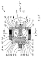
- a firing system 10 is used for burning organic dust masses and organic solids.
- the furnace 10 has a firing space 12, in the solid masses 14 (Fig. 6) can be burned.
- a gas mixer 20 produces a gas cylinder 90 and represents a compact unit, which in a in the Wall 22 of the furnace 10 existing breakthrough 24 is used gas-tight.
- the gas mixer 20 has an outer housing wall 26 which is in its central area is formed circular cylindrical and a mixing chamber 28th wrapped in a cylindrical shape.
- a central opening in which a shaft 32 rotatably mounted is, via a motor drive 34 about the longitudinal axis 36 of the gas-mixing mixer 20 are set in rotation can.
- On the shaft 32 are in the present case two rings attached by chain links 38, 40, which together with the Shaft 32 can rotate about the axis 36.
- the wreaths are movably attached to the shaft 32.
- Outflow side in the transition area between the blower area 46 and the mixing chamber 28, is a centric heat shield 50 available.
- the heat shield 50 On its inflow side is the heat shield 50 surrounded by a housing 52.
- In this case 52 projects into a conduit 54, which the fan area 46th and the back wall 30 pierces.
- the opening 56 of this Line 54 provides a suction for fresh air and Rezigas dar. Fresh air and Rezigas can so through the Line 42 (in the fan section 46) and through the line 54 (in the region of the housing 52 of the heat shield 50) each initiated.
- the housing 52 has opening slots 58 through which the in the housing 52 introduced mixture of fresh air and Rezigas can emerge radially in an annular space 60, the Heat shield 50 radially outwardly surrounds.
- the annulus 60 is so formed between the heat shield 50 and the housing wall 26 and adjusts the fluid connection to Mixing room 28 dar.
- annular wall 70 formed as an outer heat shield is.
- the annular wall 70 has a central opening 72. Die Inside the annular wall 70 is in a flowing transition connected to the housing wall 26. This on the ring wall 70th adjacent housing wall portion 78 is connected to the housing wall 26th integrally connected.
- the metallic in this case Housing wall 26 thus forms in the region of the annular wall 70 a inner lining of this annular wall 70.
- Fig. 1st right side of this ring wall 70 is the Furnace space 12, in particular of FIG. 6 schematically can be seen.
- full-surface Heat shield 50 is shown in the in Fig. 2 in section Heat shield 50.2 a central opening 62 available. This allows a certain flow compensation between the Blower area 46 and the mixing space 28 take place. Instead of an opening 62 can also be arranged a plurality of openings be.
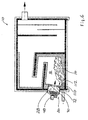
- furnace 10.5 are fed the bio-dust masses via a blowing-in line 18 (Arrow 16).
- the sparger 18 is in this embodiment Component of the gas mixer 20.
- the injection line 18 protrudes largely centrally through the Mixing chamber 28 through and ends in the region of the opening 72nd With her other end, she pierces the heat shield 50 and the housing 52 and ends outside the rear wall 30th
- the firing system 10 or 10.5 works following way:
- a rotating air roller is generated in the region of the annular space 60, which continues on the inside of the housing wall 26 through the mixing space 28 as a gas roller 90.
- this gas cylinder 90 experiences a central constriction (gas roller 90.2).
- this gas cylinder 90.2 relaxes more or less abruptly to the outside.
- a radially expanding hot gas roller (fire roller) 90.4 is created which ends above the ember bed of the solid mass 14 (FIG. 6). Due to the strong rotation of this gas cylinder 90, 90.2, 90.4 forms in the region of its axis of rotation, a significant negative pressure.
- a gas backflow (arrow 100) is effected which returns CO laden hot gas as a partial flow from the firing chamber 12 into the region of the mixing chamber 28.
- This gas recirculation 100 heats the gases in the mixing chamber to about 200 to 300 ° C (degrees Celsius), the gases in the region of the opening 72 to about 500 to 700 ° C.
- the gas recirculation 100 is completely deflected outwards (arrows 104) and mixes with the gas cylinder 90.
- FIG 2 FIG 2
- Openings 110 present through the air from the Mixing chamber 28 in the firing chamber 12 as a result of by the Gas roll 90 flow through the mixing chamber 28 generated gas flow can.
- the openings 110 are aligned so that this additionally directed into the firing chamber 12 gas flow (Primary air) in the direction of the solid mass 14 or whose ember bed 112 is directed.
- Fig. 7 is a compared to the embodiments shown in FIGS. 1 and 5 comparatively very thick wall 70.7 available. This allows a constricted longer in the flow direction permanent gas or fire roller 90.4 achieve.
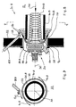
- Fig. 8 In the furnace 10.8 shown in Fig. 8 is the in the above-described furnace 10 existing Ring wall 70 as relatively far into the firing 12th protruding pipe or channel piece 70.8 formed. In addition, between this piece of pipe 70.8 and the combustion chamber 12 limiting wall 22 an annular gap 116 available.
- the injection line, in the Fig. 5 in the Mixing chamber 28 protrudes, is 10.8 in this furnace 10.8 outside the gas mixer 20 available by protrudes through the wall 22 and outside of the pipe section 70.8 ends directly in the firing chamber 12. Your end Injection nozzle for introducing coarse and in particular also Fine dust in the firing chamber 12, and thus its outlet opening 118, is aligned in the firing chamber 12 that the dust 120 is parallel to a pipe section 70.8 concentric can flow out surrounding circular cylinder.
- This furnace 10.8 is based on the knowledge that a coarse and fine dust combustion no constriction of Gas roller, as described in Figures 1 to 7 is needed.
- the ignition of coarse and fine dust 120 takes place immediately after leaving the injection line 18.8 and thus after flowing out of the outlet opening 118.
- the in the rotating gas or fire roller 90.8 in the firing chamber 12 immediately released heat accumulation allows a fast and optimal combustion without Grobasche- and Slag formation.
- the firing chamber 12 is due to the ruling high temperatures fireproof.
- the internal Rezigas recirculation and the NO x reduction are carried out in the same manner as in the ember bed furnace described above in connection with FIGS. 1 and 7.
- the externally recirculated flue gas with its oxygen content contributes all the more to the NO x reduction, the more unburned hydrocarbons (CO) are present in the externally recirculated Rezigas.
Abstract
Description
Die Erfindung betrifft eine Vorrichtung zum Verbrennen von Bio-Staubmassen und Bio-Feststoffmassen.The invention relates to a device for burning of Organic dust and organic solids.
Biomassen, die für Heizzwecke und zur thermischen Entsorgung zur Verfügung stehen, sind beispielsweise Stückholz, Späne, Sägemehl, Hackschnitzel, Biofeinstäube und Biogrobstäube. Die fortschreitende Entwicklung der Fertigungstechnologien in der Holz verarbeitenden Industrie hat nicht nur zu verkürzten Werkstücklaufzeiten, sondern auch zu einem erheblich feineren, staubartigen Produktionsabfall geführt, der in der Industrie und im Handwerk heute einen Anteil von 70 bis 80 % (Prozent) der Holzreststoffe ausmacht. Ein weiterer Anwender der Holzverbrennung ist das Bäckerhandwerk. Die Verbrennung solcher Reststoffe ist eine Herausforderung an die Feuerungsbauer. Der regelmäßig eingesetzte Rost mit zusätzlicher Primärluftzugabe erreicht bei den meisten Feuerungsanlagen nicht mehr die geforderten niedrigen Emissionswerte.Biomass used for heating and for thermal disposal are available, for example, piece wood, shavings, Sawdust, wood chips, biofin dusts and biowaste. The progressive development of manufacturing technologies in the woodworking industry has not just shortened Workpiece life, but also to a considerable extent resulted in finer, dusty production waste in the Industry and craft today account for 70 to 80% (Percent) of wood residues. Another user wood burning is the bakery trade. The burning such residues is a challenge to the Feuerungsbauer. The regularly used rust with additional Primary air addition achieved in most combustion plants no longer the required low emission levels.
Zur Wärmegewinnung aus Biomassen sind Schub-, Schrägrost-Schnecken-, Unterschub- und Staubeinblas-Feuerungen als Verbrennungssysteme bekannt. Mit der bisher bekannten Anlagentechnik wird die Reststoff-Biomasse, die vorwiegend stückig anfällt, zufriedenstellend verbrannt. For heat recovery from biomass shear, Schrafrost-Schnecken-, Underfeed and dust injection furnaces as combustion systems known. With the previously known system technology becomes the residue biomass, which is predominantly lumpy accumulates, satisfactorily burnt.
Aus der EP-A-0 473 618 ist eine Vorrichtung der eingangs genannten Art bekannt, bei der eine schneckenförmige Gasströmung erzeugt wird. Bei staubartigen Brennstoffen, die sehr trocken und deren Strukturen in den meisten Fällen als "einblaspflichtig" im Sinne der deutschen Norm TRD 414 "Holzfeuerungen an Dampfkesseln" einzustufen sind oder zumindest im Grenzbereich dieser Vorschrift angesiedelt sind, wird mit der aus dieser Druckschrift bekannten Zyklon-Einblasfeuerung eine Verbrennung in einer rotierenden Bewegung erzeugt, wodurch die Abgaswerte CO und CO-Gesamt ausreichend gut werden. Diese Vorrichtung ist mit einem Gliederkopfgebläse ausgerüstet. Der Leistungsbereich entsprechender Verbrennungsanlagen liegt bei 50 KW bis 10.000 KW. Die Öl- und Gasverbrennung findet überwiegend in einer in Rotation überführten Flamme statt.From EP-A-0 473 618 a device of the preamble mentioned type, in which a helical gas flow is produced. For dusty fuels, the very dry and their structures in most cases as "einblaspflichtig" within the meaning of the German standard TRD 414 "Wood combustion on steam boilers" are classified or settled at least at the margins of this provision are, is with the known from this publication Zyklon-Einblasfeuerung a combustion in a rotating Movement generates, whereby the exhaust gas values CO and CO total get enough good. This device is with a Link head blower equipped. The power range corresponding Incinerators is 50 KW to 10,000 KW. The oil and gas combustion takes place predominantly in one in rotation transferred flame.
Die nach der Verbrennung noch vorhandene Staub-Asche (Reststaub) und NOx stellen allerdings immer noch die größte Herausforderung dar, wenn Fliehkraftabscheider der vorstehenden oder vergleichbaren Art den Reststaub von den Heißgasen trennen sollen. Viele bekannte Anlagen werden im Lastbetrieb mit zuviel Luftüberschuss gefahren. Das hat zur Folge, dass eine zu große Rauchgasmenge die Kesselzüge durchströmt und dadurch der insbesondere Feinstaub vom Glutbett in Strähnen mitgerissen und ausgeblasen wird. Eine Nachrüstung mit einem Schlauch- oder Elektrofilter wird als oft die einzige, allerdings sehr kostenintensive Lösung angesehen, diese Stäube zu "beseitigen". Bei Anlagen unter 2.000 KW übersteigen aber bereits die Anschaffungskosten eines dementsprechenden Filters die des Kessels mit Feuerung. However, the remaining dust after combustion ash (residual dust) and NOx still represent the greatest challenge when cyclone of the above or similar kind are to separate the residual dust from the hot gases. Many known systems are driven in load operation with too much excess air. This has the consequence that a large amount of flue gas flows through the boiler trains and thus the particular particulate matter from the ember bed is entrained in strands and blown out. Retrofitting with a hose or electrostatic precipitator is often considered the only, but very costly solution to "eliminate" these dusts. For plants below 2,000 KW, however, the initial cost of a corresponding filter already exceeds that of the boiler with firing.
Eine gattungsgemäße Vorrichtung der eingangs genannten Art ist aus der EP-A-0 877 201 bekannt. Zwischen der die schneckenförmige Gasströmung erzeugenden Gebläseeinrichtung und dem mit ihr strömungsmäßig verbundenen Feuerungsraum ist ein kanalartiger Mischraum ausgebildet, der sich zum Feuerungsraum hin öffnet. Vergleichbares ist auch der EP-A-0 905 442 zu entnehmen.A generic device of the type mentioned is known from EP-A-0 877 201. Between the helical gas flow generating blower device and the firing space fluidly connected thereto a channel-like mixing space formed to the Firebox opens. Comparable is also the EP-A-0 905 442.
Der Erfindung liegt die Aufgabe zugrunde, ausgehend von dem vorstehend beschriebenen Stand der Technik eine Vorrichtung zum Verbrennen von Bio-Staubmassen und Bio-Feststoffmassen anzugeben, bei der möglichst wenig umweltbelastende Schadstoffe entstehen und emittiert werden.The invention is based on the object, starting from the As described above, a device for burning organic dust masses and organic solid matter specify the least polluting pollutants arise and be emitted.
Diese Erfindung ist durch die Merkmale des Anspruchs 1 gegeben. Weiterbildungen der Erfindung sind Gegenstand von Unteransprüchen.This invention is characterized by the features of claim 1 given. Further developments of the invention are the subject of Dependent claims.
Die abströmseitige Querschnittsverjüngung des Mischraums mit der etwa mittigen Gasdurchtrittsöffnung bewirkt eine Einschnürung der im Mischraum rotierenden Mischgas-Verbrennungsluft. Diese eingeschnürte Verbrennungsluft entspannt sich im nachgeschalteten Feuerungsraum in einer stabil rotierenden Feuerwalze. Diese Feuerwalze kann dadurch zielgerichtet auf die Glutbettoberfläche im Feuerungsraum gerichtet werden. Dies bewirkt letztendlich eine optimale und schnelle Verbrennung der Biomasse im Feuerungsraum.The downstream cross-sectional taper of the mixing chamber with the approximately central gas passage opening causes a Constriction of the mixed gas combustion air rotating in the mixing chamber. This constricted combustion air relaxes in the downstream firebox in one stable rotating fire roller. This fire roller can thereby targeted to the ember bed surface in the firebox be directed. This ultimately causes an optimal and rapid combustion of biomass in the firebox.
Nach einer Weiterbildung der Erfindung kann die im vorliegenden Beispielsfall als Hitzeschild ausgebildete Stauscheibe eine zentrale Öffnung besitzen. Die aus dem Feuerungsraum in den Mischraum zurückströmenden Gase werden dadurch nicht vollständig an der Stauscheibe radial nach außen umgelenkt, sondern strömen teilweise direkt in die Gebläseeinrichtung und dann wieder über den Ringraum in den Mischraum zurück. Dies hat einen stabilisierenden Einfluss auf die rotierende Gaswalze im Mischraum und kann auch als interne NOx-Reduzierung bezeichnet werden.According to a development of the invention, the baffle plate formed in the present example as a heat shield may have a central opening. The gases flowing back from the combustion chamber into the mixing chamber are thus not completely deflected radially outwards on the baffle plate, but partly flow directly back into the blower device and then back into the mixing chamber via the annular space. This has a stabilizing effect on the rotating gas cylinder in the mixing chamber and can also be referred to as internal NO x reduction.
Weitere Merkmale und Vorteile der Erfindung ergeben sich aus den Ansprüchen, der Beschreibung und der Zeichnung.Other features and advantages of the invention will become apparent the claims, the description and the drawing.
Die erfindungsgemäße Vorrichtung bedeutet für die holzverarbeitende Industrie und das Bäckerhandwerk einen großen technischen Fortschritt im Hinblick auf die thermische Energiegewinnung und Entsorgung der Reststoffe.The device according to the invention means for the woodworking Industry and the bakery trade a big one technical progress in terms of thermal Energy generation and disposal of the residues.
Alte und neue Biomassen-Feuerungen können mit der erfindungsgemäßen Vorrichtung ausgerüstet beziehungsweise nachgerüstet werden. Eine derartige erfindungsgemäße Vorrichtung kann mit einem durch einen Frequenzumrichter geregelten Gliederkopfgebläse gemäß EP 0 344 498 oder mit einem Flügelrad mit gelochter Beschaufelung betrieben werden.Old and new biomass firings can be combined with the equipped device according to the invention or be retrofitted. Such a device according to the invention can with a through a frequency converter regulated link head blower according to EP 0 344 498 or with operated an impeller with perforated blading become.
Die Frischluft kann im Wellen-Flanschbereich angesaugt und zur Motorkühlung eingesetzt werden. Frischluft kann auch über separate Ansaugöffnungen dem Gebläsebereich zugeführt, in Rotation versetzt und kompakt beschleunigt werden. Die entsprechend rotierende Frischluft wird dann über einen Ringraum dem Mischraum zugeführt, zusätzlich mit aus dem Feuerungsraum rückgeführtem Heißgas vermischt und dann dem Verbrennungsprozess zugeführt. The fresh air can be sucked in the shaft flange area and be used for engine cooling. Fresh air can also supplied to the blower area via separate intake openings, rotated and compactly accelerated. The according to rotating fresh air is then over a Annulus fed to the mixing chamber, in addition to from the Combustion chamber recirculated hot gas mixed and then the Supplied combustion process.
Durch eine räumlich integrierte kombinatorische Anordnung von Gebläsebereich und Mischraum kann eine in sich bauteilmäßig fest verbundene "Gas-Mischbatterie" entstehen. Der Feuerungsraum ist dieser Gas-Mischbatterie strömungsmäßig nachgeordnet. Der Übergangsbereich oder Grenzbereich zwischen dieser Gas-Mischbatterie und dem Feuerungsraum ist vorzugsweise wassergekühlt ausgebildet. Die kälteste Zone dieser Gas-Mischbatterie liegt im Gebläsebereich. Die wärmere Zone liegt im Mischraum. Die im Zentrum des Mischraums großflächig entstehende Gas-Dralldüse ist der herrschenden Stauwärme (ca. 900 °C (Grad Celsius)) des nachgeschalteten Feuerungsraumes ausgesetzt. Die in der Mischkammer radial rotierende Gasmasse erzeugt im Zentrum einen sehr starken Gasunterdruck - Auge eines Wirbelstromes -, was zu einer Rückströmung von CO-haltigem Heißgas vom Feuerungsraum zur inneren Stauscheibe führt, die aus Gründen einer erhöhten thermischen Belastung als Hitzeschild ausgebildet sein kann. Der CO-beladene Teilstrom erwärmt die Gase im Mischraum auf ca. 200 bis 300 °C (Grad Celsius) . Im Grenzbereich zwischen Mischraum und Feuerungsraum liegt die Temperatur dagegen bei etwa 500 °C bis 700°C (Grad Celsius) . Die einmal eingesetzte Energie zur Förderung und Erzeugung der Radialströmung am Anfang des Prozesses, die stufenweise Temperaturerhöhung der Gase mit den physikalisch freiwerdenden Expansionskräften zeigen deutlich, dass die Vorrichtung eine optimal kontinuierliche thermochemische Verbrennung zulässt und sicherstellt.Through a spatially integrated combinatorial arrangement of blower area and mixing room can be a component in itself firmly connected "gas mixer" arise. Of the Firebox is fluidly gas mixer downstream. The transition area or border area between this gas mixer tap and the firebox preferably formed water-cooled. The coldest zone This gas mixer is located in the blower area. The warmer zone lies in the mixing room. The in the center of the mixing room Large-area emerging gas swirl nozzle is the prevailing Accumulation heat (about 900 ° C (degrees Celsius)) of the downstream Firing room exposed. The in the mixing chamber radially rotating gas mass generates in the center one very strong gas vacuum - eye of an eddy current - what to a backflow of CO-containing hot gas from the firebox leads to the inner baffle plate, which for the sake of a increased thermal load formed as a heat shield can be. The CO-laden substream heats the gases in the Mixing room at about 200 to 300 ° C (degrees Celsius). In the border area between mixing room and firebox lies the Temperature at about 500 ° C to 700 ° C (degrees Celsius). The energy once used for extraction and production the radial flow at the beginning of the process, which gradually Temperature increase of the gases with the physically released Expansion forces clearly show that the device an optimally continuous thermochemical combustion allows and ensures.
Bei einer Kettenglieder-Anordnung im Gliederkopfgebläse wird zur Erzeugung der rotierenden Luftmasse bei einer externen Rauchgasrückführung im Gebläsebereich vergleichsweise wenig Frischluft benötigt. Solches rückgeführtes Rezigas (nach Durchtritt durch einen Staubabscheider rückgeführtes gereinigtes heißes Rauchgas), welches CO-arm ist, kann dem Gebläse beziehungsweise dem Ringraum zugeführt und zur Kühlung über den Hitzeschild geleitet werden. Dadurch stabilisiert sich zusätzlich im Mischraum die Radialströmung. Durch eine konzentrische Verjüngung des Mischraumes kann die rotierende Mischgas-Verbrennungsluft eingeschnürt und in einer spiralförmigen, koaxialen Radialströmung verdichtet gezielt gegen das in dem nachgeschalteten Feuerungsraum vorhandene Glutbett geblasen werden. Es ist allerdings auch möglich, die Mischgas-Verbrennungsluft durch einen Ringspalt, der in einer den Mischraum abströmseitig begrenzenden und eine zentrale Öffnung aufweisenden Ringwand ausgebildet ist, in den Feuerungsraum nicht eingeschnürt zu entlassen.In a chain links arrangement in the link head blower is for generating the rotating air mass in an external Flue gas recirculation in the blower area comparatively little Fresh air needed. Such returned Rezigas (after Passed through a dust collector recycled cleaned hot flue gas), which is low in CO, can the Fan supplied to the annulus and the Cooling be passed over the heat shield. This stabilizes In addition, the radial flow in the mixing chamber. By concentric rejuvenation of the mixing chamber, the rotating mixed gas combustion air constricted and in compressed a spiral, coaxial radial flow specifically against the existing in the downstream firebox Emberbed be blown. It is, too possible, the mixed gas combustion air through an annular gap, in a the mixing chamber downstream limiting and a central opening having annular wall formed is not fired into the firebox to sack.
Die durch das vorbekannte Gliederkopfgebläse erzeugte Kommunikationszone der Gasströmung mit der Zuluft beziehungsweise Umgebungsluft liegt im Peripheriebereich des Ringraumes, an der Innenseite der Kammerwand. Die erfindungsgemäß geschaffene Kommunikationszone befindet sich mit einem erheblich verbesserten Wirkungsgrad dagegen am Ende des neu vorhandenen Mischraumes nach einer ersten Ausführungsform der Erfindung in der Querschnittsfläche der als Dralldüse wirkenden Gas-Durchtrittsöffnung im Bereich einer konzentrischen Verjüngung des Mischraumes in dessen Übergang zum Feuerungsraum, oder nach einer anderen Ausführungsform der Erfindung im Ringspalt einer die Gas-Durchtrittsöffnung enthaltenden Ringwand.The communication zone created by the previously known link head blower the gas flow with the supply air or Ambient air is in the periphery of the annulus, on the inside of the chamber wall. The inventively created Communication zone is located with a significantly improved efficiency, however, at the end of the new existing mixing chamber according to a first embodiment of the invention in the cross-sectional area of the swirl nozzle acting gas passage opening in the region of a concentric Rejuvenation of the mixing room in its transition to Firing room, or according to another embodiment of the Invention in the annular gap of the gas passage opening containing annular wall.
Eine beschleunigte, verdichtete und eingeschnürte Mischgas-Verbrennungsluft wird nach dem Passieren der Dralldüse sich schlagartig im nachgeschalteten Feuerungsraum entspannen. Die um das Auge, das Zentrum der Rotationsachse, stabil rotierende Mischgas-Gaswalze (Feuerwalze) kann dann zielgerichtet über einer Glutbettoberfläche enden; der Peripheriebereich dieser Feuerwalze kommuniziert mit dem Schwelgas über dem Glutbett im Flammenbereich der Ausbrandzone und versetzt das ganze Volumen der Heißgasmasse im Feuerungsraum in eine sanfte, endlos rotierende Bewegung. Dies führt zu einer optimalen und schnellen Freisetzung der Methangase aus der Biomasse. Die restlichen Kohlenwasserstoffe des Holzkohle-Kohlenwasserstoff-Gemisches können nachträglich im Heißgasbereich mit der nötigen Verweilzeit ausglühen. Die Verbrennung ist besonders optimal, wenn die Flammenwalze beziehungsweise Feuerwalze wenig Kontakt mit den Wänden des Feuerungsraumes hat.An accelerated, compressed and constricted mixed gas combustion air becomes after passing the swirl nozzle itself suddenly relax in the downstream firebox. The around the eye, the center of the axis of rotation, stable rotating mixed gas gas roller (fire roller) can then purposeful over an ember bed surface; the periphery area This fire roller communicates with the carbonization gas above the ember bed in the flame area of the burnout zone and puts the whole volume of the hot gas mass in the firebox in a gentle, endlessly rotating movement. this leads to optimal and rapid release of methane gas the biomass. The remaining hydrocarbons of the charcoal hydrocarbon mixture can be added later Anneal hot gas area with the necessary residence time. The Combustion is especially optimal when the flame roller or fire roller little contact with the walls of the Firebox has.
Die interne, zentrale Rezigas-Rückführung zum inneren Hitzeschild,
wodurch derselbe gekühlt wird, und eine zusätzliche
oder alternative Beimischung des Rezigases zur Frischluft,
vermischt als Verbrennungsluft vor dem Passieren der
Dralldüse, hat folgende Vorteile:
Die so erzeugte Heißgaswalze lässt in den nachgeschalteten, bestehenden oder nachgerüsteten Feuerungsräumen eine staufenlose schadstoffarme Verbrennung von Biomassen im Regelbereich von 30 % bis 100 % mit der nötigen Temperatur-Vermischung und -Verweilzeit zu. Durch Verändern der Querschnitte vom inneren Hitzeschild beziehungsweise der Dralldüse kann die spiralförmige Radialströmung in den Feuerungsräumen den jeweiligen Anforderungen, insbesondere auch der Lage, Form und Größe eines Glutbettes angepasst werden. Die jeweils entstehende spiralförmige, rotierende Radialströmungs-Feuerwalze kann durch diese Veränderungen länger und konstanter oder kürzer und labiler bezüglich ihrer Rotationsform gestaltet werden. The hot gas roller thus produced leaves in the downstream, existing or retrofitted firing rooms a staufenlose Low-emission combustion of biomass in the control range from 30% to 100% with the necessary temperature mixing and dwell time too. By changing the cross sections from the inner heat shield or the swirl nozzle can the spiral radial flow in the firing areas the respective requirements, in particular the Location, shape and size of an ember bed to be adjusted. The each resulting spiral, rotating radial flow-type fire roller can last longer due to these changes and more constant or shorter and more unstable with respect to her Rotational form be designed.
Die erfindungsgemäße Vorrichtung kann vertikal, horizontal oder diagonal, als Einblas- und/oder als Unterschubfeuerung ausgebildet sein.The device according to the invention can be vertical, horizontal or diagonally, as injection and / or underfeed firing be educated.
Durch Platzierung der Vorrichtung an geeigneter Stelle, zum Beispiel seitlich über dem Glutbett im Flammbereich, lässt sich die spiralförmige Verbrennungsluftwalze gezielt über der Glutbettoberfläche enden. Der Staubanteil vom Verbrennungsmaterial bleibt durch die gleichsam drückend gegen das Glutbett anliegende Mischgas-Feuerwalze im Glutbett liegen. Das bedeutet, dass in der über dem Glutbett rotierenden Feuerwalze kaum Reststaub vorhanden ist. Der Reststaubaustrag ist dadurch sehr gering. Die Verbrennung kann folglich in optimaler Weise beeinflusst und geregelt werden.By placing the device at a suitable location, for Example on the side over the ember bed in the flame area leaves the spiral-shaped combustion air roller deliberately over the ember bed surface. The dust content of the combustion material stays pressed against by the oppressive the ember bed fitting mixed gas fire roller in the ember bed lie. That means that in the over the ember bed rotating fire roller hardly any residual dust is present. Of the Residual dust discharge is therefore very low. The burning can thus be influenced and regulated in an optimal way become.
Beim Abbrand von stückigem Holz im Backraum, der beispielsweise bei einem altbekannten Holzbackofen (Länge ca. 2,5 m (Meter), Breite ca. 1,8 m, Höhe ca. 0,25 m, ohne Rost) gleichzeitig der Brennraum ist, wird die spiralförmig rotierende Frischluft seitlich dem Glutbett im Abströmbereich der verbrennenden Biomassen zugeführt. Die einmal erzeugte rotierende Gas- beziehungsweise Feuerwalze ist unabhängig von der Umlaufgeschwindigkeit und ist immer vorhanden und sichtbar.During the burning of lumpy wood in the oven, for example in a well-known wood oven (length about 2.5 m (Meters), width approx. 1.8 m, height approx. 0.25 m, without rust) At the same time the combustion chamber is the spiral rotating fresh air at the side of the ember bed in the outflow area fed to the burning biomass. The once produced rotating gas or fire roller is regardless of the orbital speed and is always present and visible.
Bekannte Walzen- oder Schubrostfeuerungen, die den Brennstoff beim Verbrennen wenden und in Bewegung halten, haben überwiegend große Freiräume über dem Glutbett. Beim Teillastbetrieb solcher Anlagen wird das großflächige Glutbett durch Reduzierung der Verbrennungsluft schlecht mit Sauerstoff versorgt; eine Vermischung findet nur bedingt statt. Das Abströmen von unverbrannten Gasen kann dadurch praktisch nicht verhindert werden. Bei durch die erfindungsgemäße Vorrichtung sanierten Schubrostfeuerungen bleibt dagegen die Feuerwalze optisch sehr gut sichtbar. Beim Schwachlastbetrieb sieht man, dass das Glutbett gelb bis hellrot leuchtend erhalten bleibt und nicht schwarz verendet, was ein sichtbares Zeichen für eine optimale Verbrennung ist. Die Feuerwalze drückt nämlich die vor dem Glutbett vorhandene Stauwärme gegen das Glutbett und sorgt so auch bei Teillastbetrieb für ausreichende Luftzufuhr.Known roller or sliding grate firing, the fuel turn on burning and keep moving mostly large open spaces above the ember bed. At partial load operation Such systems will be the large-scale ember bed by reducing the combustion air bad with oxygen provided; a mixture takes place only conditionally. The outflow of unburned gases can thereby be practical can not be prevented. By the device according to the invention rehabilitated grate firing remains the other hand Fire roller optically very visible. During low load operation you can see that the ember bed is yellow to bright red preserves and does not die black, what a visible sign of optimal combustion. The Fire roller presses namely the existing in front of the ember bed Stowage heat against the ember bed and thus ensures even at partial load operation for adequate air supply.
Bei erfindungsgemäßen Anlagen, die mit einer Unterschubschnecke ausgerüstet sind und bei denen dementsprechend der Brennstoff eingeschoben wird, wird kein Rost benötigt. Eine sekundäre Luftzugabe und ein Teil einer primären Luftzugabe können über die Dralldüse erfolgen, und zwar in einer spiralförmig rotierenden Gaswalze in axialer Abströmrichtung zum Glutbett hin. Eine weitere primäre Luftzugabe in den vorderen unteren Glutbettbereich hinein kann über Gasausblasdüsen erfolgen, die in der Stirnwand des äußeren Hitzeschildes platziert sein können. Ihr Luftstrahl kann dann enden und wirken im Glutbett in axialer Abströmrichtung, insbesondere im unteren Bereich des Glutbettes.In systems according to the invention, with a feed screw are equipped and where accordingly the Fuel is inserted, no rust is needed. A secondary air addition and part of a primary air addition can be done via the swirl nozzle, in one spirally rotating gas cylinder in the axial outflow direction towards the ember bed. Another primary air addition in the Front lower firebed area can be accessed via gas exhaust nozzles done in the front wall of the outer Heat shield can be placed. Your air jet can then end and act in the ember bed in the axial outflow direction, especially in the lower part of the ember bed.
Bei Grob- oder Feinstaubeinblasfeuerungen wird der Staub der spiralförmig rotierenden Gaswalze über Einblasdüsen zugesetzt. Stäube mit viel Grobanteil werden vorzugsweise tangential im Wandbereich - mit 15° (Altgrad) bis 45° (Altgrad) zur Zentrumsachse geneigt - eingeblasen. Zur Zündung muss in aller Regel in der nachgeschalteten Zyklon-Feuerung ein Gas- oder Ölzündbrenner platziert sein, der die Verbrennung sicherheitstechnisch überwacht. Feiner, trockener Staubanteil brennt sofort. Die dabei freiwerdende Stauwärme, als Flamme im Zündbereich sichtbar, stabilisiert die Krackphase des gröberen Reststaubanteiles der in der Rotation abnehmenden, labiler werdenden, immer sichtbar bleibenden, endlos rotierenden, zyklonartigen Feuerwalze. Allerdings kann bei solchen Staubeinblasfeuerungen ein nach-. geschalteter Staubfilter, insbesondere bei größeren Anlagen, erforderlich werden.In coarse or fine dust injection furnaces, the dust of the spirally rotating gas cylinder via blowing nozzles added. Dusts with a large amount of coarse particles are preferred tangential in the wall area - with 15 ° (old degree) to 45 ° (Altgrad) inclined to the center axis - blown. to Ignition usually has to be in the downstream cyclone furnace be placed a gas or Ölzündbrenner who the Combustion safety monitored. Finer, drier Dust content burns immediately. The thereby released Stowage heat, visible as a flame in the ignition area, stabilized the cracking phase of the coarser residual dust fraction in the Rotation diminishing, becoming more unstable, always visible permanent, endlessly rotating, cyclonic fire roller. However, with such Staubeinblasfeuerungen a nach-. Switched dust filter, especially for larger systems, be required.
Die Erfindung wird im Folgenden anhand eines in der Zeichnung dargestellten Ausführungsbeispiels näher beschrieben und erläutert. Es zeigen:
- Fig. 1
- einen Schnitt durch eine erfindungsgemäße Vorrichtung,
- Fig. 2
- einen Schnitt durch ein bei einer Vorrichtung ähnlich der von Fig. 1 zu verwendendes, mit einer zentralen Öffnung versehenes Hitzeschild,
- Fig. 3
- einen Querschnitt längs der Linie A - A der Fig. 1,
- Fig. 4
- eine Ansicht "x" der Vorrichtung gemäß Fig. 1,
- Fig. 5
- eine Vorrichtung ähnlich der von Fig. 1 mit einer zusätzlichen Staubeinblaseinrichtung,
- Fig. 6
- eine Seitenansicht eines Holzkessels mit einer Schnecken-Unterschubfeuerung und mit einer integrierten, erfindungsgemäßen Vorrichtung,
- Fig. 7
- einen Schnitt durch eine weitere Ausführungsform einer erfindungsgemäßen Vorrichtung,
- Fig. 8
- eine Vorrichtung ähnlich der von Fig. 5, aber mit einer andersartigen, dezentralen Staubeinblaseinrichtung und mit einem Ringspalt in der den Mischraum abströmseitig begrenzenden Ringwand, und
- Fig. 9
- einen Schnitt längs der Linie 9 - 9 von Fig. 8.
- Fig. 1
- a section through a device according to the invention,
- Fig. 2
- a section through a heat shield to be used in a device similar to that of FIG. 1, provided with a central opening,
- Fig. 3
- a cross section along the line A - A of Fig. 1,
- Fig. 4
- a view "x" of the device of FIG. 1,
- Fig. 5
- a device similar to that of FIG. 1 with an additional Staubeinblaseinrichtung,
- Fig. 6
- a side view of a wood boiler with a Schnecken-Unterschubfeuerung and with an integrated device according to the invention,
- Fig. 7
- a section through a further embodiment of a device according to the invention,
- Fig. 8
- a device similar to that of FIG. 5, but with a different, decentralized Staubeinblaseinrichtung and with an annular gap in the mixing chamber downstream limiting annular wall, and
- Fig. 9
- a section along the line 9 - 9 of Fig. 8.
Eine Feuerungsanlage 10 dient zum Verbrennen von Bio-Staubmassen
und Bio-Feststoffmassen. Die Feuerungsanlage 10
besitzt einen Feuerungsraum 12, in dem Feststoffmassen 14
(Fig. 6) verbrannt werden können.A firing system 10 is used for burning organic dust masses
and organic solids. The furnace 10
has a firing
Eine Gas-Mischbatterie 20 erzeugt eine Gaswalze 90 und
stellt eine kompakte Baueinheit dar, die in einem in der
Wand 22 der Feuerungsanlage 10 vorhandenen Durchbruch 24
gasdicht eingesetzt ist. Die Gas-Mischbatterie 20 besitzt
eine äußere Gehäusewand 26, die in ihrem mittleren Bereich
kreiszylinderförmig ausgebildet ist und einen Mischraum 28
zylinderförmig einhüllt. Auf ihrer, bezogen auf den
Feuerungsraum 12, abgewandten Seite ist die Gehäusewand 26
durch eine Rückwand 30 verschlossen. In der Rückwand 30 ist
eine zentrale Öffnung, in der eine Welle 32 drehbar gelagert
ist, die über einen motorischen Antrieb 34 um die Längsachse
36 der Gas-Mischbatterie 20 in Rotation versetzt werden
kann. An der Welle 32 sind im vorliegenden Fall zwei Kränze
von Kettengliedern 38, 40 befestigt, die zusammen mit der
Welle 32 um die Achse 36 rotieren können. Die Kränze sind
beweglich an der Welle 32 befestigt. Im vorliegenden Beispielsfall
sind die Kettenglieder 38, 40 auch untereinander
beweglich ausgebildet.A
In den Bereich der Kettenglieder 38, 40 ragt eine durch die
Rückwand 30 hindurchgeführte Zuleitung 42 hinein. Diese
Zuleitung 42 definiert eine Ansaugöffnung 44 für in den
Bereich der Kettenglieder 38, 40 einzuleitende Frischluft
und Rezigas. Der Bereich der Kettenglieder stellt den
Gebläsebereich 46 des im Wesentlichen aus den Kettengliedern
38, 40 und dem Antrieb 34 bestehenden Gebläses 48 dar.In the area of the chain links 38, 40 projects through the
Abströmseitig, im Übergangsbereich zwischen dem Gebläsebereich
46 und dem Mischraum 28, ist ein zentrisches Hitzeschild
50 vorhanden. Auf seiner Anströmseite wird das Hitzeschild
50 von einem Gehäuse 52 eingefasst. In dieses Gehäuse
52 ragt eine Leitung 54 hinein, die den Gebläsebereich 46
und die Rückwand 30 durchstößt. Die Öffnung 56 dieser
Leitung 54 stellt eine Ansaugöffnung für Frischluft und
Rezigas dar. Frischluft und Rezigas können also durch die
Leitung 42 (in den Gebläsebereich 46) und durch die Leitung
54 (in den Bereich des Gehäuses 52 des Hitzeschildes 50)
jeweils eingeleitet werden.Outflow side, in the transition area between the
Das Gehäuse 52 besitzt Öffnungsschlitze 58, durch die das in
das Gehäuse 52 eingeleitete Gemisch von Frischluft und Rezigas
in einen Ringraum 60 radial austreten kann, der das
Hitzeschild 50 radial außen umgibt. Der Ringraum 60 ist also
zwischen dem Hitzeschild 50 und der Gehäusewand 26 ausgebildet
und stellt die strömungsmäßige Verbindung zum
Mischraum 28 dar.The
Zum Feuerungsraum 12 hin endet die Gas-Mischbatterie 20 mit
einer Ringwand 70, die als äußeres Hitzeschild ausgebildet
ist. Die Ringwand 70 besitzt eine zentrale Öffnung 72. Die
Innenseite der Ringwand 70 ist in einem fließenden Übergang
mit der Gehäusewand 26 verbunden. Dieser an der Ringwand 70
anliegende Gehäusewandbereich 78 ist mit der Gehäusewand 26
einstückig verbunden. Die im vorliegenden Fall metallische
Gehäusewand 26 bildet also im Bereich der Ringwand 70 eine
innere Verkleidung dieser Ringwand 70. Auf der in Fig. 1
rechten Seite dieser Ringwand 70 befindet sich der
Feuerungsraum 12, wie insbesondere der Fig. 6 schematisiert
zu entnehmen ist.To the firebox 12 towards the
Im Gegensatz zu dem in Fig. 1 dargestellten, vollflächigen
Hitzeschild 50 ist bei dem in Fig. 2 im Schnitt dargestellten
Hitzeschild 50.2 eine zentrale Öffnung 62 vorhanden.
Dadurch kann ein gewisser Strömungsausgleich zwischen dem
Gebläsebereich 46 und dem Mischraum 28 stattfinden. Statt
einer Öffnung 62 können auch mehrere Öffnungen angeordnet
sein.In contrast to that shown in Fig. 1, full-
Bei der in Fig. 5 dargestellten Feuerungsanlage 10.5 werden
die Bio-Staubmassen über eine Einblasleitung 18 zugeführt
(Pfeil 16). Die Einblasleitung 18 ist bei dieser Ausführungsform
Bestandteil der Gas-Mischbatterie 20.In the illustrated in Fig. 5 furnace 10.5 are
fed the bio-dust masses via a blowing-in line 18
(Arrow 16). The
Die Einblasleitung 18 ragt weitgehend zentrisch durch den
Mischraum 28 hindurch und endet im Bereich der Öffnung 72.
Mit ihrem anderen Endbereich durchstößt sie das Hitzeschild
50 und dessen Gehäuse 52 und endet außerhalb der Rückwand
30. The
Die Feuerungsanlage 10 beziehungsweise 10.5 funktioniert auf folgende Weise:The firing system 10 or 10.5 works following way:
Durch Rotation der Kettenglieder 38, 40 wird im Bereich des
Ringraumes 60 eine rotierende Luftwalze erzeugt, die sich
auf der Innenseite der Gehäusewand 26 durch den Mischraum 28
hindurch als Gaswalze 90 fortsetzt. Im Bereich der Öffnung
72 erfährt diese Gaswalze 90 eine zentrale Einschnürung
(Gaswalze 90.2). Im Bereich des Feuerungsraumes 12 entspannt
sich diese Gaswalze 90.2 mehr oder weniger schlagartig nach
außen. Infolge der im Feuerungsraum 12 herrschenden Temperaturen
entsteht eine sich radial ausdehnende Heißgaswalze
(Feuerwalze) 90.4, die über dem Glutbett der Feststoffmasse
14 (Fig. 6) endet. Infolge der starken Rotation dieser Gaswalze
90, 90.2, 90.4 bildet sich im Bereich ihrer Rotationsachse
ein erheblicher Unterdruck. Dadurch wird eine Gasrückströmung
(Pfeil 100) bewirkt, die CO beladenes, heißes Gas
als Teilstrom aus dem Feuerungsraum 12 in den Bereich des
Mischraumes 28 zurückführt. Diese Gasrückströmung 100
erwärmt die Gase im Mischraum auf ca. 200 bis 300°C (Grad
Celsius), die Gase im Bereich der Öffnung 72 auf ca. 500 bis
700°C. Diese Gasrückströmung 100 gerät infolge der Rotation
der Gaswalze 90 ebenfalls in eine rotierende Strömungsform
102. Im Bereich des Hitzeschildes 50 wird die Gasrückströmung
100 vollständig nach außen umgelenkt (Pfeile 104)
und vermischt sich mit der Gaswalze 90. Dagegen strömt bei
dem Hitzeschild 50.2 (Fig. 2) ein zentraler Anteil der Gasrückströmung
100 in den Gebläsebereich 46 hinein. Zusätzlich
wird durch die Leitungen 42, 54 Frischluft und Rezigas
in den Ringraum 60 hineingeleitet und von dort ebenfalls der
Gaswalze 90 zugeführt. Der CO-Anteil der Gasrückströmung 100
reagiert mit dem Sauerstoff (O2) der Verbrennungsluft. Die
sauerstoffarme Verbrennungsluft ermöglicht somit einen Verbrennungsprozess
mit interner NOx Reduzierung. Schließlich
kann durch die Einblasleitung 18 der Gaswalze 90.2 und damit
auch der Heißgaswalze 90.4 Staub 16 zugeführt werden (Fig.
5).By rotation of the chain links 38, 40 a rotating air roller is generated in the region of the
Im Bereich des Mischraumes 28 herrschen infolge der Zuleitung
von Frischluft und Rezigas niedrigere Temperaturen
als im Bereich des Feuerungsraumes 12. Außerdem findet im
Mischraum 28 eine innige Vermischung der zugeführten Frischluft
und des Rezigases mit dem aus dem Feuerungsraum 12
zurückgeströmten Heißgasgemisch statt. Zusammen mit der
Anordnung des lediglich eine zentrale Öffnung aufweisenden
äußeren Hitzeschildes entsteht eine äußerst stabile Gaswalze
sowohl im Bereich des Mischraumes 28 als auch im Bereich des
Feuerungsraumes 12, und zwar auch bei bis zu 30% reduziertem
Teillastbetrieb.In the region of the mixing
In der Wand 70 sind im vorliegenden Fall zwei weitere
Öffnungen 110 vorhanden (Fig. 4), durch die Luft aus dem
Mischraum 28 in den Feuerungsraum 12 infolge der durch die
Gaswalze 90 im Mischraum 28 erzeugten Gasströmung hindurchströmen
kann. Die Öffnungen 110 sind so ausgerichtet, dass
diese zusätzlich in den Feuerungsraum 12 gerichtete Gasströmung
(Primärluft) in Richtung auf die Feststoffmasse 14
beziehungsweise deren Glutbett 112 gerichtet ist.In the
Bei der in Fig. 7 dargestellten Ausführungsvariante ist eine gegenüber den in Fig. 1 und 5 dargestellten Ausführungsformen vergleichsweise sehr dicke Wand 70.7 vorhanden. Dadurch lässt sich eine in Strömungsrichtung länger eingeschnürt bleibende Gas- beziehungsweise Feuerwalze 90.4 erzielen.In the embodiment shown in Fig. 7 is a compared to the embodiments shown in FIGS. 1 and 5 comparatively very thick wall 70.7 available. This allows a constricted longer in the flow direction permanent gas or fire roller 90.4 achieve.
Bei der in Fig. 8 dargestellten Feuerungsanlage 10.8 ist die
bei der vorstehend beschriebenen Feuerungsanlage 10 vorhandene
Ringwand 70 als relativ weit in den Feuerungsraum 12
hineinragendes Rohr- beziehungsweise Kanalstück 70.8 ausgebildet.
Zusätzlich ist zwischen diesem Rohrstück 70.8 und
der den Feuerungsraum 12 begrenzenden Wand 22 ein Ringspalt
116 vorhanden. Die Einblasleitung, die bei der Fig. 5 in den
Mischraum 28 hineinragt, ist bei dieser Feuerungsanlage 10.8
außerhalb der Gas-Mischbatterie 20 vorhanden, indem sie
durch die Wand 22 hindurchragt und außerhalb des Rohrstückes
70.8 direkt in dem Feuerungsraum 12 endet. Ihre endseitige
Einblasdüse zum Einleiten von Grob- und insbesondere auch
Feinstaub in den Feuerungsraum 12, und damit ihre Auslassöffnung
118, ist so im Feuerungsraum 12 ausgerichtet, dass
der Staub 120 parallel zu einem das Rohrstück 70.8 konzentrisch
umgebenden Kreiszylinder ausströmen kann. Dabei
strömt dieser Staub 120 beim Verlassen der Auslassöffnung
118 schräg zur Längsachse 36. In Fig. 8 ist die in Richtung
der Längsachse 36 zeigende Richtungskomponente und in Fig. 9
die in der dazu rechtwinklig ausgerichteten Richtungskomponente
der Staubbewegung schematisiert dargestellt. Auf
diese Weise ist eine innige Vermischung dieses Staubs 120
mit der außerhalb des Rohr- beziehungsweise Kanalstücks 70.8
sich ausbildenden Feuerwalze 90.8 gegeben, wie nachstehend
näher beschrieben wird, und zwar ohne dass der eingeblasene
Staub strömungsmäßig mit der Gasrückströmung (Pfeil 100)
kollidieren könnte.In the furnace 10.8 shown in Fig. 8 is the
in the above-described furnace 10 existing
Aufgrund des Ringspaltes 116 wird die im Mischraum 28 sich
ausbildende Gaswalze 90 nicht mehr eingeschnürt, so wie das
bei den vorstehenden Ausführungsformen der Fall ist. Die an
der äußeren Gehäusewand 26.8 der Gas-Mischbatterie 20 im
Mischraum 28 vorhandene Gaswalze 90 strömt vielmehr durch
den Ringspalt 116 hindurch und in den Feuerungsraum 12
hinein. Ebenso wie bei den vorstehenden Ausführungsformen
wird aufgrund des sich in dem Mischraum 28 ausbildenden,
durch die Rotation der Gaswalze 90 bewirkten Unterdruckes
eine Gasrückströmung (Pfeil 100) aus dem Feuerungsraum 12 in
den Mischraum 28 hinein bewirkt. Aufgrund der in dem Mischraum
28 vorhandenen rotierenden Gasströmung der Gaswalze 90
wird auch die Gasrückströmung in eine Rotation versetzt. Die
Gasrückströmung ist mit einer Rotationswendel 100.8 schematisiert
dargestellt. Diese mit CO beladene Gasrückströmung
vermischt sich im Mischraum 28 mit durch die rotierenden
Kettenglieder 38, 40 angesaugter Frischluft und rückgeführtem
Rezigas, so wie das weiter oben bereits beschrieben ist.Due to the
Diese Feuerungsanlage 10.8 beruht auf der Erkenntnis, dass
eine Grob- und Feinstaubverbrennung keine Einschnürung der
Gaswalze, so wie sie bei den Figuren 1 bis 7 beschrieben
ist, benötigt. Durch die direkte Ableitung der im Feuerungsraum
12 zur Feuerwalze werdenden Gaswalze 90.8 über den
Ringspalt 116 strömt die Verbrennungsluft außerhalb des
Rohr- beziehungsweise Kanalstückes 70.8 in den Feuerungsraum
12. Die Zündung des Grob- und Feinstaubes 120 erfolgt
unmittelbar nach seinem Verlassen der Einblasleitung 18.8
und damit nach dem Ausströmen aus der Auslassöffnung 118.
Die in der rotierenden Gas- beziehungsweise Feuerwalze 90.8
im Feuerungsraum 12 sofort freiwerdende Stauwärme ermöglicht
eine schnelle und optimale Verbrennung ohne Grobasche- und
Schlackenbildung. Der Feuerungsraum 12 ist aufgrund der
herrschenden hohen Temperaturen feuerfest ausgekleidet.This furnace 10.8 is based on the knowledge that
a coarse and fine dust combustion no constriction of
Gas roller, as described in Figures 1 to 7
is needed. By the direct derivation of the in the
Die interne Rezigas-Rückführung und die NOx-Reduzierung erfolgen in gleicher Weise wie bei der im Zusammenhang mit den Figuren 1 und 7 vorstehend beschriebenen Glutbettfeuerungsanlage.The internal Rezigas recirculation and the NO x reduction are carried out in the same manner as in the ember bed furnace described above in connection with FIGS. 1 and 7.
Das extern rückgeführte Rauchgas mit seinem Sauerstoffanteil trägt umso mehr zur NOx-Reduzierung bei, je mehr noch unverbrannte Kohlenwasserstoffe (CO) im extern rückgeführten Rezigas vorhanden sind.The externally recirculated flue gas with its oxygen content contributes all the more to the NO x reduction, the more unburned hydrocarbons (CO) are present in the externally recirculated Rezigas.
Claims (19)
- Apparatus (10, 10.5, 10.8) for burning biodust masses and biosolid masses (14, 16), havingcharacterized in thata combustion space (12)a blower (48) for generating a rotating fire vortex (90, 90.2, 90.4, 90.8) in the combustion space (12),a baffle plate which defines the blower on the outflow side, is designed as a heat shield (50, 50.2) and is intended for at least partly sealing off the blower (48) from hot gases flowing back from the combustion space (12),an annular space (60) radially surrounding the baffle plate,a housing wall (26, 26.8) surrounding the annular space (60) on the outside,a mixing space (28) between the combustion space (12) and the blower, via which mixing space (28) the blower is fluidically connected to the combustion space (12),the mixing space (28), on the outflow side, has a cross-sectional constriction having an approximately central gas passage opening (72).
- Apparatus according to Claim 1, characterized in that there is at least one central opening (62) in the baffle plate or in the heat shield (50.2).
- Apparatus according to either of the preceding claims, characterized in that there are gas discharge openings (110) for air in the annular wall (70), defining the gas passage opening (72), of the mixing chamber (28) such that the air flow from these gas outlet openings (110) is directed towards the firebed (112) present in the combustion space.
- Apparatus according to one of the preceding claims, characterized in that there is an annular gap (116) for a gas vortex (90.8), flowing from the mixing space (28) into the combustion space (12), in the annular wall (70.8), containing the gas passage opening (72), of the mixing chamber.
- Apparatus according to Claim 4, characterized in that the annular wall is designed like a pipe or duct section (70.8) projecting into the combustion space (12).
- Apparatus according to Claim 4 or 5, characterized in that the pipe or duct section (70.8) is designed to be cooled, such as, in particular, water-cooled.
- Apparatus according to one of the preceding claims, characterized in that there is at least one central opening (62) in the baffle plate or in the heat shield (50.2).
- Apparatus according to one of the preceding claims, characterized in that there is a feed line (18, 18.8) for feeding coarse dust and fine dust into the combustion space (12).
- Apparatus according to Claim 8, characterized in that the feed line (18) for coarse dust and fine dust (16) opens into the mixing space (28) or into the region of the gas passage opening (72).
- Apparatus according to Claim 9, characterized in that the feed line (18.8) for coarse dust and fine dust (120) opens into the combustion space (12).
- Apparatus according to Claim 10, characterized in that the end region of the feed line (18.8) for the dust (120) is oriented with its outlet opening (118) approximately parallel to the wall of the pipe or duct section (70.8), so that the dust (120) flows out of the outlet opening (118) in a circular-cylinder wall oriented concentrically to the longitudinal axis (36) of the pipe or duct section (70.8).
- Apparatus according to one of the preceding claims, characterized in that the blower (48) has at least one intake opening (42, 56) for fresh air.
- Apparatus according to one of the preceding claims, characterized in that the blower (48) has at least one intake opening (42, 56) for recycled gas.
- Apparatus according to one of the preceding claims, characterized in that the housing wall surrounding the annular space is also present as an outer boundary wall in the region of the mixing space (28) such that a construction component is present for generating the fire vortex (90).
- Apparatus according to Claim 14, characterized in that the housing wall (26, 26.8, 78) extends up to the gas outlet opening (72).
- Apparatus according to one of the preceding claims, characterized in that the annular wall (70, 70.7, 70.8) defining the gas passage opening (72) is designed as an external heat shield.
- Apparatus according to one of the preceding claims, characterized in that the blower (48) has a blower wheel (32, 38, 40).
- Apparatus according to Claim 17, characterized in that the blower wheel has a central shaft (32) and blade-like elements (38, 40) movably fastened to the shaft.
- Apparatus according to Claim 18, characterized in that the blade-like elements have in each case mutually movable links (38, 40).
Applications Claiming Priority (2)
| Application Number | Priority Date | Filing Date | Title |
|---|---|---|---|
| DE20001926U | 2000-02-04 | ||
| DE20001926U DE20001926U1 (en) | 2000-02-04 | 2000-02-04 | Device for the combustion of particulate matter and solid matter |
Publications (2)
| Publication Number | Publication Date |
|---|---|
| EP1122495A1 EP1122495A1 (en) | 2001-08-08 |
| EP1122495B1 true EP1122495B1 (en) | 2005-03-23 |
Family
ID=7936813
Family Applications (1)
| Application Number | Title | Priority Date | Filing Date |
|---|---|---|---|
| EP01101502A Expired - Lifetime EP1122495B1 (en) | 2000-02-04 | 2001-01-24 | Device for incinerating biomass material in pulverized and solid form |
Country Status (3)
| Country | Link |
|---|---|
| EP (1) | EP1122495B1 (en) |
| AT (1) | ATE291722T1 (en) |
| DE (2) | DE20001926U1 (en) |
Families Citing this family (1)
| Publication number | Priority date | Publication date | Assignee | Title |
|---|---|---|---|---|
| CN111059556A (en) * | 2019-12-31 | 2020-04-24 | 苏州如陆环保科技有限公司 | High-efficient catalytic combustion equipment |
Family Cites Families (5)
| Publication number | Priority date | Publication date | Assignee | Title |
|---|---|---|---|---|
| DE3917049A1 (en) | 1989-05-25 | 1990-11-29 | Christian Geb Gaertner Priska | DEVICE FOR BURNING BIO AND SOLIDS |
| DE4125047A1 (en) * | 1991-07-29 | 1993-02-04 | Paul Christian | DEVICE FOR HOT GAS MIXING AND DUST REDUCTION IN COMBUSTION CHAMBERS |
| DE19525106C1 (en) * | 1995-06-29 | 1997-03-13 | Richard Kablitz & Mitthof Gmbh | Combustion plant |
| DE29707893U1 (en) * | 1997-05-05 | 1997-06-26 | Christian Paul | Device for burning bio and solid masses |
| DE19743338A1 (en) * | 1997-09-30 | 1999-04-01 | Koeb & Schaefer Kg | Combustion plant |
-
2000
- 2000-02-04 DE DE20001926U patent/DE20001926U1/en not_active Expired - Lifetime
-
2001
- 2001-01-24 AT AT01101502T patent/ATE291722T1/en not_active IP Right Cessation
- 2001-01-24 EP EP01101502A patent/EP1122495B1/en not_active Expired - Lifetime
- 2001-01-24 DE DE50105661T patent/DE50105661D1/en not_active Expired - Fee Related
Also Published As
| Publication number | Publication date |
|---|---|
| EP1122495A1 (en) | 2001-08-08 |
| DE20001926U1 (en) | 2000-03-23 |
| ATE291722T1 (en) | 2005-04-15 |
| DE50105661D1 (en) | 2005-04-28 |
Similar Documents
| Publication | Publication Date | Title |
|---|---|---|
| DE60209759T2 (en) | COMBUSTION DEVICE | |
| DE60015740T2 (en) | BIOMASS COMBUSTION CHAMBER FOR A GAS TURBINE | |
| DE2716216A1 (en) | BURNER FOR POWDERED FUEL | |
| DE2804513A1 (en) | BURNER | |
| DE60120787T2 (en) | COMBINED HORIZONTAL AND CARBON COMBUSTION PROCESS | |
| EP0302910A1 (en) | Coal combustion with a fluidized incineration bed. | |
| DE2745756C3 (en) | Incinerator | |
| DE4230311C1 (en) | Process and incinerator for incinerating waste | |
| EP1122495B1 (en) | Device for incinerating biomass material in pulverized and solid form | |
| EP0473618B1 (en) | Device for burning bio-masses and solid materials | |
| EP0952396B1 (en) | Device for burning particulate combustible material | |
| DE202008009650U1 (en) | Multi-fuel burner | |
| DE3126419C2 (en) | Firing system for straw or similar material | |
| CH671822A5 (en) | Solid fuel fired boiler - has after burning chamber connected to primary combustion chamber by mixing tube | |
| DE3524962C2 (en) | ||
| DE19850376C2 (en) | Device for burning bio and solid masses with primary pollution reduction - CO, NOx and dust | |
| EP1352197A1 (en) | Burner for the combustion of particulate fuel | |
| EP0525711A2 (en) | Device for burning bio-masses and solid materials | |
| WO1989009364A1 (en) | Combustion apparatus for burning solid fuels | |
| AT401290B (en) | Underfeed furnace for the combustion of damp, mainly vegetable fuels (biomass) | |
| WO1982000331A1 (en) | Hot gas generator | |
| EP0877201A1 (en) | Device for combustion of bio- and solid matter | |
| EP1162405A2 (en) | Device for the combustion of renewable particle fuels, in particular wood pellets | |
| EP4155643A1 (en) | Device and method for drying material and asphalt mixing system comprising such a device | |
| DE102010051601A1 (en) | Boiler for combustion of solid fuels, has outlet through which secondary air is added from outside in the region of swirl generating unit |
Legal Events
| Date | Code | Title | Description |
|---|---|---|---|
| PUAI | Public reference made under article 153(3) epc to a published international application that has entered the european phase |
Free format text: ORIGINAL CODE: 0009012 |
|
| AK | Designated contracting states |
Kind code of ref document: A1 Designated state(s): AT BE CH CY DE DK ES FI FR GB GR IE IT LI LU MC NL PT SE TR |
|
| AX | Request for extension of the european patent |
Free format text: AL;LT;LV;MK;RO;SI |
|
| 17P | Request for examination filed |
Effective date: 20020131 |
|
| AKX | Designation fees paid |
Free format text: AT BE CH CY DE DK ES FI FR GB GR IE IT LI LU MC NL PT SE TR |
|
| AXX | Extension fees paid |
Free format text: LT PAYMENT 20020131 |
|
| 17Q | First examination report despatched |
Effective date: 20030613 |
|
| RAP1 | Party data changed (applicant data changed or rights of an application transferred) |
Owner name: CHRISTIAN, PAUL Owner name: MUELLER AG HOLZFEUERUNGEN Owner name: VAN MEEGEN, GERHARD |
|
| RIN1 | Information on inventor provided before grant (corrected) |
Inventor name: CHRISTIAN, PAUL |
|
| GRAP | Despatch of communication of intention to grant a patent |
Free format text: ORIGINAL CODE: EPIDOSNIGR1 |
|
| RAP1 | Party data changed (applicant data changed or rights of an application transferred) |
Owner name: MUELLER AG HOLZFEUERUNGEN Owner name: VAN MEEGEN, GERHARD |
|
| GRAS | Grant fee paid |
Free format text: ORIGINAL CODE: EPIDOSNIGR3 |
|
| GRAA | (expected) grant |
Free format text: ORIGINAL CODE: 0009210 |
|
| AK | Designated contracting states |
Kind code of ref document: B1 Designated state(s): AT BE CH CY DE DK ES FI FR GB GR IE IT LI LU MC NL PT SE TR |
|
| AX | Request for extension of the european patent |
Extension state: LT |
|
| PG25 | Lapsed in a contracting state [announced via postgrant information from national office to epo] |
Ref country code: IT Free format text: LAPSE BECAUSE OF FAILURE TO SUBMIT A TRANSLATION OF THE DESCRIPTION OR TO PAY THE FEE WITHIN THE PRE;WARNING: LAPSES OF ITALIAN PATENTS WITH EFFECTIVE DATE BEFORE 2007 MAY HAVE OCCURRED AT ANY TIME BEFORE 2007. THE CORRECT EFFECTIVE DATE MAY BE DIFFERENT FROM THE ONE RECORDED.SCRIBED TIME-LIMIT Effective date: 20050323 Ref country code: GB Free format text: LAPSE BECAUSE OF FAILURE TO SUBMIT A TRANSLATION OF THE DESCRIPTION OR TO PAY THE FEE WITHIN THE PRESCRIBED TIME-LIMIT Effective date: 20050323 Ref country code: IE Free format text: LAPSE BECAUSE OF FAILURE TO SUBMIT A TRANSLATION OF THE DESCRIPTION OR TO PAY THE FEE WITHIN THE PRESCRIBED TIME-LIMIT Effective date: 20050323 Ref country code: FI Free format text: LAPSE BECAUSE OF FAILURE TO SUBMIT A TRANSLATION OF THE DESCRIPTION OR TO PAY THE FEE WITHIN THE PRESCRIBED TIME-LIMIT Effective date: 20050323 |
|
| REG | Reference to a national code |
Ref country code: GB Ref legal event code: FG4D Free format text: NOT ENGLISH |
|
| REG | Reference to a national code |
Ref country code: CH Ref legal event code: EP |
|
| REG | Reference to a national code |
Ref country code: IE Ref legal event code: FG4D Free format text: GERMAN |
|
| REF | Corresponds to: |
Ref document number: 50105661 Country of ref document: DE Date of ref document: 20050428 Kind code of ref document: P |
|
| PG25 | Lapsed in a contracting state [announced via postgrant information from national office to epo] |
Ref country code: GR Free format text: LAPSE BECAUSE OF FAILURE TO SUBMIT A TRANSLATION OF THE DESCRIPTION OR TO PAY THE FEE WITHIN THE PRESCRIBED TIME-LIMIT Effective date: 20050623 Ref country code: DK Free format text: LAPSE BECAUSE OF FAILURE TO SUBMIT A TRANSLATION OF THE DESCRIPTION OR TO PAY THE FEE WITHIN THE PRESCRIBED TIME-LIMIT Effective date: 20050623 |
|
| PG25 | Lapsed in a contracting state [announced via postgrant information from national office to epo] |
Ref country code: ES Free format text: LAPSE BECAUSE OF FAILURE TO SUBMIT A TRANSLATION OF THE DESCRIPTION OR TO PAY THE FEE WITHIN THE PRESCRIBED TIME-LIMIT Effective date: 20050704 |
|
| LTIE | Lt: invalidation of european patent or patent extension |
Effective date: 20050323 |
|
| PG25 | Lapsed in a contracting state [announced via postgrant information from national office to epo] |
Ref country code: PT Free format text: LAPSE BECAUSE OF FAILURE TO SUBMIT A TRANSLATION OF THE DESCRIPTION OR TO PAY THE FEE WITHIN THE PRESCRIBED TIME-LIMIT Effective date: 20050907 |
|
| REG | Reference to a national code |
Ref country code: CH Ref legal event code: NV Representative=s name: ISLER & PEDRAZZINI AG |
|
| GBV | Gb: ep patent (uk) treated as always having been void in accordance with gb section 77(7)/1977 [no translation filed] |
Effective date: 20050323 |
|
| REG | Reference to a national code |
Ref country code: IE Ref legal event code: FD4D |
|
| PG25 | Lapsed in a contracting state [announced via postgrant information from national office to epo] |
Ref country code: AT Free format text: LAPSE BECAUSE OF NON-PAYMENT OF DUE FEES Effective date: 20060124 |
|
| PLBE | No opposition filed within time limit |
Free format text: ORIGINAL CODE: 0009261 |
|
| STAA | Information on the status of an ep patent application or granted ep patent |
Free format text: STATUS: NO OPPOSITION FILED WITHIN TIME LIMIT |
|
| PG25 | Lapsed in a contracting state [announced via postgrant information from national office to epo] |
Ref country code: BE Free format text: LAPSE BECAUSE OF NON-PAYMENT OF DUE FEES Effective date: 20060131 Ref country code: LU Free format text: LAPSE BECAUSE OF NON-PAYMENT OF DUE FEES Effective date: 20060131 Ref country code: MC Free format text: LAPSE BECAUSE OF NON-PAYMENT OF DUE FEES Effective date: 20060131 |
|
| 26N | No opposition filed |
Effective date: 20051227 |
|
| EN | Fr: translation not filed | ||
| PG25 | Lapsed in a contracting state [announced via postgrant information from national office to epo] |
Ref country code: DE Free format text: LAPSE BECAUSE OF NON-PAYMENT OF DUE FEES Effective date: 20060801 |
|
| REG | Reference to a national code |
Ref country code: CH Ref legal event code: PCAR Free format text: ISLER & PEDRAZZINI AG;POSTFACH 1772;8027 ZUERICH (CH) |
|
| BERE | Be: lapsed |
Owner name: VAN MEEGEN, GERHARD Effective date: 20060131 Owner name: MULLER A.G. HOLZFEUERUNGEN Effective date: 20060131 |
|
| PG25 | Lapsed in a contracting state [announced via postgrant information from national office to epo] |
Ref country code: SE Free format text: LAPSE BECAUSE OF FAILURE TO SUBMIT A TRANSLATION OF THE DESCRIPTION OR TO PAY THE FEE WITHIN THE PRESCRIBED TIME-LIMIT Effective date: 20050623 |
|
| PG25 | Lapsed in a contracting state [announced via postgrant information from national office to epo] |
Ref country code: TR Free format text: LAPSE BECAUSE OF FAILURE TO SUBMIT A TRANSLATION OF THE DESCRIPTION OR TO PAY THE FEE WITHIN THE PRESCRIBED TIME-LIMIT Effective date: 20050323 |
|
| PG25 | Lapsed in a contracting state [announced via postgrant information from national office to epo] |
Ref country code: FR Free format text: LAPSE BECAUSE OF FAILURE TO SUBMIT A TRANSLATION OF THE DESCRIPTION OR TO PAY THE FEE WITHIN THE PRESCRIBED TIME-LIMIT Effective date: 20050323 Ref country code: CY Free format text: LAPSE BECAUSE OF FAILURE TO SUBMIT A TRANSLATION OF THE DESCRIPTION OR TO PAY THE FEE WITHIN THE PRESCRIBED TIME-LIMIT Effective date: 20050323 |
|
| PGFP | Annual fee paid to national office [announced via postgrant information from national office to epo] |
Ref country code: CH Payment date: 20100125 Year of fee payment: 10 |
|
| PG25 | Lapsed in a contracting state [announced via postgrant information from national office to epo] |
Ref country code: NL Free format text: LAPSE BECAUSE OF NON-PAYMENT OF DUE FEES Effective date: 20050323 |
|
| REG | Reference to a national code |
Ref country code: CH Ref legal event code: PL |
|
| PG25 | Lapsed in a contracting state [announced via postgrant information from national office to epo] |
Ref country code: CH Free format text: LAPSE BECAUSE OF NON-PAYMENT OF DUE FEES Effective date: 20110131 Ref country code: LI Free format text: LAPSE BECAUSE OF NON-PAYMENT OF DUE FEES Effective date: 20110131 |