EP0524926B1 - Heat exchanger using sintered metal - Google Patents
Heat exchanger using sintered metal Download PDFInfo
- Publication number
- EP0524926B1 EP0524926B1 EP90917118A EP90917118A EP0524926B1 EP 0524926 B1 EP0524926 B1 EP 0524926B1 EP 90917118 A EP90917118 A EP 90917118A EP 90917118 A EP90917118 A EP 90917118A EP 0524926 B1 EP0524926 B1 EP 0524926B1
- Authority
- EP
- European Patent Office
- Prior art keywords
- heat exchanger
- heat
- modular design
- set forth
- module receiving
- Prior art date
- Legal status (The legal status is an assumption and is not a legal conclusion. Google has not performed a legal analysis and makes no representation as to the accuracy of the status listed.)
- Expired - Lifetime
Links
Images


Classifications
-
- F—MECHANICAL ENGINEERING; LIGHTING; HEATING; WEAPONS; BLASTING
- F28—HEAT EXCHANGE IN GENERAL
- F28F—DETAILS OF HEAT-EXCHANGE AND HEAT-TRANSFER APPARATUS, OF GENERAL APPLICATION
- F28F13/00—Arrangements for modifying heat-transfer, e.g. increasing, decreasing
- F28F13/003—Arrangements for modifying heat-transfer, e.g. increasing, decreasing by using permeable mass, perforated or porous materials
-
- F—MECHANICAL ENGINEERING; LIGHTING; HEATING; WEAPONS; BLASTING
- F28—HEAT EXCHANGE IN GENERAL
- F28D—HEAT-EXCHANGE APPARATUS, NOT PROVIDED FOR IN ANOTHER SUBCLASS, IN WHICH THE HEAT-EXCHANGE MEDIA DO NOT COME INTO DIRECT CONTACT
- F28D7/00—Heat-exchange apparatus having stationary tubular conduit assemblies for both heat-exchange media, the media being in contact with different sides of a conduit wall
- F28D7/10—Heat-exchange apparatus having stationary tubular conduit assemblies for both heat-exchange media, the media being in contact with different sides of a conduit wall the conduits being arranged one within the other, e.g. concentrically
- F28D7/106—Heat-exchange apparatus having stationary tubular conduit assemblies for both heat-exchange media, the media being in contact with different sides of a conduit wall the conduits being arranged one within the other, e.g. concentrically consisting of two coaxial conduits or modules of two coaxial conduits
Definitions
- the invention relates to a heat exchanger in modular design according to the features specified in the preamble of claim 1.
- a heat exchanger of this type has become known from US-A-34 93 042. It has at least one heat exchanger level, each of which has a module receiving part with a plurality of heat exchanger basic modules installed therein, the individual heat exchanger basic modules each having a boundary wall through which the heat transfer takes place from the heat-emitting side of the heat exchanger to the heat-absorbing side of the heat exchanger, at least one side of the boundary wall is provided with a packing made of porous, flowable sintered metal and the module receiving part, together with the basic modules, defines a second flow channel for the heat-emitting and / or heat-absorbing side of the heat exchanger.
- each of the known heat exchangers must be designed for a specific heat exchanger output.
- the known components have to be specific to a specific function, e.g. Recuperator, evaporator, etc., be designed.
- the manufacturing costs of the known structures are comparatively high because of high reject rates, since changes in shape occurring during sintering can render the entire component unusable.
- the invention has for its object to provide a heat exchanger with sintered metal for different Applications and functions is inexpensive to manufacture.
- a plurality of basic heat exchanger modules can be detachably inserted into one and the same module receiving part, ie the basic heat exchanger modules can also be subsequently removed from the module receiving part (s) without damaging the modules.
- the detachability of the basic heat exchanger modules in the module receiving parts ensures that a heat exchanger according to the invention in modular design can subsequently perform different functions and / or services can be adjusted.
- heat exchanger levels with different heat outputs can be realized.
- the performance range can be increased as desired by combining several heat exchanger levels with one and the same heat exchanger basic module.
- the heat exchanger levels combined with each other to form a heat exchanger can differ from one another in terms of performance, function and size.
- a particular advantage is that the manufacturing costs of the heat exchanger according to the invention are significantly lower than the manufacturing costs of comparable conventional heat exchangers. This is due to the use of standardized components - the heat exchanger basic module and module receiving part. In addition, deformations occurring during sintering do not mean that the entire heat exchanger is rejected, but only the respective basic module.
- the heat exchanger base modules which are comparatively small in terms of their size, are easier to control in terms of production technology than large-volume parts, i. H. the reject rate is lower.
- the heat exchanger according to the invention succeeds in reducing the production costs by at least 30%.
- even greater savings potential can be realized, since the compact design has a cost-effective effect on the size of the pressure-stressed jacket pipes and pressure covers.
- the basic heat exchanger module consists of a short piece of pipe which forms the boundary wall between the heat-absorbing and the heat-emitting side of a heat exchanger.
- this leads to a very compact design and, on the other hand, it is easy to handle in terms of production technology or sintering technology.
- the tube interior and / or the outside of the tube piece is provided with a packing made of porous, flowable sintered metal.
- These basic heat exchanger modules in the form of short pipe sections with sintered metal filling and / or sintered metal jacket are comparatively simple and inexpensive to manufacture.
- catalytic reactors By coating a sintered packing with a catalyst substance, catalytic reactors can be realized for different purposes and with different performance characteristics.
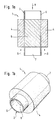
- Figs. 1A and 1B show a preferred embodiment of a heat exchanger basic module 1 which is part of the heat exchanger according to the invention described below.
- the basic heat exchanger module 1 has a tubular boundary wall 2 with a circular cross section.
- the tubular boundary wall 2 or the pipe section 2 is surrounded by a tubular outer packing 4 made of porous, flowable sintered metal, which also has a circular cross section.
- the pack 4 does not enclose the entire length of the tubular boundary wall 2.
- the interior of the pipe section 2 is filled with an inner pack 6 made of porous, flowable sintered metal. Again, not the entire length of the pipe section 2 but only part of it is filled with sintered metal.
- FIG. 1 shows a preferred embodiment of a heat exchanger basic module 1 which is part of the heat exchanger according to the invention described below.
- the basic heat exchanger module 1 has a tubular boundary wall 2 with a circular cross section.
- the tubular boundary wall 2 or the pipe section 2 is surrounded by a tub
- the length of the filling or the covering of the pipe section 2 by the outer or inner packing made of sintered metal is the same.
- the parts of the pipe section 2 that are not enveloped or filled by the packs 4 and 6 form connecting pieces 5 and 7.
- the boundary wall is sintered.
- the sintering of the packs 4 and 6 with the boundary wall or the pipe section 2 ensures an optimal heat transfer.
- the inside of the pipe section 2 forms an inner flow channel 8 for the heat-emitting or heat-absorbing side.
- the position of the outer packing 4 defines an outer flow channel 9.
- FIG. 2A and 2B show a first embodiment of a module receiving part of a heat exchanger according to the invention in a modular design.
- 2A shows one half of a module receiving part 10 from the inside and
- FIG. 2B shows the entire module receiving part 10 consisting of two parts according to FIG. 2A in a section along the line AA from FIG. 2A.
- the module receiving part 10 has a module holder 12, into which, for example, two heat exchanger basic modules 1 are releasably inserted, which are placed one behind the other with adjoining connecting pieces 5 and 7 in the module receiving part.
- the two basic modules are sealed or welded to one another in such a way that the interior of the tube pieces 2 together form a continuous flow channel.
- the various flow channels for the heat-absorbing or heat-absorbing medium can be seen from FIG. 2A.
- the connecting pieces 5 and 7 of the heat exchanger basic module 1 open into areas 14 and 15, into which the medium guided in the inner flow channel 8 is supplied or from which this medium is removed.
- the medium flowing through the outer packing 4 of sintered metal is supplied or discharged in annular regions 16 and 17.
- the two basic modules 1 are inserted into one half of the module receiving part 10 and the two parts or halves of the module receiving part 10 are assembled as shown in FIG. 2B and screwed together by means of screws 18.
- the two parts of the module receiving part 10 or the flow channels for the heat-absorbing or heat-dissipating medium are sealed by seals 19. Alternatively, the two parts can also be welded if there are special tightness requirements.
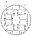
- FIG. 3A and 3B show a second and a third embodiment of a heat exchanger level according to the present invention.
- FIG. 3A shows, in an analogous representation to FIG. 2A, a half 20a of a module receiving part 20 for nine basic heat exchanger modules 1 arranged in the form of a spoke, only one basic heat exchanger module 1 being shown.
- 3B shows a perspective illustration of a disassembled heat exchanger plane with the two halves 20a and 20b of a module receiving part 20 in which eight heat exchanger basic modules 1 can be inserted into module holders 22 in the manner of the spokes of a wheel.
- the module receiving part 20 has an annular cylindrical shape with an inner cylinder wall 24 and an outer cylinder wall 25.
- the connectors 5 and 7 of the heat exchanger basic modules 1 pass through the inner cylinder wall 24 and the outer cylinder wall 25.
- the heat transport medium flowing in the inner flow channels 8 is supplied in the region of the inner cylinder wall 24 and flows via the connectors 5 into the inner flow channels 8
- the heat transfer medium flows out of the heat exchanger level again via the connection pieces 7.
- the heat transport medium flowing through the outer packing 4 of sintered metal is supplied or discharged in regions 26 and 27.
- 3A or 3B can be used particularly advantageously if a particularly good pressure balance between the individual modules is desired, since the flow paths of the individual basic heat exchanger modules are completely identical.
- the heat exchanger level can be inserted into a tubular or cylindrical pressure jacket 28.
- Fig. 4 shows a fourth embodiment of a heat exchanger level with a module receiving part 30 consisting of two halves 30a and 30b.
- four basic heat exchanger modules 1 are inserted into module holders 32 in the module receiving part 30.
- the axes of the inner flow channels 8 of the individual heat exchanger basic modules 1 lie in the module receiving part 30 with a circular cross section parallel to the sides of an inscribed square.
- the connecting pieces 5 of the heat exchanger basic modules 1 open into a region 33a of a first inlet duct and into a region 35a of a second inlet duct for the heat transport medium flowing in the inner flow duct 8.
- the connectors 7 of the heat exchanger basic modules 1 open out in a region 33b of a first outlet duct and in a region 35b of a second outlet duct.
- the heat transport medium flowing in the outer flow channel 9 is supplied in a region 36 or 37 and withdrawn from the collecting region 38 again from the heat exchanger or the heat exchanger level.
- the heat transfer medium is guided in counter-current in the heat exchanger basic modules 1.
- FIG. 5 shows a further embodiment of a half 40a of a module receiving part 40 of a heat exchanger level, which, like the heat exchanger level of FIG. 3B, offers space for eight basic heat exchanger modules 1.
- the outside diameter of the module receiving part 20 is smaller than the outside diameter of the module receiving part 20.
- the connecting pieces 5 of the heat exchanger basic modules 1 open into a region 42, via which the heat transport medium flowing in the inner flow channel 8 is supplied.
- the connecting pieces 7 of the heat exchanger basic modules 1 open into an area 44 or 45 from which the heat transport medium flowing in the inner flow channel 8 is withdrawn.
- the heat transport medium flowing in the outer flow channel 9 is supplied in a region 46 and withdrawn from regions 48 and 49, respectively.
- the basic heat exchanger module 50 has a tubular boundary wall 52.
- the tubular boundary wall 52 or the tube piece 52 is surrounded by a tubular outer packing 54 made of porous, flowable sintered metal, which is slightly conical in shape.
- the packing 54 does not enclose the entire length of the tubular boundary wall 52.
- the interior of the pipe section 52 is filled with an inner packing 56 made of porous, flowable sintered metal.
- the packs 54 and 56 are sintered with the boundary wall or the pipe section 52 in order to achieve an optimal heat transfer between the two packs 54 and To enable 56 of sintered metal over the boundary wall 52.
- the parts of the pipe section 52 which are not enveloped or filled by the packs 54 and 56 form connecting pieces 55 and 57.
- the interior of the pipe section 52 forms an inner flow channel 58 for the heat-emitting or heat-absorbing side.
- the position of the outer packing 54 defines an outer flow channel 59.
- the basic heat exchanger module 50 corresponds to the basic module 1.
- FIG. 7 shows a section through a further embodiment of a heat exchanger level consisting of a one-piece module receiving part 60 into which a conically shaped basic heat exchanger module 50 can be inserted.
- the heat transport media are conducted in countercurrent or cocurrent through the flow channels 58 and 59, respectively.
- Flow channels 62 are provided for this purpose.
- FIG. 8 schematically shows a further embodiment of a heat exchanger level with a module receiving part 70 consisting of two halves 70a and 70b, in which seven basic heat exchanger modules 50 are arranged vertically in module holders 72. That is, the axes of the inner flow channels are arranged perpendicular to the plane in which the two halves 70a and 70b of the module receptacle 70 are folded together.
- the heat transport medium flows through the outer flow channel of the heat exchanger basic modules 50 and is collected in the area 52 and can be fed to a separation mechanism, not shown.
- the heat transport medium flowing in the inner flow channel can also be passed through channels 74 and 75.
- circumferential flow channels are provided which correspond to the channels 62 in their function.
- a vertical section through the module holders 72 corresponds to the sectional illustration according to FIG. 7.
- the embodiment according to FIG. 8 is particularly suitable for cold evaporators. It could be empirically determined that an otherwise unchanged basic heat exchanger module 50 for cold evaporation of R12 for the cooling of compressed air yielded approximately 20% higher K values if, according to the embodiment of FIGS. 7A, 7B and 8 was arranged vertically with a steam guide from bottom to top and not horizontally. At the same time, the steam could be overheated up to 5 ° C without resulting in a measurable deterioration in the air outlet temperature.
Landscapes
- Engineering & Computer Science (AREA)
- Physics & Mathematics (AREA)
- Thermal Sciences (AREA)
- Mechanical Engineering (AREA)
- General Engineering & Computer Science (AREA)
- Chemical & Material Sciences (AREA)
- Dispersion Chemistry (AREA)
- Heat-Exchange Devices With Radiators And Conduit Assemblies (AREA)
- Physical Or Chemical Processes And Apparatus (AREA)
Abstract
Description
Die Erfindung betrifft einen Wärmetauscher in Modulbauweise gemäß den im Oberbegriff von Anspruch 1 angegebenen Merkmalen.The invention relates to a heat exchanger in modular design according to the features specified in the preamble of
Ein Wärmetauscher dieser Art ist durch die US-A-34 93 042 bekanntgeworden. Er besitzt wenigstens eine Wärmetauscherebene, die jeweils ein Modulaufnahmeteil mit einer Mehrzahl von darin eingebauten Wärmetauscher-Grundmodulen aufweist, wobei die einzelnen Wärmetauscher-Grundmodule jeweils eine Begrenzungswand aufweisen, durch die der Wärmeübergang von Wärme abgebender Seite des Wärmetauschers zu Wärme aufnehmender Seite des Wärmetauschers erfolgt, zumindest eine Seite der Begrenzungswand mit einer einen ersten Strömungskanal bildenden Packung aus porösem, durchströmbaren Sintermetall versehen ist und das Modulaufnahmeteil zusammen mit den Grundmodulen einen zweiten Strömungskanal für die Wärme abgebende und/oder Wärme aufnehmende Seite des Wärmetauschers festlegt. Trotz der somit verwirklichten Modulbauweise ist es bei dem bekannten Wärmetauscher dennoch nicht möglich, diesen nach seinem Zusammenbau entsprechend einem Baukastenprinzip zu variieren und abzuändern, bspw. um sich wandelnden Anspruchsprofilen bzw. Leistungsforderungen gerecht zu werden. Denn das setzte bei dem bekannten Wärmetauscher die Zerstörung des die Grundmodule aufnehmenden Wärmetauschergehäuses voraus.A heat exchanger of this type has become known from US-A-34 93 042. It has at least one heat exchanger level, each of which has a module receiving part with a plurality of heat exchanger basic modules installed therein, the individual heat exchanger basic modules each having a boundary wall through which the heat transfer takes place from the heat-emitting side of the heat exchanger to the heat-absorbing side of the heat exchanger, at least one side of the boundary wall is provided with a packing made of porous, flowable sintered metal and the module receiving part, together with the basic modules, defines a second flow channel for the heat-emitting and / or heat-absorbing side of the heat exchanger. Despite the modular construction thus implemented, it is nevertheless not possible in the known heat exchanger to vary and change it after its assembly in accordance with a modular principle, for example in order to meet changing demands or performance requirements. Because that required the destruction of the heat exchanger housing that accommodates the basic modules in the known heat exchanger.
Bei anderen pulvermetallurgisch gefertigten Wärmetauschern, d.h. Wärmetauschern mit Sintermetall, ist es bekannt, die Wärmeleitung bzw. die Wärmeübertragungsleistung zwischen einer Wärme aufnehmenden Seite und einer Wärme abgebenden Seite dadurch zu verbessern, daß durch Sintern oder sinterähnliche Prozesse erreichte durchströmbare porige Packungen die aktiven Wärmetauschflächen vergrößern. So ist bspw. aus der DE-GM 72 27 102 ein Wärmetauscher bekannt, bei dem ein rohrförmiger Strömungskanal mit Sintermetall verfüllt und der rohrförmige Strömungskanal mit einem schlauchförmigen Mantel aus Sintermetall umgeben ist, der wiederum von einem Gehäuse umschlossen wird. Ähnliche Konstruktionen sind aus der DE 14 42 601 A1, der DE-GM 80 01 502 sowie der DE 34 35 319 A1 bekannt. Bei der Konstruktion nach der DE 34 35 319 A1 ist zusätzlich noch das Sintermetall auf einer Seite des Wärmetauschers mit einer Katalysatorsubstanz überzogen, so daß katalytische Reaktoren vorliegen.In other powder-metallurgy heat exchangers, ie heat exchangers with sintered metal, it is known to improve the heat conduction or the heat transfer performance between a heat-absorbing side and a heat-emitting side in that porous packings which can be flowed through by sintering or sinter-like processes increase the active heat exchange surfaces. For example, from DE-GM 72 27 102 a heat exchanger is known in which a tubular Flow channel filled with sintered metal and the tubular flow channel is surrounded by a tubular jacket made of sintered metal, which in turn is enclosed by a housing. Similar constructions are known from DE 14 42 601 A1, DE-GM 80 01 502 and DE 34 35 319 A1. In the construction according to DE 34 35 319 A1, the sintered metal is additionally coated on one side of the heat exchanger with a catalyst substance, so that catalytic reactors are present.
Aufgrund der großen für den Wärmetausch aktiven inneren Oberfläche des Sintermetalls wiesen diese Wärmetauscher sehr hohe α -Werte bezogen auf die Fläche der die beiden Seiten der Wärmetauscher trennenden Rohrwandung auf. Nachteilig bei derartigen Wärmetauschern ist aber der vergleichsweise hohe Druckverlust in dem porösen Sintermetall bezogen auf die durchströmte Strecke.Because of the large inner surface of the sintered metal that is active for heat exchange, these heat exchangers had very high α values in relation to the area of the tube wall separating the two sides of the heat exchanger. A disadvantage of such heat exchangers, however, is the comparatively high pressure loss in the porous sintered metal in relation to the section through which the flow passes.
Um zu hohe Druckverluste zu vermeiden ist es aus der DE 19 02 229 A1 bekannt, anstelle des feinporigen Sintermetalls gröbere Strukturen mit wesentlich größeren Porendurchmessern, insbesondere Kugelmatrix-Anordnungen zu verwenden. Bei diesem bekannten Wäretauscher ist, zwar der Druckverlust geringer als bei den vorstehend beschriebenen, jedoch verschlechtert sich dadurch der α -Wert.In order to avoid excessive pressure losses, it is known from
Ein weiterer Nachteil aller vorstehend beschriebenen Strukturen besteht darin, daß jeder der bekannten Wärmetauscher für eine bestimmte Wärmetauscherleistung konzipiert sein muß. Darüberhinaus müssen die bekannten Bauteile ganz speziell auf eine bestimmte Funktion hin, z.B. Rekuperator, Verdampfer etc., ausgelegt sein. Die Herstellungskosten der bekannten Strukturen sind wegen hoher Ausschußraten vergleichsweise hoch, da beim Versintern vorkommende Formveränderungen das gesamte Bauteil unbrauchbar machen können.Another disadvantage of all the structures described above is that each of the known heat exchangers must be designed for a specific heat exchanger output. In addition, the known components have to be specific to a specific function, e.g. Recuperator, evaporator, etc., be designed. The manufacturing costs of the known structures are comparatively high because of high reject rates, since changes in shape occurring during sintering can render the entire component unusable.
Der Erfindung liegt die Aufgabe zugrunde, einen Wärmetauscher mit Sintermetall zu schaffen, der für unterschiedliche Anwendungszwecke und Funktionen preiswert herzustellen ist.The invention has for its object to provide a heat exchanger with sintered metal for different Applications and functions is inexpensive to manufacture.
Diese Aufgabe wird mit den im kennzeichnenden Teil von Anspruch 1 enthaltenen Merkmalen gelöst. Vor allem dadurch, daß das über Zu- bzw. Abströmbereiche an die Strömungskanäle des Wärmetauscher-Grundmoduls angeschlossene Aufnahmeteil zweiteilig, mit gegeneinander abgedichteten halbschalenartigen Gehäuseteilen ausgebildet ist, die sich jederzeit lösen lassen, ergibt sich auf einfache Weise die Möglichkeit, die Module aus den Aufnahmestellen zu entfernen, ohne daß dies eine Zerstörung der Module und/oder des Modulaufnahmeteils bzw. des Wärmetauschergehäuses zur Folge hat. Da sich mehrere Wärmetauscher-Grundmodule mit Sintermetall lösbar in ein Modulaufnahmeteil einsetzen lassen, können auf einfache Art und Weise Wärmetauscher mit unterschiedlichen Leistungsstufen realisiert werden. In ein und dasselbe Modulaufnahmeteil lassen sich eine Mehrzahl von Wärmetauscher-Grundmodulen lösbar einsetzen, d.h. die Wärmetauscher-Grundmodule lassen sich auch nachträglich wieder aus dem bzw. den Modulaufnahmeteilen entfernen, ohne daß dies eine Zerstörung der Module zur Folge hätte. Durch die Lösbarkeit der Wärmetauscher-Grundmodule in den Modulaufnahmeteilen ist gewährleiset, daß ein erfindungsgemäßer Wärmetauscher in Modulbauweise nachträglich an unterschiedliche Funktionen und/oder Leistungen angepaßt werden kann. Durch das Einsetzen einer unterschiedlichen Zahl von Wärmetauscher-Grundmodulen in ein Modulaufnahmeteil lassen sich Wärmetauscherebenen mit unterschiedlichen Wärmeleistungen realisieren. Durch die Kombination von mehreren Wärmetauscherebenen mit ein und demselben Wärmetauscher-Grundmodul läßt sich die Leistungsbandbreite beliebig erhöhen. Die miteinander zu einem Wärmetauscher kombinierten Wärmetauscherebenen können sich hinsichtlich Leistung, Funktion und Baugröße voneinander unterscheiden.This object is achieved with the features contained in the characterizing part of
Ein besonderer Vorteil besteht darin, daß die Herstellungskosten des erfindungsgemäßen Wärmetauschers wesentlich unter der Herstellungskosten vergleichbarer konventioneller Wärmetauscher liegen. Dies ist auf die Verwendung von standardisierten Bauteilen - Wärmetauscher-Grundmodul und Modulaufnahmeteil - zurückzuführen. Zusätzlich führen bei der Versinterung auftretende Verformungen nicht dazu, daß der gesamte Wärmetauscher Ausschuß ist, sondern lediglich das jeweilige Grundmodul. Die hinsichtlich ihrer Baugröße vergleichsweise kleinen Wärmetauscher-Grundmodule sind fertigungstechnisch leichter beherrschbar als großvolumige Teile, d. h. die Ausschußrate ist kleiner.A particular advantage is that the manufacturing costs of the heat exchanger according to the invention are significantly lower than the manufacturing costs of comparable conventional heat exchangers. This is due to the use of standardized components - the heat exchanger basic module and module receiving part. In addition, deformations occurring during sintering do not mean that the entire heat exchanger is rejected, but only the respective basic module. The heat exchanger base modules, which are comparatively small in terms of their size, are easier to control in terms of production technology than large-volume parts, i. H. the reject rate is lower.
Ausgehend von jeweils vergleichbaren Wärmetauscherleistungen gelingt es mit dem erfindungsgemäßen Wärmetauscher die Herstellungskosten um mindestens 30 % zu senken. Insbesondere bei druckbelasteten Wärmetauschern mit höheren Leistungen können noch höhere Einsparungspotentiale realisiert werden, da sich die kompakte Bauform auf die Größe der druckbelasteten Mantelrohre und Druckdeckel kostengünstig auswirkt.On the basis of comparable heat exchanger performances, the heat exchanger according to the invention succeeds in reducing the production costs by at least 30%. In particular with heat exchangers under pressure with higher outputs, even greater savings potential can be realized, since the compact design has a cost-effective effect on the size of the pressure-stressed jacket pipes and pressure covers.
Durch die Aufteilung des Massenstroms in viele Teile und deren wärmetechnische Behandlung in den "kurzen" Wärmetauscher-Grundmodulen können die hervorragenden wärmetechnischen Eigenschaften eines versinterten Rohres genutzt werden, ohne daß hierfür vergleichsweise hohe Druckverluste in Kauf genommen werden müssen. Durch den Aufbau eines bestimmten Wärmetauschers aus einer Mehrzahl von Wärmetauscher-Grundmodulen ist es möglich, die bei Wärmetauscher mit Sintermetall auftretenden hohen Druckverluste zu minimieren, da in den Wärmetauscher-Grundmodulen sehr kurze Durchströmstrecken realisiert werden können. Durch parallele Anströmung der Mehrzahl von Wärmetauscher-Grundmodulen lassen sich Druckverluste erreichen, wie sie bei herkömmlichen konventionellen Wärmetauschern, wie z.B. Rohrbündel- oder Plattenwärmetauschern, üblich sind.By splitting the mass flow into many parts and treating them in the "short" heat exchanger basic modules, the excellent thermal properties of a sintered pipe can be used, without having to put up with comparatively high pressure losses. By constructing a specific heat exchanger from a plurality of basic heat exchanger modules, it is possible to minimize the high pressure losses which occur in heat exchangers with sintered metal, since very short flow paths can be achieved in the basic heat exchanger modules. By parallel flow to the plurality of basic heat exchanger modules, pressure losses can be achieved, as are customary in conventional conventional heat exchangers, such as, for example, tube bundle or plate heat exchangers.
Gemäß der besonders bevorzugten Ausführungsform nach Anspruch 2 besteht das Wärmetauscher-Grundmodul aus einem kurzen Rohrstück, das die Begrenzungswand zwischen der Wärme aufnehmenden und der Wärme abgebenden Seite eines Wärmetauschers bildet. Dies führt einerseits zu einer sehr kompakten Bauform und ist andererseits fertigungstechnisch bzw. sinterungstechnisch gut zu handhaben.According to the particularly preferred embodiment according to claim 2, the basic heat exchanger module consists of a short piece of pipe which forms the boundary wall between the heat-absorbing and the heat-emitting side of a heat exchanger. On the one hand, this leads to a very compact design and, on the other hand, it is easy to handle in terms of production technology or sintering technology.
Gemäß der bevorzugten Ausgestaltung nach Anspruch 3 ist das Rohrinnere und/oder die Außenseite des Rohrstücks mit einer Packung aus porösem, durchströmbaren Sintermetall versehen. Diese Wärmetauscher-Grundmodule in Form von kurzen Rohrstücken mit Sintermetallfüllung und/oder Sintermetallmantel sind vergleichsweise einfach und preiswert herzustellen.According to the preferred embodiment according to claim 3, the tube interior and / or the outside of the tube piece is provided with a packing made of porous, flowable sintered metal. These basic heat exchanger modules in the form of short pipe sections with sintered metal filling and / or sintered metal jacket are comparatively simple and inexpensive to manufacture.
Durch Beschichtung einer Sinterpackung mit einer Katalysatorsubstanz (Anspruch 10) lassen sich katalytische Reaktoren für unterschiedliche Zwecke und mit unterschiedlichen Leistungscharakteristika realisieren.By coating a sintered packing with a catalyst substance, catalytic reactors can be realized for different purposes and with different performance characteristics.
Die weiteren Unteransprüche beziehen sich auf vorteilhafte Ausgestaltungen der Erfindung.The further subclaims relate to advantageous refinements of the invention.
Einzelheiten und Vorteile der vorliegenden Erfindung ergeben sich aus der nachfolgenden Beschreibung unter Bezugnahme auf die Zeichnung.Details and advantages of the present invention will become apparent from the following description with reference to the drawing.
Es zeigt:
- Fig. 1A
- einen Schnitt durch eine erste Ausführungsform eines Wärmetauscher-Grundmoduls,
- Fig. 1B
- eine perspektivische Darstellung des Wärmetauscher-Grundmoduls von Fig. 1A,
- Fig. 2A
- eine Ansicht der Innenseite eines Teiles eines zweiteiligen Modul-Aufnahmeteils,
- Fig. 2B
- einen Schnitt durch das in Fig. 2A dargestellte Teil entlang der Linie A-A,
- Fig. 3A
- eine analoge Ansicht zu Fig. 2A einer zweiten Ausführungsform der vorliegenden Erfindung,
- Fig. 3B
- eine perspektivische Darstellung einer Ausführungsform einer Wärmetauscherebene,
- Fig. 4
- in analoger Darstellung zu Fig. 2A eine dritte Ausführungsform,
- Fig. 5
- in analoger Darstellung zu Fig. 2A eine vierte Ausführungsform,
- Fig. 6
- eine zweite Ausführungsform eines Wärmetauscher-Grundmoduls,
- Fig. 7
- eine Schnittdarstellung einer weiteren Ausführungsform eines Modulaufnahmeteils, und
- Fig. 8
- in analoger Darstellung zu Fig. 2A eine weitere Ausführungsform einer Hälfte eines Modulaufnahmeteils.
- Fig. 1A
- 2 shows a section through a first embodiment of a basic heat exchanger module,
- Figure 1B
- 1 shows a perspective illustration of the heat exchanger basic module from FIG. 1A,
- Figure 2A
- a view of the inside of a part of a two-part module receiving part,
- Figure 2B
- 3 shows a section through the part shown in FIG. 2A along the line AA,
- Figure 3A
- 2 shows a view analogous to FIG. 2A of a second embodiment of the present invention,
- Figure 3B
- 2 shows a perspective illustration of an embodiment of a heat exchanger level,
- Fig. 4
- in a representation analogous to FIG. 2A, a third embodiment,
- Fig. 5
- in a representation analogous to FIG. 2A, a fourth embodiment,
- Fig. 6
- a second embodiment of a heat exchanger basic module,
- Fig. 7
- a sectional view of another embodiment of a module receiving part, and
- Fig. 8
- in a representation analogous to FIG. 2A, a further embodiment of one half of a module receiving part.
Figs. 1A und 1B zeigen eine bevorzugte Ausführungsform eines Wärmetauscher-Grundmoduls 1, das Teil der nachfolgend beschriebener erfindungsgemäßer Wärmetauscher ist. Das Wärmetauscher-Grundmodul 1 weist eine rohrförmige Begrenzungswand 2 mit kreisförmigem Querschnitt auf. Die rohrförmige Begrenzungswand 2 bzw. das Rohrstück 2 ist von einer schlauchförmigen äußeren Packung 4 aus porösem, durchströmbaren Sintermetall umgeben, das ebenfalls einen kreisförmigen Querschnitt aufweist. Die Packung 4 umschließt dabei nicht die gesamte Länge der rohrförmigen Begrenzungswand 2. Das Innere des Rohrstücks 2 ist mit einer inneren Packung 6 aus porösem, durchströmbaren Sintermetall ausgefüllt. Wiederum ist nicht die gesamte Länge des Rohrstücks 2 sondern nur ein Teil davon mit Sintermetall ausgefüllt. In der in Fig. 1 gezeigten Ausführungsform sind die Länge der Ausfüllung bzw. der Umhüllung des Rohrstücks 2 durch die äußere bzw. innere Packung aus Sintermetall gleich. Die von den Packungen 4 bzw. 6 nicht umhüllten bzw. ausgefüllten Teile des Rohrstückes 2 bilden Anschlußstücke 5 bzw. 7. Vorzugsweise ist sowohl in dem Rohrstück 2 als auch außen eine Packung 4 bzw. 6 aus Sintermetall vorgesehen, die mit dem Rohrstück bzw. der Begrenzungswand versintert ist. Durch die Versinterung der Packungen 4 bzw. 6 mit der Begrenzungswand bzw. dem Rohrstück 2 wird ein optimaler Wärmeübergang gewährleistet. Das Innere des Rohrstücks 2 bildet einen inneren Strömungskanal 8 für die Wärme abgebende bzw. Wärme aufnehmende Seite. Die Lage der äußerne Packung 4 definiert einen äußeren Strömungskanal 9.Figs. 1A and 1B show a preferred embodiment of a heat exchanger
Fig. 2A und 2B zeigen eine erste Ausführungsform eines Modulaufnahmeteils eines erfindungsgemäßen Wärmetauschers in Modulbauweise. Fig. 2A zeigt eine Hälfte eines Modulaufnahmeteils 10 von innen und Fig. 2B zeigt das gesamte aus zwei Teilen gemäß Fig. 2A bestehende Modulaufnahmeteil 10 im Schnitt entlang der Linie A-A von Fig. 2A. Das Modulaufnahmeteil 10 weist eine Modulhalterung 12 auf, in die beispielsweise zwei Wärmetauscher-Grundmodule 1 lösbar eingesetzt werden, die hintereinanderliegend mit aneinanderliegenden Anschlußstücken 5 bzw. 7 in das Modulaufnahmeteil eingelegt werden. Die beiden Grundmodule sind so gegeneinander abgedichtet bzw. verschweißt, daß das Innere der Rohrstücke 2 zusammen einen durchgehenden Strömungskanal bilden. Aus Fig. 2A sind die verschiedenen Strömungskanäle für das Wärme aufnehmende bzw. Wärme abnehmende Medium zu erkennen. Die Anschlußstücke 5 bzw. 7 des Wärmetauscher-Grundmoduls 1 münden in Bereiche 14 bzw. 15, in die das im inneren Strömungskanal 8 geführte Medium zugeführt wird bzw. aus dem dieses Medium abgeführt wird. In ringförmigen Bereichen 16 bzw. 17 wird das die äußere Packung 4 aus Sintermetall durchströmende Medium zu- bzw. abgeführt. Die zwei Grundmodule 1 werden in eine Hälfte des Modulaufnahmeteils 10 eingelegt und die beiden Teile bzw. Hälften des Modulaufnahmeteils 10 werden wie aus Fig. 2B ersichtlich zusammengesetzt und mittels Schrauben 18 verschraubt. Die zwei Teile des Modulaufnahmeteiles 10 bzw. die Strömungskanäle für das Wärme aufnehmende bzw. Wärme abgebende Medium werden durch Dichtungen 19 abgedichtet. Alternativ können bei besonderen Anforderungen hinsichtlich Dichtheit die beiden Teile auch verschweißt werden.2A and 2B show a first embodiment of a module receiving part of a heat exchanger according to the invention in a modular design. 2A shows one half of a
Fig. 3A und 3B zeigen eine zweite und eine dritte Ausführungsform einer Wärmetauscherebene gemäß der vorliegenden Erfindung. Fig. 3A zeigt in analoger Darstellung zu Fig. 2A eine Hälfte 20a eines Modulaufnahmeteils 20 für neun speichenförmig angeordneten Wärmetauscher-Grundmodulen 1, wobei lediglich ein Wärmetauscher-Grundmodul 1 eingezeichnet ist. Fig. 3B zeigt eine perspektivische Darstellung einer auseinandergenommenen Wärmetauscherebene mit den zwei Hälften 20a und 20b eines Modulaufnahmeteils 20 in der sich acht Wärmetauscher-Grundmodule 1 nach Art der Speichen eines Rades in Modulhalterungen 22 einlegen lassen. Das Modulaufnahmeteil 20 weist in zusammengesetztem Zustand eine ringzylindrische Form mit einer inneren Zylinderwand 24 und einer äußeren Zylinderwand 25 auf. Die Anschlußstücke 5 bzw. 7 der Wärmetauscher-Grundmodule 1 durchsetzen die innere Zylinderwand 24 bzw. die äußere Zylinderwand 25. Das in den inneren Strömungskanälen 8 strömende Wärmetransportmedium wird im Bereich der inneren Zylinderwand 24 zugeführt und strömt über die Anschlußstücke 5 in die inneren Strömungskanäle 8. Über die Anschlußstücke 7 strömt das Wärmetransportmedium aus der Wärmetauscherebene wieder heraus. Das die äußere Packung 4 aus Sintermetall durchströmende Wärmetransportmedium wird in Bereichen 26 bzw. 27 zugeführt bzw. abgeführt. Die Ausführungsformen der Wärmetauscherebenen gemäß Fig. 3A bzw. 3B sind besonders vorteilhaft einzusetzen, wenn ein besonders guter Druckabgleich zwischen den einzelnen Modulen gewünscht wird, da die Anströmstrecken der einzelnen Wärmetauscher-Grundmodule völlig identisch sind. Wie in Fig. 3A angedeutet läßt sich die Wärmetauscherebene in einen rohrförmigen bzw. zylindrischen Druckmantel 28 einsetzen.3A and 3B show a second and a third embodiment of a heat exchanger level according to the present invention. FIG. 3A shows, in an analogous representation to FIG. 2A, a
Fig. 4 zeigt eine eine vierte Ausführungsform einer Wärmetauscherebene mit einem Modulaufnahmeteil 30 bestehend aus zwei Hälften 30a und 30b. Bei dieser Wärmetauscherebene sind in das Modulaufnahmeteil 30 vier Wärmetauscher-Grundmodule 1 in Modulhalterungen 32 eingesetzt. Die Achsen der inneren Strömungskanäle 8 der einzelnen Wärmetauscher-Grundmodule 1 liegen in dem Modulaufnahmeteil 30 mit kreisförmigem Querschnitt parallel zu den Seiten eines einbeschriebenen Quadrats. Die Anschlußstücke 5 der Wärmetauscher-Grundmodule 1 münden in einen Bereich 33a eines ersten Einlaßkanales und in einen Bereich 35a eines zweiten Einlaßkanales für das im inneren Strömungskanal 8 strömenden Wärmetransportmedium. Die Anschlußstücke 7 der Wärmetauscher-Grundmodule 1 münden in einen Bereich 33b eines ersten Auslaßkanales und in einen Bereich 35b eines zweiten Auslaßkanales. Das in dem äußeren Strömungskanal 9 strömende Wärmetransportmedium wird in einem Bereich 36 bzw. 37 zugeführt und aus einem Sammelbereich 38 wieder dem Wärmetauscher bzw. der Wärmetauscherebene entzogen. Das Wärmetransportmedium wird dabei in den Wärmetauscher-Grundmodulen 1 im Gegenstrom geführt.Fig. 4 shows a fourth embodiment of a heat exchanger level with a
Fig. 5 zeigt eine weitere Ausführungsform einer Hälfte 40a eines Modulaufnahmeteils 40 einer Wärmetauscherebene, die wie die Wärmetauscherebene von Fig. 3B Platz für acht Wärmetauscher-Grundmodule 1 bietet. Der Außendurchmesser des Modulaufnahmeteils 20 ist jedoch dabei kleiner als der Außendurchmesser des Modulaufnahmeteils 20. Die Anschlußstücke 5 der Wärmetauscher-Grundmodule 1 münden in einen Bereich 42, über den das im inneren Strömungskanal 8 fließende Wärmetransportmedium zugeführt wird. Die Anschlußstücke 7 der Wärmetauscher-Grundmodule 1 münden in einem Bereich 44 bzw. 45 aus denen das im inneren Strömungskanal 8 strömende Wärmetransportmedium abgezogen wird. Das im äußeren Strömungskanal 9 strömende Wärmetransportmedium wird in einem Bereich 46 zugeführt und aus Bereichen 48 bzw. 49 abgezogen.FIG. 5 shows a further embodiment of a half 40a of a
Fig. 6 zeigt einen Schnitt durch ein Wärmetauscher-Grundmodul 50 gemäß einer zweiten Ausführungsform. Das Wärmetauscher-Grundmodul 50 weist eine rohrförmige Begrenzungswand 52 auf. Die rohrförmige Begrenzungswand 52 bzw. das Rohrstück 52 ist von einer schlauchförmigen äußeren Packung 54 aus porösem, durchströmbaren Sintermetall umgeben, die leicht konisch geformt ist. Die Packung 54 umschließt dabei nicht die gesamte Länge der rohrförmigen Begrenzungswand 52. Das Innere des Rohrstücks 52 ist mit einer inneren Packung 56 aus porösem, durchströmbaren Sintermetall ausgefüllt. Die Packungen 54 und 56 sind mit der Begrenzungswand bzw. dem Rohrstück 52 versintert, um wie bei dem Grundmodul 1 einen optimalen Wärmeübergang zwischen den beiden Packungen 54 und 56 aus prösem Sintermetall über die Begrenzungswand 52 zu ermöglichen. Die von den Packungen 54 bzw. 56 nicht umhüllten bzw. ausgefüllten Teile des Rohrstückes 52 bilden Anschlußstücke 55 bzw. 57. Das Innere des Rohrstücks 52 bildet einen inneren Strömungskanal 58 für die Wärme abgebende bzw. Wärme aufnehmende Seite. Die Lage der äußeren Packung 54 definiert einen äußeren Strömungskanal 59. Abgesehen von der konisch geformten äußeren Sinterpackung 54 stimmt das Wärmetauscher-Grundmodul 50 mit dem Grundmodul 1 überein.6 shows a section through a heat exchanger
Fig. 7 zeigt einen Schnitt durch eine weitere Ausführungsform einer Wärmetauscherebene bestehend aus einem einteiligen Modulaufnahmeteil 60 in das ein konisch geformtes Wärmetauscher-Grundmodul 50 eingesetzt werden kann. Die Wärmetransportmedien werden im Gegenstrom oder im Gleichstrom durch die Strömungskanälen 58 bzw. 59 geführt.FIG. 7 shows a section through a further embodiment of a heat exchanger level consisting of a one-piece
Werden mehrere unterschiedliche Wärmetauscherebenen mit unterschiedlichen Funktionen miteinander verbunden, kann es unter Umständen notwendig sein, ein oder mehrere Ebenen blind zu schalten. Zu diesem.Zweck sind Strömungskanäle 62 vorgesehen.If several different heat exchanger levels with different functions are connected to each other, it may be necessary to blind one or more levels.
Fig. 8 zeigt schematisch eine weitere Ausführungsform einer Wärmetauscherebene mit einem aus zwei Hälften 70a und 70b bestehenden Modulaufnahmeteil 70, bei der sieben Wärmetauscher-Grundmodule 50 senkrecht in Modulhalterungen 72 angeordnet sind. D. h. die Achsen der inneren Strömungskanäle sind senkrecht zu der Ebene angeordnet, in der die beiden Hälften 70a und 70b der Modulaufnahme 70 zusammengeklappt werden. Das Wärmetransportmedium durchströmt den äußeren Strömungskanal der Wärmetauscher-Grundmodule 50 und wird im Bereich 52 gesammelt und können einem nicht dargestellten Abscheidemechanismus zugeführt werden. Das im inneren Strömungskanal strömende Wärmetransportmedium kann auch durch Kanäle 74 und 75 geführt werden. Im Randbereich des Modulaufnahmeteils 70 sind umlaufenden Strömungskanäle vorgesehen, die in ihrer Funktion den Kanälen 62 entsprechen. Ein senkrechter Schnitt durch die Modulhalterungen 72 entspricht der Schnittdarstellung gemäß Fig. 7.8 schematically shows a further embodiment of a heat exchanger level with a
Die Ausführungsformen gemäß Fig. 8 ist besonders für Kaltverdampfer geeignet. Es konnte empirisch ermittelt werden, daß ein ansonsten unverändertes Wärmetausscher-Grundmodul 50 zur Kaltverdampfung von R12 für die Kühlung von Druckluft etwa 20 % höhere K-Werte erbrachte, wenn es gemäß der Ausführungsform von Figs. 7A, 7B und 8 senkrecht mit einer Dampfführung von unten nach oben angeordnet wurde und nicht waagrecht. Gleichzeitig konnte der Dampf hierbei bis zu 5°C überhitzt werden, ohne daß hieraus eine meßbare Verschlechterung der Luftaustrittstemperatur resultierte.The embodiment according to FIG. 8 is particularly suitable for cold evaporators. It could be empirically determined that an otherwise unchanged basic
Mit den vorstehend beschriebenen Wärmetauschern gelang es beispielsweise, Module zur Drucklufttrocknung zu konzipieren, die im Rekuperationsteil bei einer Durchströmlänge von 65 mm eine Temperaturabsenkung von 18,5°C bei einer Eintrittstemperatur von 35°C bewältigen und im Kaltverdampfer eine Verdampfungstemperatur von 0°C bei einer Durchströmstrecke von lediglich 45 mm zeigten. Bei gleichen Randparametern beträgt die abgewickelte Länge eines Koaxialwärmetauschers (Rekuperator + Kaltverdampfer) ca. 6 m. Beide Wärmetauscher erfüllen das Kriterium, eine Gesamtdruckdifferenz von ca. 160 mbar nicht zu überschreiten.With the heat exchangers described above, it was possible, for example, to design modules for drying compressed air which, in the recuperation section with a flow length of 65 mm, manage a temperature drop of 18.5 ° C at an inlet temperature of 35 ° C and an evaporation temperature of 0 ° C in the cold evaporator showed a flow path of only 45 mm. With the same boundary parameters, the developed length of a coaxial heat exchanger (recuperator + cold evaporator) is approx. 6 m. Both heat exchangers meet the criterion of not exceeding a total pressure difference of approx. 160 mbar.
Aus diesem Beispiel kann abgeleitet werden, daß die Durchströmstrecken von Wärmetauschern in Modulbausweise gemäß der vorliegenden Erfindung mit Sintermetall größenordnungsgemäß bei 2 % konventioneller Systeme liegen. Die K-Werte können unabhängig von Stoff und Phase um den Faktor 10 verbessert werden, so daß größenordnungsmäßig etwa 10 % der Rohrwandfläche eines konventionellen Wärmetauschers benötigt werden.From this example it can be deduced that the flow paths of heat exchangers in modular construction according to the present invention with sintered metal are of the order of magnitude at 2% of conventional systems. The K values can be improved by a factor of 10 regardless of substance and phase, so that about 10% of the pipe wall area of a conventional heat exchanger is required.
Claims (12)
- Heat exchanger of modular design comprising one or more heat exchanger planes each provided with a module receiving means (10; 20; 30; 40; 60) with heat exchanger base modules (1; 50) mounted therein, said heat exchanger base modules (1; 50) including a partition wall (2; 52) through which the heat transfer from the heat emitting side of the heat exchanger to the heat absorbing side of the heat exchanger takes place, there being provided on at least one side of said partition wall (2; 52) a packing (4,6; 54, 56) made of porous, permeable sintered metal which defines a first flow channel (9), while said module receiving means (10; 20; 30; 40; 60), together with said base modules (1; 50), defines a second flow channel (8) for the heat emitting and/or heat absorbing side of the heat exchanger, characterized in that the module receiving means (10, 20, 30, 40, 60) is in two parts and encloses the heat exchanger base modules in the manner of two half shells which are sealed off against each other and comprise inflow and outflow areas (14,15 and 16,17, respectively) for the fluid carried in said first and second flow channel (8 and 9, respectively), with connecting pieces (5,7) of the heat exchanger base modules (1; 50) terminating in said areas.
- Heat exchanger of modular design as set forth in claim 1, characterized in that the partition wall (2; 52) of the heat exchanger base module defines a tubular flow channel, and specifically one of circular cross-section, for the heat emitting or heat absorbing side.
- Heat exchanger of modular design as set forth in claim 2, characterized in that the packing (4, 6; 54, 56) of porous, permeable sintered metal encloses a portion of the longitudinal extension of the tubular flow channel in a tubelike manner and/or completely fills up the interior cross-section of the tubular flow channel over a portion of its longitudinal extension.
- Heat exchanger of modular design as set forth in any of claims 2 and 3, characterized in that the individual heat exchanger base modules are arranged vertically alongside each other in the module receiving means (10; 20; 30; 40; 60) in the manner of a shell-and-tube heat exchanger.
- Heat exchanger of modular design as set forth in claim 4, characterized in that the base modules are concave in shape.
- Heat exchanger of modular design as set forth in any of claims 2 and 3, characterized in that the individual base modules are arranged horizontally in one plane alongside each other in the module receiving means (10; 20; 30; 40; 60).
- Heat exchanger of modular design as set forth in claim 6, characterized in that the base modules are arranged like the spokes of a wheel in the module receiving means (10; 20; 30; 40; 60).
- Heat exchanger of modular design as set forth in any of the preceding claims, characterized in that the partition wall (2; 52) is made of aluminium and the sintered metal packing or packings (4, 6; 54, 56) is/are are made of porous sintered aluminium powder or granules.
- Heat exchanger of modular design as set forth in any of the preceding claims, characterized in that the module receiving means (10; 20; 30; 40; 60) is of circular cross-section.
- Heat exchanger of modular design as set forth in any of the preceding claims, characterized in that the sintered metal packings are coated with a catalyst material.
- Heat exchanger of modular design as set forth in any of the preceding claims, characterized in that the individual heat exchanger planes differ in terms of their structure and performance characteristics.
- Heat exchanger of modular design as set forth in any of the preceding claims, characterized in that the individual heat exchanger planes are arranged inside a common pressurized shell.
Applications Claiming Priority (3)
| Application Number | Priority Date | Filing Date | Title |
|---|---|---|---|
| DE3939674A DE3939674C2 (en) | 1989-11-30 | 1989-11-30 | Modular heat exchanger |
| DE3939674 | 1989-11-30 | ||
| PCT/DE1990/000930 WO1991008432A1 (en) | 1989-11-30 | 1990-11-30 | Heat exchanger using sintered metal |
Publications (2)
| Publication Number | Publication Date |
|---|---|
| EP0524926A1 EP0524926A1 (en) | 1993-02-03 |
| EP0524926B1 true EP0524926B1 (en) | 1995-01-11 |
Family
ID=6394539
Family Applications (1)
| Application Number | Title | Priority Date | Filing Date |
|---|---|---|---|
| EP90917118A Expired - Lifetime EP0524926B1 (en) | 1989-11-30 | 1990-11-30 | Heat exchanger using sintered metal |
Country Status (4)
| Country | Link |
|---|---|
| EP (1) | EP0524926B1 (en) |
| AT (1) | ATE117070T1 (en) |
| DE (2) | DE3939674C2 (en) |
| WO (1) | WO1991008432A1 (en) |
Families Citing this family (5)
| Publication number | Priority date | Publication date | Assignee | Title |
|---|---|---|---|---|
| JP2682361B2 (en) * | 1992-12-09 | 1997-11-26 | 日本鋼管株式会社 | Exhaust heat recovery type combustion device |
| JP2682362B2 (en) * | 1992-12-09 | 1997-11-26 | 日本鋼管株式会社 | Exhaust heat recovery type combustion device |
| IL108860A (en) * | 1994-03-04 | 1998-10-30 | Elisra Gan Ltd | Heat radiating element |
| DE102004010383B4 (en) * | 2004-03-03 | 2007-04-12 | Man Dwe Gmbh | Apparatus for simulating the reaction process in and method of optimizing tubular jacketed reactors |
| DE102012014813B9 (en) | 2012-07-26 | 2016-06-16 | Wieland-Werke Ag | Structured heatsinks in modular design |
Family Cites Families (8)
| Publication number | Priority date | Publication date | Assignee | Title |
|---|---|---|---|---|
| DE7227102U (en) * | 1972-12-21 | Sintermetallwerk Krebsoege Gmbh | Sintered metal filter | |
| FR1300303A (en) * | 1961-06-22 | 1962-08-03 | Centre Nat Rech Scient | Improvements to heat exchangers |
| US3339260A (en) * | 1964-11-25 | 1967-09-05 | Olin Mathieson | Method of producing heat exchangers |
| US3493042A (en) * | 1967-04-11 | 1970-02-03 | Olin Mathieson | Modular units and use thereof in heat exchangers |
| GB1250114A (en) * | 1969-02-18 | 1971-10-20 | ||
| GB1452290A (en) * | 1973-10-24 | 1976-10-13 | Advanced Materials Eng | Rotor for rotary regenerative heat exchanger |
| DE8001502U1 (en) * | 1980-01-22 | 1981-07-08 | Meineke, Ferdinand, Dipl.-Ing., 5608 Radevormwald | Heat exchangers, in particular for solar absorbers or supply air heating systems using exhaust air |
| DE3435319A1 (en) * | 1984-09-26 | 1986-04-03 | Michael 4150 Krefeld Laumen | CATALYTIC STEAM GENERATOR |
-
1989
- 1989-11-30 DE DE3939674A patent/DE3939674C2/en not_active Expired - Fee Related
-
1990
- 1990-11-30 DE DE59008270T patent/DE59008270D1/en not_active Expired - Fee Related
- 1990-11-30 WO PCT/DE1990/000930 patent/WO1991008432A1/en active IP Right Grant
- 1990-11-30 EP EP90917118A patent/EP0524926B1/en not_active Expired - Lifetime
- 1990-11-30 AT AT90917118T patent/ATE117070T1/en not_active IP Right Cessation
Also Published As
| Publication number | Publication date |
|---|---|
| DE3939674C2 (en) | 1995-06-08 |
| DE3939674A1 (en) | 1991-06-06 |
| DE59008270D1 (en) | 1995-02-23 |
| EP0524926A1 (en) | 1993-02-03 |
| ATE117070T1 (en) | 1995-01-15 |
| WO1991008432A1 (en) | 1991-06-13 |
Similar Documents
| Publication | Publication Date | Title |
|---|---|---|
| DE60310876T2 (en) | DIPPED EVAPORATOR WITH INTEGRATED HEAT EXCHANGER | |
| EP3585509B1 (en) | Heat exchanger and reactor | |
| DE2452734B2 (en) | Heating cylinder | |
| CH657207A5 (en) | REGENERATOR WITH A CIRCULATING, REGENERATIVE HEAT EXCHANGER. | |
| WO2016131786A1 (en) | Shell and tube heat exchanger | |
| DE2722288A1 (en) | PLATE-SHAPED EVAPORATOR | |
| EP0524926B1 (en) | Heat exchanger using sintered metal | |
| DE3536316A1 (en) | Laminated oil cooler | |
| EP0305706A2 (en) | Rotary drum | |
| DE2814326A1 (en) | POROESE SUPPORT FOR USE IN A DIVIDER WITH HOLLOW FIBER | |
| WO1992000129A1 (en) | Column body to take plate-type heat exchangers | |
| DE2524080C3 (en) | Heat exchanger in which a vaporous medium condenses while giving off heat to another medium | |
| DE3042557C2 (en) | Heat exchangers, in particular for solar power plants | |
| DE2805817A1 (en) | RECUPERATIVE HEAT EXCHANGER MADE OF CERAMIC MATERIAL | |
| DE19650086C1 (en) | Heat transmitter for gas-fluid heat exchange | |
| DE2414295C2 (en) | Heat exchanger for the condensation of steam | |
| DE102016103719B4 (en) | Fluid guidance device | |
| EP0394758B1 (en) | Heat exchanger | |
| EP0130404A2 (en) | Multi-stage heat exchanger | |
| EP3822569B1 (en) | Heat exchanger | |
| CH641893A5 (en) | Heat exchanger element, method for producing it, and a heat exchanger | |
| DE2121473A1 (en) | Tubular heat exchanger | |
| EP0230982B1 (en) | Cylindrical heat exchanger manufactured from prefabricated components, in particular a chimney recuperator | |
| DE1601167C3 (en) | Mixed heat exchanger | |
| DE1501591C3 (en) | Cross-flow heat exchanger |
Legal Events
| Date | Code | Title | Description |
|---|---|---|---|
| PUAI | Public reference made under article 153(3) epc to a published international application that has entered the european phase |
Free format text: ORIGINAL CODE: 0009012 |
|
| 17P | Request for examination filed |
Effective date: 19921116 |
|
| AK | Designated contracting states |
Kind code of ref document: A1 Designated state(s): AT BE CH DE DK ES FR GB GR IT LI LU NL SE |
|
| 17Q | First examination report despatched |
Effective date: 19930215 |
|
| GRAA | (expected) grant |
Free format text: ORIGINAL CODE: 0009210 |
|
| AK | Designated contracting states |
Kind code of ref document: B1 Designated state(s): AT BE CH DE DK ES FR GB GR IT LI LU NL SE |
|
| PG25 | Lapsed in a contracting state [announced via postgrant information from national office to epo] |
Ref country code: GR Free format text: LAPSE BECAUSE OF FAILURE TO SUBMIT A TRANSLATION OF THE DESCRIPTION OR TO PAY THE FEE WITHIN THE PRESCRIBED TIME-LIMIT Effective date: 19950111 Ref country code: ES Free format text: THE PATENT HAS BEEN ANNULLED BY A DECISION OF A NATIONAL AUTHORITY Effective date: 19950111 Ref country code: DK Effective date: 19950111 |
|
| REF | Corresponds to: |
Ref document number: 117070 Country of ref document: AT Date of ref document: 19950115 Kind code of ref document: T |
|
| REF | Corresponds to: |
Ref document number: 59008270 Country of ref document: DE Date of ref document: 19950223 |
|
| ITF | It: translation for a ep patent filed |
Owner name: SOCIETA' ITALIANA BREVETTI S.P.A. |
|
| GBT | Gb: translation of ep patent filed (gb section 77(6)(a)/1977) |
Effective date: 19950202 |
|
| ET | Fr: translation filed | ||
| PG25 | Lapsed in a contracting state [announced via postgrant information from national office to epo] |
Ref country code: SE Effective date: 19950411 |
|
| PLBE | No opposition filed within time limit |
Free format text: ORIGINAL CODE: 0009261 |
|
| STAA | Information on the status of an ep patent application or granted ep patent |
Free format text: STATUS: NO OPPOSITION FILED WITHIN TIME LIMIT |
|
| PG25 | Lapsed in a contracting state [announced via postgrant information from national office to epo] |
Ref country code: LU Free format text: LAPSE BECAUSE OF NON-PAYMENT OF DUE FEES Effective date: 19951130 |
|
| 26N | No opposition filed | ||
| PGFP | Annual fee paid to national office [announced via postgrant information from national office to epo] |
Ref country code: CH Payment date: 19981118 Year of fee payment: 9 |
|
| PGFP | Annual fee paid to national office [announced via postgrant information from national office to epo] |
Ref country code: FR Payment date: 19981119 Year of fee payment: 9 |
|
| PGFP | Annual fee paid to national office [announced via postgrant information from national office to epo] |
Ref country code: AT Payment date: 19981123 Year of fee payment: 9 |
|
| PGFP | Annual fee paid to national office [announced via postgrant information from national office to epo] |
Ref country code: GB Payment date: 19981125 Year of fee payment: 9 |
|
| PGFP | Annual fee paid to national office [announced via postgrant information from national office to epo] |
Ref country code: NL Payment date: 19981130 Year of fee payment: 9 |
|
| PGFP | Annual fee paid to national office [announced via postgrant information from national office to epo] |
Ref country code: BE Payment date: 19981210 Year of fee payment: 9 |
|
| PGFP | Annual fee paid to national office [announced via postgrant information from national office to epo] |
Ref country code: DE Payment date: 19990121 Year of fee payment: 9 |
|
| PG25 | Lapsed in a contracting state [announced via postgrant information from national office to epo] |
Ref country code: LI Free format text: LAPSE BECAUSE OF NON-PAYMENT OF DUE FEES Effective date: 19991130 Ref country code: GB Free format text: LAPSE BECAUSE OF NON-PAYMENT OF DUE FEES Effective date: 19991130 Ref country code: CH Free format text: LAPSE BECAUSE OF NON-PAYMENT OF DUE FEES Effective date: 19991130 Ref country code: BE Free format text: LAPSE BECAUSE OF NON-PAYMENT OF DUE FEES Effective date: 19991130 Ref country code: AT Free format text: LAPSE BECAUSE OF NON-PAYMENT OF DUE FEES Effective date: 19991130 |
|
| BERE | Be: lapsed |
Owner name: KWW G.- FUR THERMOTECHNIK M.B.H. Effective date: 19991130 |
|
| PG25 | Lapsed in a contracting state [announced via postgrant information from national office to epo] |
Ref country code: NL Free format text: LAPSE BECAUSE OF NON-PAYMENT OF DUE FEES Effective date: 20000601 |
|
| REG | Reference to a national code |
Ref country code: CH Ref legal event code: PL |
|
| GBPC | Gb: european patent ceased through non-payment of renewal fee |
Effective date: 19991130 |
|
| PG25 | Lapsed in a contracting state [announced via postgrant information from national office to epo] |
Ref country code: FR Free format text: LAPSE BECAUSE OF NON-PAYMENT OF DUE FEES Effective date: 20000731 |
|
| NLV4 | Nl: lapsed or anulled due to non-payment of the annual fee |
Effective date: 20000601 |
|
| PG25 | Lapsed in a contracting state [announced via postgrant information from national office to epo] |
Ref country code: DE Free format text: LAPSE BECAUSE OF NON-PAYMENT OF DUE FEES Effective date: 20000901 |
|
| REG | Reference to a national code |
Ref country code: FR Ref legal event code: ST |
|
| PG25 | Lapsed in a contracting state [announced via postgrant information from national office to epo] |
Ref country code: IT Free format text: LAPSE BECAUSE OF NON-PAYMENT OF DUE FEES;WARNING: LAPSES OF ITALIAN PATENTS WITH EFFECTIVE DATE BEFORE 2007 MAY HAVE OCCURRED AT ANY TIME BEFORE 2007. THE CORRECT EFFECTIVE DATE MAY BE DIFFERENT FROM THE ONE RECORDED. Effective date: 20051130 |