EP0524926B1 - Echangeur de chaleur a metal fritte - Google Patents
Echangeur de chaleur a metal fritte Download PDFInfo
- Publication number
- EP0524926B1 EP0524926B1 EP90917118A EP90917118A EP0524926B1 EP 0524926 B1 EP0524926 B1 EP 0524926B1 EP 90917118 A EP90917118 A EP 90917118A EP 90917118 A EP90917118 A EP 90917118A EP 0524926 B1 EP0524926 B1 EP 0524926B1
- Authority
- EP
- European Patent Office
- Prior art keywords
- heat exchanger
- heat
- modular design
- set forth
- module receiving
- Prior art date
- Legal status (The legal status is an assumption and is not a legal conclusion. Google has not performed a legal analysis and makes no representation as to the accuracy of the status listed.)
- Expired - Lifetime
Links
Images


Classifications
-
- F—MECHANICAL ENGINEERING; LIGHTING; HEATING; WEAPONS; BLASTING
- F28—HEAT EXCHANGE IN GENERAL
- F28F—DETAILS OF HEAT-EXCHANGE AND HEAT-TRANSFER APPARATUS, OF GENERAL APPLICATION
- F28F13/00—Arrangements for modifying heat-transfer, e.g. increasing, decreasing
- F28F13/003—Arrangements for modifying heat-transfer, e.g. increasing, decreasing by using permeable mass, perforated or porous materials
-
- F—MECHANICAL ENGINEERING; LIGHTING; HEATING; WEAPONS; BLASTING
- F28—HEAT EXCHANGE IN GENERAL
- F28D—HEAT-EXCHANGE APPARATUS, NOT PROVIDED FOR IN ANOTHER SUBCLASS, IN WHICH THE HEAT-EXCHANGE MEDIA DO NOT COME INTO DIRECT CONTACT
- F28D7/00—Heat-exchange apparatus having stationary tubular conduit assemblies for both heat-exchange media, the media being in contact with different sides of a conduit wall
- F28D7/10—Heat-exchange apparatus having stationary tubular conduit assemblies for both heat-exchange media, the media being in contact with different sides of a conduit wall the conduits being arranged one within the other, e.g. concentrically
- F28D7/106—Heat-exchange apparatus having stationary tubular conduit assemblies for both heat-exchange media, the media being in contact with different sides of a conduit wall the conduits being arranged one within the other, e.g. concentrically consisting of two coaxial conduits or modules of two coaxial conduits
Definitions
- the invention relates to a heat exchanger in modular design according to the features specified in the preamble of claim 1.
- a heat exchanger of this type has become known from US-A-34 93 042. It has at least one heat exchanger level, each of which has a module receiving part with a plurality of heat exchanger basic modules installed therein, the individual heat exchanger basic modules each having a boundary wall through which the heat transfer takes place from the heat-emitting side of the heat exchanger to the heat-absorbing side of the heat exchanger, at least one side of the boundary wall is provided with a packing made of porous, flowable sintered metal and the module receiving part, together with the basic modules, defines a second flow channel for the heat-emitting and / or heat-absorbing side of the heat exchanger.
- each of the known heat exchangers must be designed for a specific heat exchanger output.
- the known components have to be specific to a specific function, e.g. Recuperator, evaporator, etc., be designed.
- the manufacturing costs of the known structures are comparatively high because of high reject rates, since changes in shape occurring during sintering can render the entire component unusable.
- the invention has for its object to provide a heat exchanger with sintered metal for different Applications and functions is inexpensive to manufacture.
- a plurality of basic heat exchanger modules can be detachably inserted into one and the same module receiving part, ie the basic heat exchanger modules can also be subsequently removed from the module receiving part (s) without damaging the modules.
- the detachability of the basic heat exchanger modules in the module receiving parts ensures that a heat exchanger according to the invention in modular design can subsequently perform different functions and / or services can be adjusted.
- heat exchanger levels with different heat outputs can be realized.
- the performance range can be increased as desired by combining several heat exchanger levels with one and the same heat exchanger basic module.
- the heat exchanger levels combined with each other to form a heat exchanger can differ from one another in terms of performance, function and size.
- a particular advantage is that the manufacturing costs of the heat exchanger according to the invention are significantly lower than the manufacturing costs of comparable conventional heat exchangers. This is due to the use of standardized components - the heat exchanger basic module and module receiving part. In addition, deformations occurring during sintering do not mean that the entire heat exchanger is rejected, but only the respective basic module.
- the heat exchanger base modules which are comparatively small in terms of their size, are easier to control in terms of production technology than large-volume parts, i. H. the reject rate is lower.
- the heat exchanger according to the invention succeeds in reducing the production costs by at least 30%.
- even greater savings potential can be realized, since the compact design has a cost-effective effect on the size of the pressure-stressed jacket pipes and pressure covers.
- the basic heat exchanger module consists of a short piece of pipe which forms the boundary wall between the heat-absorbing and the heat-emitting side of a heat exchanger.
- this leads to a very compact design and, on the other hand, it is easy to handle in terms of production technology or sintering technology.
- the tube interior and / or the outside of the tube piece is provided with a packing made of porous, flowable sintered metal.
- These basic heat exchanger modules in the form of short pipe sections with sintered metal filling and / or sintered metal jacket are comparatively simple and inexpensive to manufacture.
- catalytic reactors By coating a sintered packing with a catalyst substance, catalytic reactors can be realized for different purposes and with different performance characteristics.
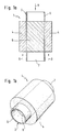
- Figs. 1A and 1B show a preferred embodiment of a heat exchanger basic module 1 which is part of the heat exchanger according to the invention described below.
- the basic heat exchanger module 1 has a tubular boundary wall 2 with a circular cross section.
- the tubular boundary wall 2 or the pipe section 2 is surrounded by a tubular outer packing 4 made of porous, flowable sintered metal, which also has a circular cross section.
- the pack 4 does not enclose the entire length of the tubular boundary wall 2.
- the interior of the pipe section 2 is filled with an inner pack 6 made of porous, flowable sintered metal. Again, not the entire length of the pipe section 2 but only part of it is filled with sintered metal.
- FIG. 1 shows a preferred embodiment of a heat exchanger basic module 1 which is part of the heat exchanger according to the invention described below.
- the basic heat exchanger module 1 has a tubular boundary wall 2 with a circular cross section.
- the tubular boundary wall 2 or the pipe section 2 is surrounded by a tub
- the length of the filling or the covering of the pipe section 2 by the outer or inner packing made of sintered metal is the same.
- the parts of the pipe section 2 that are not enveloped or filled by the packs 4 and 6 form connecting pieces 5 and 7.
- the boundary wall is sintered.
- the sintering of the packs 4 and 6 with the boundary wall or the pipe section 2 ensures an optimal heat transfer.
- the inside of the pipe section 2 forms an inner flow channel 8 for the heat-emitting or heat-absorbing side.
- the position of the outer packing 4 defines an outer flow channel 9.
- FIG. 2A and 2B show a first embodiment of a module receiving part of a heat exchanger according to the invention in a modular design.
- 2A shows one half of a module receiving part 10 from the inside and
- FIG. 2B shows the entire module receiving part 10 consisting of two parts according to FIG. 2A in a section along the line AA from FIG. 2A.
- the module receiving part 10 has a module holder 12, into which, for example, two heat exchanger basic modules 1 are releasably inserted, which are placed one behind the other with adjoining connecting pieces 5 and 7 in the module receiving part.
- the two basic modules are sealed or welded to one another in such a way that the interior of the tube pieces 2 together form a continuous flow channel.
- the various flow channels for the heat-absorbing or heat-absorbing medium can be seen from FIG. 2A.
- the connecting pieces 5 and 7 of the heat exchanger basic module 1 open into areas 14 and 15, into which the medium guided in the inner flow channel 8 is supplied or from which this medium is removed.
- the medium flowing through the outer packing 4 of sintered metal is supplied or discharged in annular regions 16 and 17.
- the two basic modules 1 are inserted into one half of the module receiving part 10 and the two parts or halves of the module receiving part 10 are assembled as shown in FIG. 2B and screwed together by means of screws 18.
- the two parts of the module receiving part 10 or the flow channels for the heat-absorbing or heat-dissipating medium are sealed by seals 19. Alternatively, the two parts can also be welded if there are special tightness requirements.
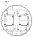
- FIG. 3A and 3B show a second and a third embodiment of a heat exchanger level according to the present invention.
- FIG. 3A shows, in an analogous representation to FIG. 2A, a half 20a of a module receiving part 20 for nine basic heat exchanger modules 1 arranged in the form of a spoke, only one basic heat exchanger module 1 being shown.
- 3B shows a perspective illustration of a disassembled heat exchanger plane with the two halves 20a and 20b of a module receiving part 20 in which eight heat exchanger basic modules 1 can be inserted into module holders 22 in the manner of the spokes of a wheel.
- the module receiving part 20 has an annular cylindrical shape with an inner cylinder wall 24 and an outer cylinder wall 25.
- the connectors 5 and 7 of the heat exchanger basic modules 1 pass through the inner cylinder wall 24 and the outer cylinder wall 25.
- the heat transport medium flowing in the inner flow channels 8 is supplied in the region of the inner cylinder wall 24 and flows via the connectors 5 into the inner flow channels 8
- the heat transfer medium flows out of the heat exchanger level again via the connection pieces 7.
- the heat transport medium flowing through the outer packing 4 of sintered metal is supplied or discharged in regions 26 and 27.
- 3A or 3B can be used particularly advantageously if a particularly good pressure balance between the individual modules is desired, since the flow paths of the individual basic heat exchanger modules are completely identical.
- the heat exchanger level can be inserted into a tubular or cylindrical pressure jacket 28.
- Fig. 4 shows a fourth embodiment of a heat exchanger level with a module receiving part 30 consisting of two halves 30a and 30b.
- four basic heat exchanger modules 1 are inserted into module holders 32 in the module receiving part 30.
- the axes of the inner flow channels 8 of the individual heat exchanger basic modules 1 lie in the module receiving part 30 with a circular cross section parallel to the sides of an inscribed square.
- the connecting pieces 5 of the heat exchanger basic modules 1 open into a region 33a of a first inlet duct and into a region 35a of a second inlet duct for the heat transport medium flowing in the inner flow duct 8.
- the connectors 7 of the heat exchanger basic modules 1 open out in a region 33b of a first outlet duct and in a region 35b of a second outlet duct.
- the heat transport medium flowing in the outer flow channel 9 is supplied in a region 36 or 37 and withdrawn from the collecting region 38 again from the heat exchanger or the heat exchanger level.
- the heat transfer medium is guided in counter-current in the heat exchanger basic modules 1.
- FIG. 5 shows a further embodiment of a half 40a of a module receiving part 40 of a heat exchanger level, which, like the heat exchanger level of FIG. 3B, offers space for eight basic heat exchanger modules 1.
- the outside diameter of the module receiving part 20 is smaller than the outside diameter of the module receiving part 20.
- the connecting pieces 5 of the heat exchanger basic modules 1 open into a region 42, via which the heat transport medium flowing in the inner flow channel 8 is supplied.
- the connecting pieces 7 of the heat exchanger basic modules 1 open into an area 44 or 45 from which the heat transport medium flowing in the inner flow channel 8 is withdrawn.
- the heat transport medium flowing in the outer flow channel 9 is supplied in a region 46 and withdrawn from regions 48 and 49, respectively.
- the basic heat exchanger module 50 has a tubular boundary wall 52.
- the tubular boundary wall 52 or the tube piece 52 is surrounded by a tubular outer packing 54 made of porous, flowable sintered metal, which is slightly conical in shape.
- the packing 54 does not enclose the entire length of the tubular boundary wall 52.
- the interior of the pipe section 52 is filled with an inner packing 56 made of porous, flowable sintered metal.
- the packs 54 and 56 are sintered with the boundary wall or the pipe section 52 in order to achieve an optimal heat transfer between the two packs 54 and To enable 56 of sintered metal over the boundary wall 52.
- the parts of the pipe section 52 which are not enveloped or filled by the packs 54 and 56 form connecting pieces 55 and 57.
- the interior of the pipe section 52 forms an inner flow channel 58 for the heat-emitting or heat-absorbing side.
- the position of the outer packing 54 defines an outer flow channel 59.
- the basic heat exchanger module 50 corresponds to the basic module 1.
- FIG. 7 shows a section through a further embodiment of a heat exchanger level consisting of a one-piece module receiving part 60 into which a conically shaped basic heat exchanger module 50 can be inserted.
- the heat transport media are conducted in countercurrent or cocurrent through the flow channels 58 and 59, respectively.
- Flow channels 62 are provided for this purpose.
- FIG. 8 schematically shows a further embodiment of a heat exchanger level with a module receiving part 70 consisting of two halves 70a and 70b, in which seven basic heat exchanger modules 50 are arranged vertically in module holders 72. That is, the axes of the inner flow channels are arranged perpendicular to the plane in which the two halves 70a and 70b of the module receptacle 70 are folded together.
- the heat transport medium flows through the outer flow channel of the heat exchanger basic modules 50 and is collected in the area 52 and can be fed to a separation mechanism, not shown.
- the heat transport medium flowing in the inner flow channel can also be passed through channels 74 and 75.
- circumferential flow channels are provided which correspond to the channels 62 in their function.
- a vertical section through the module holders 72 corresponds to the sectional illustration according to FIG. 7.
- the embodiment according to FIG. 8 is particularly suitable for cold evaporators. It could be empirically determined that an otherwise unchanged basic heat exchanger module 50 for cold evaporation of R12 for the cooling of compressed air yielded approximately 20% higher K values if, according to the embodiment of FIGS. 7A, 7B and 8 was arranged vertically with a steam guide from bottom to top and not horizontally. At the same time, the steam could be overheated up to 5 ° C without resulting in a measurable deterioration in the air outlet temperature.
Landscapes
- Engineering & Computer Science (AREA)
- Physics & Mathematics (AREA)
- Thermal Sciences (AREA)
- Mechanical Engineering (AREA)
- General Engineering & Computer Science (AREA)
- Chemical & Material Sciences (AREA)
- Dispersion Chemistry (AREA)
- Heat-Exchange Devices With Radiators And Conduit Assemblies (AREA)
- Physical Or Chemical Processes And Apparatus (AREA)
Claims (12)
- Echangeur de chaleur à construction modulaire avec au moins un plan d'échangeur de chaleur qui présente respectivement une pièce réceptrice de modules (10 ; 20 ; 30 ; 40 ; 60) avec des modules de base d'échangeurs de chaleur (1 ; 50) montés dedans, les modules de base d'échangeurs de chaleur (1 ; 50) présentant une paroi de limitation (2 ; 52) à travers lequel se produit la transmission thermique depuis la face de l'échangeur de chaleur émettant de la chaleur jusqu'à la face de l'échangeur de chaleur recevant de la chaleur, au moins une face de la paroi de limitation (2 ; 52) étant munie d'une garniture (4, 6 ; 54, 56) en materiau fritté poreux pouvant être traversé formant un premier canal d'écoulement (9) et la pièce réceptrice de modules (10 ; 20 ; 30 ; 40 ; 60) determinant avec les modules de base (1 ; 50) un second canal d'écoulement (8) pour les faces de l'échangeur de chaleur émettant de la chaleur et/ou recevant de la chaleur,
caractérisé en ce que la pièce réceptrice de modules (10 ; 20 ; 30 ; 40 ; 60) est en deux parties et enferme les modules de base de l'échangeur de chaleur à la manière de deux demi-coquilles, qui sont rendues étanches l'une par rapport à l'autre et présentent des zones d'arrivée ou respectivement de départ d'écoulement (14, 15 ou respectivement 16, 17) pour le milieu guidé dans les premier et second canaux d'écoulement (8 ou respectivement 9), dans lesquelles débouchent des pièces de raccordement (5, 7) des modules de base d'échangeurs de chaleur (1 50). - Echangeur de chaleur à construction modulaire selon la revendication 1,
caractérisé en ce que la paroi de limitation (2 ; 52) du module de base d'échangeur de chaleur détermine un canal d'écoulement tubulaire, en particulier à section circulaire, pour la face émettant de la chaleur ou recevant de la chaleur. - Echangeur de chaleur à construction modulaire selon la revendication 2,
caractérisé en ce que la garniture (4, 6 ; 54, 56) en matériau fritté poreux pouvant être traversé entoure à la manière d'un tuyau une partie de l'étendue longitudinale du canal d'écoulement tubulaire et/ou remplit complètement la section transversale à l'intérieur du canal d'écoulement tubulaire sur une partie de son étendue longitudinale. - Echangeur de chaleur à construction modulaire selon l'une des revendications 2 et 3,
caractérisé en ce que les modules de base d'échangeurs de chaleur individuels sont disposés verticalement côte à côte dans la pièce réceptrice de modules (10 ; 20 ; 30 ; 40 ; 60) à la manière d'un échangeur de chaleur à faisceau tubulaire. - Echangeur de chaleur à construction modulaire selon la revendication 4,
caractérisé en ce que les modules de base sont formes concaves. - Echangeur de chaleur à construction modulaire selon l'une des revendications 2 et 3,
caractérisé en ce que les modules de base individuels sont disposés côte à côte dans un plan dans la pièce réceptrice de modules (10 ; 20 ; 30 ; 40 ; 60). - Echangeur de chaleur à construction modulaire selon la revendication 6,
caractérisé en ce que les modules de base sont disposés dans la pièce réceptrice de modules (10 ; 20 ; 30 ; 40 ; 60) à la manière des rayons d'une roue. - Echangeur de chaleur à construction modulaire selon l'une des revendications précédentes,
caractérisé en ce que la paroi de limitation (2 ; 52) est constituée en aluminium et la garniture (4, 6 ; 54, 56) ou respectivement les garnitures en métal fritté est constituée ou respectivement sont constituées de poudre ou de granulat d'aluminium fritté poreux. - Echangeur de chaleur à construction modulaire selon l'une des revendications précédentes,
caractérisé en ce que la pièce réceptrice de modules (10 ; 20 ; 30 ; 40 ; 60) présente une section transversale circulaire. - Echangeur de chaleur à construction modulaire selon l'une des revendications précédentes,
caractérisé en ce que les garnitures en metal fritté sont recouvertes d'une substance catalytique. - Echangeur de chaleur à construction modulaire selon l'une des revendications précédentes,
caractérisé en ce que les plans d'échangeurs de chaleur individuels sont différents en ce qui concerne la structure et la caractéristique de puissance. - Echangeur de chaleur à construction modulaire selon l'une des revendications précédentes,
caractérisé en ce que les plans d'échangeurs de chaleur individuels sont disposés à l'intérieur d'un blindage commun.
Applications Claiming Priority (3)
| Application Number | Priority Date | Filing Date | Title |
|---|---|---|---|
| DE3939674 | 1989-11-30 | ||
| DE3939674A DE3939674C2 (de) | 1989-11-30 | 1989-11-30 | Wärmetauscher in Modulbauweise |
| PCT/DE1990/000930 WO1991008432A1 (fr) | 1989-11-30 | 1990-11-30 | Echangeur de chaleur a metal fritte |
Publications (2)
| Publication Number | Publication Date |
|---|---|
| EP0524926A1 EP0524926A1 (fr) | 1993-02-03 |
| EP0524926B1 true EP0524926B1 (fr) | 1995-01-11 |
Family
ID=6394539
Family Applications (1)
| Application Number | Title | Priority Date | Filing Date |
|---|---|---|---|
| EP90917118A Expired - Lifetime EP0524926B1 (fr) | 1989-11-30 | 1990-11-30 | Echangeur de chaleur a metal fritte |
Country Status (4)
| Country | Link |
|---|---|
| EP (1) | EP0524926B1 (fr) |
| AT (1) | ATE117070T1 (fr) |
| DE (2) | DE3939674C2 (fr) |
| WO (1) | WO1991008432A1 (fr) |
Families Citing this family (5)
| Publication number | Priority date | Publication date | Assignee | Title |
|---|---|---|---|---|
| JP2682361B2 (ja) * | 1992-12-09 | 1997-11-26 | 日本鋼管株式会社 | 排熱回収型燃焼装置 |
| JP2682362B2 (ja) * | 1992-12-09 | 1997-11-26 | 日本鋼管株式会社 | 排熱回収型燃焼装置 |
| IL108860A (en) * | 1994-03-04 | 1998-10-30 | Elisra Gan Ltd | Heat radiating element |
| DE102004010383B4 (de) * | 2004-03-03 | 2007-04-12 | Man Dwe Gmbh | Vorrichtung zur Simulierung des Reaktionsprozesses in und Verfahren zur Optimierung von Mantelrohrreaktoren |
| DE102012014813B9 (de) | 2012-07-26 | 2016-06-16 | Wieland-Werke Ag | Strukturierte Kühlkörper in Modulbauweise |
Family Cites Families (8)
| Publication number | Priority date | Publication date | Assignee | Title |
|---|---|---|---|---|
| DE7227102U (de) * | 1972-12-21 | Sintermetallwerk Krebsoege Gmbh | Filter aus Sintermetall | |
| FR1300303A (fr) * | 1961-06-22 | 1962-08-03 | Centre Nat Rech Scient | Perfectionnements aux échangeurs de chaleur |
| US3339260A (en) * | 1964-11-25 | 1967-09-05 | Olin Mathieson | Method of producing heat exchangers |
| US3493042A (en) * | 1967-04-11 | 1970-02-03 | Olin Mathieson | Modular units and use thereof in heat exchangers |
| GB1250114A (fr) * | 1969-02-18 | 1971-10-20 | ||
| GB1452290A (en) * | 1973-10-24 | 1976-10-13 | Advanced Materials Eng | Rotor for rotary regenerative heat exchanger |
| DE8001502U1 (de) * | 1980-01-22 | 1981-07-08 | Meineke, Ferdinand, Dipl.-Ing., 5608 Radevormwald | Wärmetauscher, insbesondere für Solarabsorber oder Zuluftwärmeanlagen mittels Abluft |
| DE3435319A1 (de) * | 1984-09-26 | 1986-04-03 | Michael 4150 Krefeld Laumen | Katalytischer dampferzeuger |
-
1989
- 1989-11-30 DE DE3939674A patent/DE3939674C2/de not_active Expired - Fee Related
-
1990
- 1990-11-30 AT AT90917118T patent/ATE117070T1/de not_active IP Right Cessation
- 1990-11-30 DE DE59008270T patent/DE59008270D1/de not_active Expired - Fee Related
- 1990-11-30 EP EP90917118A patent/EP0524926B1/fr not_active Expired - Lifetime
- 1990-11-30 WO PCT/DE1990/000930 patent/WO1991008432A1/fr active IP Right Grant
Also Published As
| Publication number | Publication date |
|---|---|
| DE3939674C2 (de) | 1995-06-08 |
| DE3939674A1 (de) | 1991-06-06 |
| WO1991008432A1 (fr) | 1991-06-13 |
| ATE117070T1 (de) | 1995-01-15 |
| DE59008270D1 (de) | 1995-02-23 |
| EP0524926A1 (fr) | 1993-02-03 |
Similar Documents
| Publication | Publication Date | Title |
|---|---|---|
| DE60310876T2 (de) | Getauchter verdampfer mit integriertem wärmeaustauscher | |
| EP3585509B1 (fr) | Échangeur de chaleur et réacteur | |
| DE3839966A1 (de) | Hohlfadenmodul | |
| DE2452734B2 (de) | Heizzylinder | |
| CH657207A5 (de) | Regenerator mit einem umlaufenden, regenerativen waermetauscher. | |
| WO2016131786A1 (fr) | Échangeur de chaleur à faisceau tubulaire | |
| DE2722288A1 (de) | Plattenfoermiger verdampfer | |
| EP2379978B1 (fr) | Distributeur de fluides a symetrie de rotation | |
| EP0524926B1 (fr) | Echangeur de chaleur a metal fritte | |
| DE3536316A1 (de) | Oelkuehler in scheibenbauweise | |
| DE2814326A1 (de) | Poroese abstuetzung zur verwendung in einer trenneinrichtung mit hohlfasern | |
| WO1992000129A1 (fr) | Element de colonne destine a recevoir des echangeurs de chaleur a plaques | |
| DE2524080C3 (de) | Wärmeübertrager, in dem ein dampfförmiges Medium unter Wärmeabgabe an ein anderes Medium kondensiert | |
| DE3042557C2 (de) | Wärmetauscher, insbesondere für Sonnenkraftwerke | |
| DE2805817A1 (de) | Rekuperativer waermeuebertrager aus keramischem material | |
| DE19650086C1 (de) | Wärmeübertrager | |
| DE2414295C2 (de) | Wärmeaustauscher zur Kondensation von Dampf | |
| DE102016103719B4 (de) | Vorrichtung zur Fluidführung | |
| EP0394758B1 (fr) | Echangeur de chaleur | |
| EP0130404A2 (fr) | Echangeur de chaleur à plusieurs étages | |
| EP3822569B1 (fr) | Echangeur de chaleur | |
| CH641893A5 (en) | Heat exchanger element, method for producing it, and a heat exchanger | |
| DE2121473A1 (de) | Röhrenwärmeaustauscher | |
| EP0230982B1 (fr) | Echangeur de chaleur cylindrique, fabriqué avec des éléments de construction préfabriqués, en particulier récupérateur sur cheminée | |
| DE1601167C3 (de) | Mischwärmetauscher |
Legal Events
| Date | Code | Title | Description |
|---|---|---|---|
| PUAI | Public reference made under article 153(3) epc to a published international application that has entered the european phase |
Free format text: ORIGINAL CODE: 0009012 |
|
| 17P | Request for examination filed |
Effective date: 19921116 |
|
| AK | Designated contracting states |
Kind code of ref document: A1 Designated state(s): AT BE CH DE DK ES FR GB GR IT LI LU NL SE |
|
| 17Q | First examination report despatched |
Effective date: 19930215 |
|
| GRAA | (expected) grant |
Free format text: ORIGINAL CODE: 0009210 |
|
| AK | Designated contracting states |
Kind code of ref document: B1 Designated state(s): AT BE CH DE DK ES FR GB GR IT LI LU NL SE |
|
| PG25 | Lapsed in a contracting state [announced via postgrant information from national office to epo] |
Ref country code: GR Free format text: LAPSE BECAUSE OF FAILURE TO SUBMIT A TRANSLATION OF THE DESCRIPTION OR TO PAY THE FEE WITHIN THE PRESCRIBED TIME-LIMIT Effective date: 19950111 Ref country code: ES Free format text: THE PATENT HAS BEEN ANNULLED BY A DECISION OF A NATIONAL AUTHORITY Effective date: 19950111 Ref country code: DK Effective date: 19950111 |
|
| REF | Corresponds to: |
Ref document number: 117070 Country of ref document: AT Date of ref document: 19950115 Kind code of ref document: T |
|
| REF | Corresponds to: |
Ref document number: 59008270 Country of ref document: DE Date of ref document: 19950223 |
|
| ITF | It: translation for a ep patent filed |
Owner name: SOCIETA' ITALIANA BREVETTI S.P.A. |
|
| GBT | Gb: translation of ep patent filed (gb section 77(6)(a)/1977) |
Effective date: 19950202 |
|
| ET | Fr: translation filed | ||
| PG25 | Lapsed in a contracting state [announced via postgrant information from national office to epo] |
Ref country code: SE Effective date: 19950411 |
|
| PLBE | No opposition filed within time limit |
Free format text: ORIGINAL CODE: 0009261 |
|
| STAA | Information on the status of an ep patent application or granted ep patent |
Free format text: STATUS: NO OPPOSITION FILED WITHIN TIME LIMIT |
|
| PG25 | Lapsed in a contracting state [announced via postgrant information from national office to epo] |
Ref country code: LU Free format text: LAPSE BECAUSE OF NON-PAYMENT OF DUE FEES Effective date: 19951130 |
|
| 26N | No opposition filed | ||
| PGFP | Annual fee paid to national office [announced via postgrant information from national office to epo] |
Ref country code: CH Payment date: 19981118 Year of fee payment: 9 |
|
| PGFP | Annual fee paid to national office [announced via postgrant information from national office to epo] |
Ref country code: FR Payment date: 19981119 Year of fee payment: 9 |
|
| PGFP | Annual fee paid to national office [announced via postgrant information from national office to epo] |
Ref country code: AT Payment date: 19981123 Year of fee payment: 9 |
|
| PGFP | Annual fee paid to national office [announced via postgrant information from national office to epo] |
Ref country code: GB Payment date: 19981125 Year of fee payment: 9 |
|
| PGFP | Annual fee paid to national office [announced via postgrant information from national office to epo] |
Ref country code: NL Payment date: 19981130 Year of fee payment: 9 |
|
| PGFP | Annual fee paid to national office [announced via postgrant information from national office to epo] |
Ref country code: BE Payment date: 19981210 Year of fee payment: 9 |
|
| PGFP | Annual fee paid to national office [announced via postgrant information from national office to epo] |
Ref country code: DE Payment date: 19990121 Year of fee payment: 9 |
|
| PG25 | Lapsed in a contracting state [announced via postgrant information from national office to epo] |
Ref country code: LI Free format text: LAPSE BECAUSE OF NON-PAYMENT OF DUE FEES Effective date: 19991130 Ref country code: GB Free format text: LAPSE BECAUSE OF NON-PAYMENT OF DUE FEES Effective date: 19991130 Ref country code: CH Free format text: LAPSE BECAUSE OF NON-PAYMENT OF DUE FEES Effective date: 19991130 Ref country code: BE Free format text: LAPSE BECAUSE OF NON-PAYMENT OF DUE FEES Effective date: 19991130 Ref country code: AT Free format text: LAPSE BECAUSE OF NON-PAYMENT OF DUE FEES Effective date: 19991130 |
|
| BERE | Be: lapsed |
Owner name: KWW G.- FUR THERMOTECHNIK M.B.H. Effective date: 19991130 |
|
| PG25 | Lapsed in a contracting state [announced via postgrant information from national office to epo] |
Ref country code: NL Free format text: LAPSE BECAUSE OF NON-PAYMENT OF DUE FEES Effective date: 20000601 |
|
| REG | Reference to a national code |
Ref country code: CH Ref legal event code: PL |
|
| GBPC | Gb: european patent ceased through non-payment of renewal fee |
Effective date: 19991130 |
|
| PG25 | Lapsed in a contracting state [announced via postgrant information from national office to epo] |
Ref country code: FR Free format text: LAPSE BECAUSE OF NON-PAYMENT OF DUE FEES Effective date: 20000731 |
|
| NLV4 | Nl: lapsed or anulled due to non-payment of the annual fee |
Effective date: 20000601 |
|
| PG25 | Lapsed in a contracting state [announced via postgrant information from national office to epo] |
Ref country code: DE Free format text: LAPSE BECAUSE OF NON-PAYMENT OF DUE FEES Effective date: 20000901 |
|
| REG | Reference to a national code |
Ref country code: FR Ref legal event code: ST |
|
| PG25 | Lapsed in a contracting state [announced via postgrant information from national office to epo] |
Ref country code: IT Free format text: LAPSE BECAUSE OF NON-PAYMENT OF DUE FEES;WARNING: LAPSES OF ITALIAN PATENTS WITH EFFECTIVE DATE BEFORE 2007 MAY HAVE OCCURRED AT ANY TIME BEFORE 2007. THE CORRECT EFFECTIVE DATE MAY BE DIFFERENT FROM THE ONE RECORDED. Effective date: 20051130 |