EP0524274B1 - Mit einem elektrischen antriebsmotor ausgerüstete vorrichtung - Google Patents
Mit einem elektrischen antriebsmotor ausgerüstete vorrichtung Download PDFInfo
- Publication number
- EP0524274B1 EP0524274B1 EP92902300A EP92902300A EP0524274B1 EP 0524274 B1 EP0524274 B1 EP 0524274B1 EP 92902300 A EP92902300 A EP 92902300A EP 92902300 A EP92902300 A EP 92902300A EP 0524274 B1 EP0524274 B1 EP 0524274B1
- Authority
- EP
- European Patent Office
- Prior art keywords
- terminals
- stator
- electrical
- coil
- pins
- Prior art date
- Legal status (The legal status is an assumption and is not a legal conclusion. Google has not performed a legal analysis and makes no representation as to the accuracy of the status listed.)
- Expired - Lifetime
Links
Images
Classifications
-
- H—ELECTRICITY
- H02—GENERATION; CONVERSION OR DISTRIBUTION OF ELECTRIC POWER
- H02K—DYNAMO-ELECTRIC MACHINES
- H02K3/00—Details of windings
- H02K3/46—Fastening of windings on the stator or rotor structure
- H02K3/52—Fastening salient pole windings or connections thereto
- H02K3/521—Fastening salient pole windings or connections thereto applicable to stators only
- H02K3/524—Fastening salient pole windings or connections thereto applicable to stators only for U-shaped, E-shaped or similarly shaped cores
-
- H—ELECTRICITY
- H02—GENERATION; CONVERSION OR DISTRIBUTION OF ELECTRIC POWER
- H02K—DYNAMO-ELECTRIC MACHINES
- H02K11/00—Structural association of dynamo-electric machines with electric components or with devices for shielding, monitoring or protection
- H02K11/20—Structural association of dynamo-electric machines with electric components or with devices for shielding, monitoring or protection for measuring, monitoring, testing, protecting or switching
- H02K11/25—Devices for sensing temperature, or actuated thereby
Definitions
- the present invention relates to an apparatus provided with an electric drive motor.
- the electric drive motor generally comprises on the one hand a permanent magnet rotor supported by the body of the apparatus and on the other hand a stator comprising a core in U-shaped magnetic sheets, an electrical coil consisting either of a single coil of electrical wire mounted on the central part of the U of this magnetic core or by two coils of wire in series mounted on the two branches of the U of this magnetic core and a protective cover, the electrical winding being provided with electrical connection terminals or pins.
- the fragile winding of the stator is often protected by a cover at the end of the operation only.
- the device is frequently delivered on request with electrical connection terminals or pins oriented either towards the front side or towards the rear side of this device and arranged either according to a standard or to another standard.
- the known device is usually manufactured with several forms of body and protective cover, which increases its cost price and results in expensive storage of these parts.
- a French patent application 2,580,424 discloses an electric coil device with several connection positions and an electric motor using such a device.
- the present invention aimed at avoiding the above drawbacks makes it possible to produce an appliance with an electric drive motor at an economical price.
- this device is provided with a single body shape and a single form of protective casing for the electric winding of this drive motor and capable of satisfying different requests for orientation of the electrical connection terminals. forward or rearward and arrangement thereof according to a standard or another standard.
- This device is provided with a structure which facilitates mechanization or robotization of assembly and / or manufacture of several of its elements.
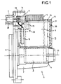
- the rotor 4 supported in rotation by the body 2 drives a impeller, not shown, of a pump 8 mounted in the front part of the device 1, and the stator provided with its electric winding 6 is mounted astride the body 2 around this rotor 4.
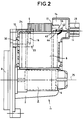
- an apparatus provided with an electric drive motor 1 comprises a casing 10 integral with the stator, forming with the latter an autonomous stator sub-assembly 13 which is protected against external aggressions by this casing 10 and which has two diametrically opposed ways of assembling this autonomous stator sub-assembly on the body 2 of the device 1, a way making it possible to orient the electrical connection terminals or pins 11 of the winding 6 towards the front part of the device 1 ( Figure 1) and a way to orient these terminals or electrical connection pins to the rear of the device 1 ( Figure 2).
- This autonomous stator sub-assembly 13 comprises the casing 10, the magnetic core 5 in a U, the electrical winding 6 protected against external aggressions by this casing 10, an optional thermal protector 12, a multinorm electrical connector 14 and mechanical means for fixing this autonomous stator sub-assembly to the body 2 of the device 1, such as symmetrical lateral bosses for hooking in front 15 and rear 16, carried by the casing 10.
- the electric winding 6 is constituted either by a single coil of electric wire not shown mounted on the central part or bottom of the U or on a branch of the U of the magnetic core 5 or by two twin coils of electric wire in series 19, 20 schematically illustrated in FIGS. 7 to 10, mounted on the two branches of the U of this magnetic core 5.
- a thermal protector of an optionally known type 12 is preferably arranged in an available space existing between the two twin coils 19, 20 of the electric winding 6.
- a multinorm electrical connector 14 comprises, on the one hand, electrical connection terminals or pins 11 of the electrical winding 6 and / or of the thermal protector 12 fixed in a projection 17 of a cheek 24 of a coil not shown or of the projections 17 of the adjacent cheeks 24 electrically insulators of twin coils 19, 20, those of the cheeks which are furthest from the axis 25 of the body 2 of the apparatus 1, that is to say close to the bottom of the U of the magnetic core 5 so as to be distant from the body 2 of the device 1 and thus make it possible to avoid any spatial interference between this body 2 and the multinorm electrical connector 14, and on the other hand sliding guides 28 formed in a projecting end of the casing 10 for plugs electrical connection females of a known type not shown which are threaded on these electrical connection terminals or pins 11.
- the casing 10 made of an electrically insulating and resistant to mechanical shock material covers both the electrical winding 6 and the electrical connection terminals or pins 11 and protects them.
- This envelope 10 comprises a perforated cover 30 mounted on its walls 31 pivoting on hinges not shown or removable by assembly by interlocking. This perforated cover 30 allows a stream of cooling air to flow through the stator.
- the autonomous stator sub-assembly 13 with its two opposite assembly paths on the body 2 of the device makes it possible to easily respond to requests for orientation of the electrical connection terminals or pins 11 forwards or backwards.
- the device 1. The symmetrical lateral hooking bosses front 15 and rear 16 carried by the casing 10 make it possible to retain and block in place the autonomous stator sub-assembly 13 on the body 2 of the device by hooking to associated ears 33 carried by this body 2.
- the apparatus 1 is thus particularly economical in manufacture and advantageous in storage since only one form of the body 2 of the apparatus 1 and only one form of the casing 10 of the sub- autonomous stator assembly 13 are sufficient to make this device 1 capable of responding to requests for orientation of the terminals or electrical connection pins 11 forwards or backwards.
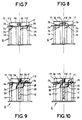
- the multinorm electrical connector 14 is produced according to two standards, a standard standard and a standard known in the designation "RAST5"
- the terminals or connection pins 11 constituting input or output terminals or pins S are flat and have on the one hand predetermined spacings relatively small for the "RAST5" standard (FIGS. 8 and 10) and relatively large for the standard standard (FIGS. 7 and 9) and on the other hand a parallel flat arrangement according to the standard standard and a parallel edge arrangement according to the "RAST5" standard.
- a first end of the winding 6 is welded to a known terminal onto which a first electrical supply wire of the thermal protector 12 has come soldered. In this case, this first end of the winding 6 undergoes two consecutive damaging heatings welding.
- the multi-standard electrical connector 14 of the device 1 comprises on the one hand in one or more projections 17 of the adjacent cheeks 24 of twin coils 19, 20 of the electric coil 6 four identical holes or slots 36 arranged in pairs according to two standards, for example, a standard standard and a standard "RAST5" and intended to receive and fix terminals or pins of electrical connection 11, and on the other hand three identical terminals or pins of electrical connection 11 of which the first two terminals are respectively connected to the two ends 34, 35 of the electrical winding 6 (FIGS. 7 to 10) and the third terminal is connected to the first 38 of the two supply wires 38, 39 of an optional thermal protector 12 when a combination of this thermal protector 12 to the electrical winding 6 is requested (FIGS. 9 and 10), the second supply wire 39 of this thermal protector 12 being connected to one of these first two terminals or bro electrical connections 11.
- two standards for example, a standard standard and a standard "RAST5" and intended to receive and fix terminals or pins of electrical connection 11, and on the other hand three identical terminals or pins of
- the first two connection terminals or pins 11 connected respectively to the two ends 34, 35 of the electrical winding 6 and mounted in two holes or slots 36 of the projections 17 of the cheeks 24 of twin coils 19, 20 constitute in the multinorm electrical connector 14, terminals or pins 11E input and 11S output connection according to a standard in Figure 7 and according to a "RAST5" standard in Figure 8.
- one of the first two terminals or connection pins 11 connected to the first 34 of the ends 34, 35 of the electric winding 6 and mounted in a hole or slot 36 of the projections 17 of the cheeks 24 of twin coils 19, 20 and the third connection terminal or pin 11 connected to the first 38 of the two supply wires of this thermal protector 12 and mounted in another hole or slot 36 of these projections 17 of the cheeks 24 of twin coils 19,20 constitute in the multinorm electrical connector 14 terminals or pins for connection of output 11S and input 11E according to a standard standard in FIG.
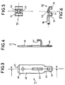
- an electrical connection terminal or pin 11, made of a resilient mechanical and elastic metal comprises a flat body 40 provided in its central zone with a cut and raised tongue 42, in a first fixing end or end 43, of a cut and raised blocking lug 44 and in a second connection end or end 46, of a point beveled 47.
- the tongue 42 is ready for fixing one end of an electric coil 6 by welding or stapling and the lug 44 is intended to lock in place the flat body 40, that is to say the terminal or pin 11 when its fixing end 43 is fully engaged in a slot or hole 36 of the projections 7 of the cheeks 24 of twin coils 19,20 ( Figure 2).
- the bevelled tip 47 facilitates reception of a female plug for electrical connection.
- lugs or clips 50 provide an electrical connection between the two supply wires 38, 39 of a thermal protector 12 and the connection terminals or pins 11 by threading or press fitting on the latter.
- a terminal or clip 50 made of an elastic and mechanically resistant metal comprises a flat body 51 provided in its central part, with cut and raised lugs 53 intended for fixing by welding, stapling or crimping of one of the two supply wires 38, 39 of the thermal protector 12 and in its longitudinal edges of side tabs curved inward 55, 56.
- a terminal or connection pin 11 of the electrical connector 14 When threading or fitting the terminal or clip 50 on a terminal or connection pin 11 of the electrical connector 14, its curved side tabs 55, 56 which push and elastically apply the flat body 40 of this connection terminal or pin 11 against the flat body 51 of this terminal or clip 50, thus achieving good electrical connection contact.
- the two supply wires of a thermal protector 12 are first fixed respectively on two lugs or clips 50, then when this thermal protector is connected, these lugs or clips 50 are fitted or threaded to force on the terminals or connection pins 11 of the multinorm electrical connector 14. All these operations can be easily and advantageously mechanized or robotic.
- the thermal protector 12 Since in the autonomous stator sub-assembly 13, the thermal protector 12 is usually electrically connected in series with the electric winding 6 of the stator, it then suffices in the first place to thread the first of these two lugs or clips 50 connected to this thermal protector 12 on a connection terminal or pin 11 of the multinorm electrical connector 14, which carries the first of the two ends of the electric winding 6 of the stator, and consequently transform this terminal or pin into an intermediate connection terminal or pin 11I, secondly, threading the second of these two lugs or clips 50 onto a terminal or pin 11 free from any electrical connection with the electrical winding 6 and transforming this terminal or pin into an input connection terminal or pin 11E, and thirdly to mount the connection terminal or pin 11 which carries the second of the two ends of the electric winding 6 of the stator in the connector electric multinorm 14 and transform it into a terminal or output connection pin 11S ( Figures 9 and 10). All these operations are also easily and advantageously mechanized or robotic.
- the lug or clip 50 threaded or fitted on the terminal or pin 11 makes it possible to avoid an electrical winding 6 of a stator, two damaging consecutive heatings in an electrical connection in series of a thermal protector 12 and of this electric coil 6 by welding, while facilitating mechanization or robotization of these operations.
Landscapes
- Engineering & Computer Science (AREA)
- Power Engineering (AREA)
- Microelectronics & Electronic Packaging (AREA)
- Motor Or Generator Frames (AREA)
- Insulation, Fastening Of Motor, Generator Windings (AREA)
- Lens Barrels (AREA)
- Lock And Its Accessories (AREA)
- Connection Of Motors, Electrical Generators, Mechanical Devices, And The Like (AREA)
Claims (10)
- Gerät mit einem elektrischen Antriebsmotor (3) und einem Körper (2), wobei der Motor (3) ein Schutzgehäuse (10) enthält, dadurch gekennzeichnet, daß das Gehäuse (10), da der Stator (5, 6) des Motors an dem Körper angebracht ist, vor der Montage des Stators an dem Körper (2) fest mit dem Stator (5, 6) verbunden wird, wobei das Gehäuse (10) mit dem Stator (5, 6) eine unabhängige Stator-Unterbaugruppe (13) bildet, die gegen äußere Angriffe geschützt ist und zwei zueinander diametral entgegengesetzte Wege zum Einbauen der unabhängigen Stator-Unterbaugruppe (13) in den Körper (2) aufweist, wobei ein Weg ermöglicht, die elektrischen Verbindungsklemmen oder -stifte (11) einer Wicklung (6) des Stators zum vorderen Abschnitt des Geräts auszurichten, und wobei ein Weg ermöglicht, diese zum hinteren Abschnitt des Geräts auszurichten.
- Gerät nach Anspruch 1, dadurch gekennzeichnet, daß die unabhängige Stator-Unterbaugruppe (13) das Gehäuse (10) umfaßt, wobei der Stator einen U-förmigen magnetischen Kern (5) und eine elektrische Wicklung (6) umfaßt sowie eine optionale Wärme-Schutzvorrichtung (12) für diese Wicklung, einen elektrischen Mehrnormen-Verbinder (14) dieser Wärme-Schutzvorrichtungen (12) und der Wicklung (6) und Mittel zum Befestigen der unabhängigen Unterbaugruppe (13) an dem Körper (2) des Geräts.
- Gerät nach Anspruch 2, dadurch gekennzeichnet, daß in der unabhängigen Stator-Unterbaugruppe (13) das Gehäuse (10), welches gleichzeitig die elektrische Wicklung (6) und die elektrischen Verbindungsklemmen oder -stifte (11) abdeckt, eine durchbrochene Abdeckung (30) umfaßt, die einen Luftstrom zum Kühlen des Stators hindurchtreten läßt, sowie zueinander symmetrische, seitliche vordere Vorsprünge (15) und seitliche hintere Vorsprünge (16), die als Mittel zur Befestigung der unabhängigen Stator-Unterbaugruppe (13) an dem Körper (2) des Geräts dienen.
- Gerät nach Anspruch 2, dadurch gekennzeichnet, daß der elektrische Mehrnormen-Verbinder (14) der unabhängigen Stator-Unterbaugruppe (13) zum einen elektrische Verbindungsklemmen oder -stifte (11) der elektrischen Wicklung (6) und/ oder der Wärme-Schutzvorrichtung (12) umfaßt, die in einem oder mehreren Vorsprüngen (17) von dem Satz oder von den benachbarten Sätzen (24) der Spule der elektrischen Wicklung (6) befestigt sind, die von der Achse (25) des Körpers (2) des Geräts am weitesten entfernt sind, und zum anderen Gleitführungen (28), die an einem hervorstehenden Ende (10) für elektrische Anschluß-Steckbuchsen ausgebildet sind, die auf die elektrischen Verbindungsklemmen oder -stifte(11) aufgeschoben sind.
- Gerät nach einem der Ansprüche 2 und 4, dadurch gekennzeichnet, daß bei der unabhängigen Stator-Unterbaugruppe (13) der gemäß zweier Normen, beispielsweise einer Standardnorm und einer "RAST5" genannten Norm, ausgebildete elektrische Mehrnormen-Verbinder (14) zum einen in dem Vorsprung oder den Vorsprüngen (17) des Satzes oder der benachbarten Sätze (24) der Spule der elektrischen Wicklung (6) vier identische Löcher oder Schlitze (36) umfaßt, die paarweise gemäß den beiden Normen angeordnet und dafür ausgelegt sind, die elektrischen Verbindungsklemmen oder -stifte (11) aufzunehmen und zu befestigen, und zum anderen drei identische elektrische Verbindungsklemmen oder -stifte (11), von denen die beiden ersten Klemmen oder Stifte mit zwei Enden (34, 35) der elektrischen Wicklung (6) verbunden sind und die dritte Klemme oder der dritte Stift mit dem ersten (38) von zwei Versorgungsdrähten (38, 39) der optionalen Wärme-Schutzvorrichung (12), wenn eine Verbindung dieser Wärme-Schutzvorrichtung (12) mit der elektrischen Wicklung (6) gewünscht ist, verbunden ist und eine Verbindungseingangsklemmen oder einen Verbindungseingangsstift (11E) bildet, wobei der zweite Versorgungsdraht (39) der Wärme-Schutzvorrichtung (12) mit einer oder einem der beiden ersten elektrischen Verbindungsklemmen oder Verbindungsstifte (11) verbunden ist, um diese oder diesen in eine Verbindungszwischenklemme oder einen Verbindungszwischenstift (11I) zu transformieren, wobei die andere oder der andere der beiden ersten Klemmen oder Stifte eine Verbindungsausgangsklemme oder einen Verbindungsausgangsstift (11S) bildet.
- Gerät nach einem der Ansprüche 4 und 5, dadurch gekennzeichnet, daß in dem elektrischen Mehrnormen-Verbinder (14) die identischen Verbindungsklemmen oder -stifte (11) einen flachen Körper (40) umfassen, der in seiner Mittelzone mit einer ausgeschnittenen und hervortretenden Zunge (42) versehen ist, die zum Befestigen eines der Enden der elektrischen Wicklung (6) ausgebildet ist, sowie an einem ersten Ende (43) mit einem ausgeschnittenen und hervortretenden Vorsprung (44), der ein Blockieren des flachen Körpers (40) an seinem Ort gewährleistet, und an einem zweiten Ende (46) mit einer angefasten Spitze (47), die das Aufnehmen einer elektrischen Anschluß-Steckbuchse erleichtert.
- Gerät nach einem der Ansprüche 5 und 6, dadurch gekennzeichnet, daß der elektrische Mehrnormen-Verbinder (14) Kabelschuhe oder Clips (50) umfaßt, die eine elektrische Verbindung zwischen den beiden Versorgungsdrähten (38, 39) einer Wärme-Schutzvorrichtung (12) und den Verbindungsklemmen oder -stiften (11) durch Aufschieben oder Aufstecken auf die letztgenannten gewährleisten.
- Gerät nach Anspruch 7, dadurch gekennzeichnet, daß in dem elektrischen Mehrnormen-Verbinder (14) ein Kabelschuh oder Clip (50) einen flachen Körper (51) umfaßt, der in seinem Mittelabschnitt mit ausgeschnittenen und hervortretenden Vorsprüngen (53) versehen ist, die für eine Verbindung mit einem der beiden Versorgungsdrähte (38, 39) der Wärme-Schutzvorrichtung (12) vorgesehen sind, und an seinen Längsrändern mit nach innen umgebogenen Seitenlaschen (55, 56).
- Gerät nach einem der Ansprüche 1 und 2, dadurch gekennzeichnet, daß das Gehäuse (10) der unabhängigen Stator-Unterbaugruppe (13) aus einem elektrisch isolierenden und gegen mechanische Schläge widerstandsfähigen Material ausgebildet ist.
- Gerät nach einem der Ansprüche 4 bis 8, dadurch gekennzeichnet, daß die Verbindungsklemmen oder -stifte (11) und die Kabelschuhe oder Clips (50) des elektrischen Mehrnormen-Verbinders (14) aus einem elastischen und mechanisch widerstandsfähigen Material ausgebildet sind.
Applications Claiming Priority (3)
| Application Number | Priority Date | Filing Date | Title |
|---|---|---|---|
| FR9016133 | 1990-12-12 | ||
| FR9016133A FR2670961A1 (fr) | 1990-12-21 | 1990-12-21 | Appareil muni d'un moteur electrique d'entrainement. |
| PCT/FR1991/001022 WO1992011683A1 (fr) | 1990-12-21 | 1991-12-17 | Appareil muni d'un moteur electrique d'entrainement |
Publications (2)
| Publication Number | Publication Date |
|---|---|
| EP0524274A1 EP0524274A1 (de) | 1993-01-27 |
| EP0524274B1 true EP0524274B1 (de) | 1995-09-20 |
Family
ID=9403558
Family Applications (1)
| Application Number | Title | Priority Date | Filing Date |
|---|---|---|---|
| EP92902300A Expired - Lifetime EP0524274B1 (de) | 1990-12-21 | 1991-12-17 | Mit einem elektrischen antriebsmotor ausgerüstete vorrichtung |
Country Status (8)
| Country | Link |
|---|---|
| US (1) | US5382855A (de) |
| EP (1) | EP0524274B1 (de) |
| AT (1) | ATE128285T1 (de) |
| CA (1) | CA2076348A1 (de) |
| DE (1) | DE69113260T2 (de) |
| ES (1) | ES2077393T3 (de) |
| FR (1) | FR2670961A1 (de) |
| WO (1) | WO1992011683A1 (de) |
Families Citing this family (14)
| Publication number | Priority date | Publication date | Assignee | Title |
|---|---|---|---|---|
| JPH07177720A (ja) * | 1993-12-22 | 1995-07-14 | Matsushita Electric Ind Co Ltd | ブラシレスモータ |
| US5818142A (en) * | 1995-07-27 | 1998-10-06 | Black & Decker Inc. | Motor pack armature support with brush holder assembly |
| DE19621450A1 (de) * | 1996-05-29 | 1997-12-04 | Teves Gmbh Alfred | Elektrisches Anschlußelement |
| US6020670A (en) * | 1998-08-17 | 2000-02-01 | General Electric Co. | Connector support block for limiting deflection of a main lead connector in an electric machine |
| US6681799B2 (en) | 2001-09-21 | 2004-01-27 | Siemens Vdo Automotive, Inc. | Exhaust gas regulator including an overmolded housing |
| DE10152006B4 (de) * | 2001-10-22 | 2011-06-01 | Zf Sachs Ag | Stator für eine elektrische Maschine |
| US6664679B2 (en) * | 2002-05-10 | 2003-12-16 | Siemens Westinghouse Power Corporation | Dynamoelectric machine including insulator and associated methods |
| US7224532B2 (en) * | 2002-12-06 | 2007-05-29 | Chevron U.S.A. Inc. | Optical uses diamondoid-containing materials |
| DE102004015541B4 (de) * | 2003-04-01 | 2012-06-21 | Aisan Kogyo K.K. | Schrittmotor und Strömungsregelungsventil, das einen solchen Schrittmotor aufweist |
| JP4531359B2 (ja) * | 2003-07-18 | 2010-08-25 | 三菱電機株式会社 | モータ |
| DE102007038746A1 (de) * | 2007-08-16 | 2009-02-26 | Pierburg Gmbh | Elektrische Verbrennungskraftmaschinen-Stellanordnung |
| JP5556833B2 (ja) * | 2012-03-09 | 2014-07-23 | 株式会社デンソー | 回転式アクチュエータ |
| US9577493B2 (en) | 2012-09-20 | 2017-02-21 | Black & Decker Inc. | Motor and electronics cooling system for a high power cordless nailer |
| JP6317579B2 (ja) * | 2013-03-28 | 2018-04-25 | 日本電産サンキョー株式会社 | モータにおけるカバー構造 |
Family Cites Families (9)
| Publication number | Priority date | Publication date | Assignee | Title |
|---|---|---|---|---|
| FR2312133A1 (fr) * | 1975-05-23 | 1976-12-17 | Thomson Brandt | Machine electrique tournante pourvue d'un systeme de protection de bobinage |
| DE3335035C2 (de) * | 1983-09-28 | 1986-11-06 | Ebm Elektrobau Mulfingen Gmbh & Co, 7119 Mulfingen | Anordnung zum Verbinden der Drahtenden einer Statorwicklung von Elektromotoren mittels Steckverbinder |
| FR2580424B1 (fr) * | 1985-04-12 | 1987-08-07 | Nivernais Electromecanique | Dispositif de bobines electriques a plusieurs positions de connexion et moteur electrique utilisant un tel dispositif |
| DE8633206U1 (de) * | 1986-12-11 | 1987-02-26 | Licentia Patent-Verwaltungs-Gmbh, 6000 Frankfurt, De | |
| JPH066689Y2 (ja) * | 1987-10-21 | 1994-02-16 | 三菱電機株式会社 | 小型電動機 |
| JP2844610B2 (ja) * | 1988-09-14 | 1999-01-06 | 松下電器産業株式会社 | モールドモータ |
| EP0472746B1 (de) * | 1990-08-17 | 1994-05-04 | Siemens Aktiengesellschaft | Elektromotor, insbesondere feuchtigkeitsdicht geschlossener Kommutatormotor zum Antrieb einer axial angeflanschten Hydraulik-Pumpe |
| JP2534683Y2 (ja) * | 1990-07-16 | 1997-05-07 | 愛三工業株式会社 | ステップモータのターミナル固定構造 |
| US5220224A (en) * | 1991-12-30 | 1993-06-15 | North American Philips Corporation | Stepper motor with integrated assembly |
-
1990
- 1990-12-21 FR FR9016133A patent/FR2670961A1/fr active Granted
-
1991
- 1991-12-17 US US07/923,890 patent/US5382855A/en not_active Expired - Fee Related
- 1991-12-17 CA CA002076348A patent/CA2076348A1/fr not_active Abandoned
- 1991-12-17 DE DE69113260T patent/DE69113260T2/de not_active Expired - Fee Related
- 1991-12-17 AT AT92902300T patent/ATE128285T1/de active
- 1991-12-17 ES ES92902300T patent/ES2077393T3/es not_active Expired - Lifetime
- 1991-12-17 EP EP92902300A patent/EP0524274B1/de not_active Expired - Lifetime
- 1991-12-17 WO PCT/FR1991/001022 patent/WO1992011683A1/fr active IP Right Grant
Also Published As
| Publication number | Publication date |
|---|---|
| FR2670961A1 (fr) | 1992-06-26 |
| CA2076348A1 (fr) | 1992-06-22 |
| DE69113260T2 (de) | 1996-02-15 |
| WO1992011683A1 (fr) | 1992-07-09 |
| FR2670961B1 (de) | 1993-02-26 |
| EP0524274A1 (de) | 1993-01-27 |
| US5382855A (en) | 1995-01-17 |
| ES2077393T3 (es) | 1995-11-16 |
| DE69113260D1 (de) | 1995-10-26 |
| ATE128285T1 (de) | 1995-10-15 |
Similar Documents
| Publication | Publication Date | Title |
|---|---|---|
| EP0524274B1 (de) | Mit einem elektrischen antriebsmotor ausgerüstete vorrichtung | |
| US8002575B2 (en) | Cable assembly with strain relief member | |
| FR2656171A1 (de) | ||
| FR2516313A1 (fr) | Ensemble de blindage pour connecteur electrique et procede de realisation d'une terminaison sur un cable totalement blinde | |
| FR3071112A1 (fr) | Systeme de connexion pour machine electrique. | |
| FR2492157A1 (fr) | Dispositif combine de demarrage et de protection de moteur electrique monophase utilisant une thermistance de demarrage | |
| EP0772256B1 (de) | Elektrisches Gerät mit Anschlussklemmen, die durch eine Blende mit Flügeln geschützt sind | |
| FR3013157A1 (fr) | Connecteur electrique a reprise de blindage | |
| FR2773859A1 (fr) | Embrayage electromagnetique | |
| KR870001348Y1 (ko) | 콘넥터 | |
| EP2135326B1 (de) | Leitfähige vorrichtung für den elektrischen kontakt einer leiterabschirmungsummantelung | |
| FR2514956A1 (fr) | Dispositif de connexion a enfichage | |
| FR2465505A1 (fr) | Perfectionnements apportes aux petits moteurs electriques, notamment pour les voitures de course miniatures | |
| EP1100105B1 (de) | Verdrahtungsvorrichtung für Schutzschaltung | |
| EP1925011A1 (de) | Wärmekraftmaschinenanlasserschalter mit verbesserten elektrischen verbindungsmitteln der wicklung | |
| EP0420058B1 (de) | Elektrisches Sicherheitssteckdosensystem | |
| FR2604570A1 (fr) | Element de couverture pour espaces interpolaires | |
| US6454602B1 (en) | High voltage bulkhead connector | |
| FR2646554A1 (fr) | Moyens de connexion des enroulements primaires d'une bobine d'allumage, en particulier pour moteur a combustion interne de vehicule automobile | |
| KR20050084235A (ko) | 케이블 커넥터 및 이러한 커넥터를 조합하기 위한 방법 | |
| EP0721239B1 (de) | Herstellungsverfahren für einen Kabelsteckverbinder, elektrisches Kabel und Hochspannungstransformator mit solchen Kabeln | |
| JPH1014154A (ja) | 電気機器のリード線の支持装置 | |
| FR2738405A3 (fr) | Cordon d'alimentation electrique et appareil muni d'un tel cordon | |
| FR3026601A1 (fr) | Dispositif electrique modulaire ou chaque module est destine a etre fixe a un support respectif, et systeme electrique comportant un tel dispositif electrique | |
| JP3338959B2 (ja) | コイル素子の接続構造 |
Legal Events
| Date | Code | Title | Description |
|---|---|---|---|
| PUAI | Public reference made under article 153(3) epc to a published international application that has entered the european phase |
Free format text: ORIGINAL CODE: 0009012 |
|
| 17P | Request for examination filed |
Effective date: 19920912 |
|
| AK | Designated contracting states |
Kind code of ref document: A1 Designated state(s): AT CH DE ES FR GB IT LI |
|
| 17Q | First examination report despatched |
Effective date: 19940630 |
|
| GRAA | (expected) grant |
Free format text: ORIGINAL CODE: 0009210 |
|
| RIN1 | Information on inventor provided before grant (corrected) |
Inventor name: COUSIN, JOEL |
|
| AK | Designated contracting states |
Kind code of ref document: B1 Designated state(s): AT CH DE ES FR GB IT LI |
|
| REF | Corresponds to: |
Ref document number: 128285 Country of ref document: AT Date of ref document: 19951015 Kind code of ref document: T |
|
| REF | Corresponds to: |
Ref document number: 69113260 Country of ref document: DE Date of ref document: 19951026 |
|
| ITF | It: translation for a ep patent filed |
Owner name: JACOBACCI & PERANI S.P.A. |
|
| REG | Reference to a national code |
Ref country code: ES Ref legal event code: FG2A Ref document number: 2077393 Country of ref document: ES Kind code of ref document: T3 |
|
| GBT | Gb: translation of ep patent filed (gb section 77(6)(a)/1977) |
Effective date: 19951127 |
|
| PLBI | Opposition filed |
Free format text: ORIGINAL CODE: 0009260 |
|
| PLBF | Reply of patent proprietor to notice(s) of opposition |
Free format text: ORIGINAL CODE: EPIDOS OBSO |
|
| 26 | Opposition filed |
Opponent name: FAGOR, S.COOP Effective date: 19960613 |
|
| PGFP | Annual fee paid to national office [announced via postgrant information from national office to epo] |
Ref country code: GB Payment date: 19961119 Year of fee payment: 6 |
|
| PGFP | Annual fee paid to national office [announced via postgrant information from national office to epo] |
Ref country code: DE Payment date: 19961120 Year of fee payment: 6 |
|
| PGFP | Annual fee paid to national office [announced via postgrant information from national office to epo] |
Ref country code: CH Payment date: 19961210 Year of fee payment: 6 |
|
| PGFP | Annual fee paid to national office [announced via postgrant information from national office to epo] |
Ref country code: FR Payment date: 19961220 Year of fee payment: 6 Ref country code: ES Payment date: 19961220 Year of fee payment: 6 |
|
| PGFP | Annual fee paid to national office [announced via postgrant information from national office to epo] |
Ref country code: AT Payment date: 19961230 Year of fee payment: 6 |
|
| PG25 | Lapsed in a contracting state [announced via postgrant information from national office to epo] |
Ref country code: GB Free format text: LAPSE BECAUSE OF NON-PAYMENT OF DUE FEES Effective date: 19971217 Ref country code: AT Free format text: LAPSE BECAUSE OF NON-PAYMENT OF DUE FEES Effective date: 19971217 |
|
| PG25 | Lapsed in a contracting state [announced via postgrant information from national office to epo] |
Ref country code: LI Free format text: LAPSE BECAUSE OF NON-PAYMENT OF DUE FEES Effective date: 19971231 Ref country code: FR Free format text: THE PATENT HAS BEEN ANNULLED BY A DECISION OF A NATIONAL AUTHORITY Effective date: 19971231 Ref country code: CH Free format text: LAPSE BECAUSE OF NON-PAYMENT OF DUE FEES Effective date: 19971231 |
|
| PLBO | Opposition rejected |
Free format text: ORIGINAL CODE: EPIDOS REJO |
|
| PLBN | Opposition rejected |
Free format text: ORIGINAL CODE: 0009273 |
|
| STAA | Information on the status of an ep patent application or granted ep patent |
Free format text: STATUS: OPPOSITION REJECTED |
|
| GBPC | Gb: european patent ceased through non-payment of renewal fee |
Effective date: 19971217 |
|
| 27O | Opposition rejected |
Effective date: 19980327 |
|
| REG | Reference to a national code |
Ref country code: CH Ref legal event code: PL |
|
| PG25 | Lapsed in a contracting state [announced via postgrant information from national office to epo] |
Ref country code: DE Free format text: LAPSE BECAUSE OF NON-PAYMENT OF DUE FEES Effective date: 19980901 |
|
| REG | Reference to a national code |
Ref country code: FR Ref legal event code: ST |
|
| PG25 | Lapsed in a contracting state [announced via postgrant information from national office to epo] |
Ref country code: ES Free format text: LAPSE BECAUSE OF NON-PAYMENT OF DUE FEES Effective date: 19981218 |
|
| REG | Reference to a national code |
Ref country code: ES Ref legal event code: FD2A Effective date: 19990114 |
|
| PG25 | Lapsed in a contracting state [announced via postgrant information from national office to epo] |
Ref country code: IT Free format text: LAPSE BECAUSE OF NON-PAYMENT OF DUE FEES;WARNING: LAPSES OF ITALIAN PATENTS WITH EFFECTIVE DATE BEFORE 2007 MAY HAVE OCCURRED AT ANY TIME BEFORE 2007. THE CORRECT EFFECTIVE DATE MAY BE DIFFERENT FROM THE ONE RECORDED. Effective date: 20051217 |