EP0523577A2 - Connection between a bolt and a supporting member and oscillating bearing - Google Patents
Connection between a bolt and a supporting member and oscillating bearing Download PDFInfo
- Publication number
- EP0523577A2 EP0523577A2 EP92111844A EP92111844A EP0523577A2 EP 0523577 A2 EP0523577 A2 EP 0523577A2 EP 92111844 A EP92111844 A EP 92111844A EP 92111844 A EP92111844 A EP 92111844A EP 0523577 A2 EP0523577 A2 EP 0523577A2
- Authority
- EP
- European Patent Office
- Prior art keywords
- bolt
- connection
- screw
- axle
- vehicle
- Prior art date
- Legal status (The legal status is an assumption and is not a legal conclusion. Google has not performed a legal analysis and makes no representation as to the accuracy of the status listed.)
- Withdrawn
Links
Images

Classifications
-
- B—PERFORMING OPERATIONS; TRANSPORTING
- B60—VEHICLES IN GENERAL
- B60G—VEHICLE SUSPENSION ARRANGEMENTS
- B60G9/00—Resilient suspensions of a rigid axle or axle housing for two or more wheels
- B60G9/02—Resilient suspensions of a rigid axle or axle housing for two or more wheels the axle or housing being pivotally mounted on the vehicle, e.g. the pivotal axis being parallel to the longitudinal axis of the vehicle
-
- B—PERFORMING OPERATIONS; TRANSPORTING
- B60—VEHICLES IN GENERAL
- B60G—VEHICLE SUSPENSION ARRANGEMENTS
- B60G7/00—Pivoted suspension arms; Accessories thereof
- B60G7/02—Attaching arms to sprung part of vehicle
-
- F—MECHANICAL ENGINEERING; LIGHTING; HEATING; WEAPONS; BLASTING
- F16—ENGINEERING ELEMENTS AND UNITS; GENERAL MEASURES FOR PRODUCING AND MAINTAINING EFFECTIVE FUNCTIONING OF MACHINES OR INSTALLATIONS; THERMAL INSULATION IN GENERAL
- F16C—SHAFTS; FLEXIBLE SHAFTS; ELEMENTS OR CRANKSHAFT MECHANISMS; ROTARY BODIES OTHER THAN GEARING ELEMENTS; BEARINGS
- F16C11/00—Pivots; Pivotal connections
- F16C11/02—Trunnions; Crank-pins
-
- B—PERFORMING OPERATIONS; TRANSPORTING
- B60—VEHICLES IN GENERAL
- B60G—VEHICLE SUSPENSION ARRANGEMENTS
- B60G2204/00—Indexing codes related to suspensions per se or to auxiliary parts
- B60G2204/40—Auxiliary suspension parts; Adjustment of suspensions
- B60G2204/44—Centering or positioning means
- B60G2204/4402—Spacers or shims
-
- F—MECHANICAL ENGINEERING; LIGHTING; HEATING; WEAPONS; BLASTING
- F16—ENGINEERING ELEMENTS AND UNITS; GENERAL MEASURES FOR PRODUCING AND MAINTAINING EFFECTIVE FUNCTIONING OF MACHINES OR INSTALLATIONS; THERMAL INSULATION IN GENERAL
- F16C—SHAFTS; FLEXIBLE SHAFTS; ELEMENTS OR CRANKSHAFT MECHANISMS; ROTARY BODIES OTHER THAN GEARING ELEMENTS; BEARINGS
- F16C2326/00—Articles relating to transporting
- F16C2326/01—Parts of vehicles in general
- F16C2326/05—Vehicle suspensions, e.g. bearings, pivots or connecting rods used therein
Landscapes
- Engineering & Computer Science (AREA)
- Mechanical Engineering (AREA)
- General Engineering & Computer Science (AREA)
- Pivots And Pivotal Connections (AREA)
Abstract
Description
Die Erfindung betrifft die Verbindung zwischen einem Bolzen und einem Tragteil, wobei wenigstens ein Teil des Bolzens über die Oberfläche des Tragteils hinausragt und zur Aufnahme wenigstens eines Bauteils, durch das im wesentlichen quer zur Bolzenachse wirkende Kräfte einleitbar sind, geeignet ist. Ferner betrifft die Erfindung die Pendellagerung für eine Fahrzeugachse, insbesondere für die Vorderachse eines landwirtschaftlichen oder Nutzfahrzeuges, mit wenigstens einer zwischen einem Achsträger des Fahrzeuges und der Fahrzeugachse angeordneten schwenkbaren Bolzenverbindung, bei der ein Bolzen starr mit dem Achsträger oder mit der Fahrzeugachse verbunden ist und in eine Ausnehmung der Fahrzeugachse oder des Achsträgers eingreift.The invention relates to the connection between a bolt and a support part, at least part of the bolt projecting beyond the surface of the support part and being suitable for receiving at least one component by means of which forces acting transversely to the bolt axis can be introduced. Furthermore, the invention relates to the pendulum mounting for a vehicle axle, in particular for the front axle of an agricultural or commercial vehicle, with at least one pivotable pin connection arranged between an axle carrier of the vehicle and the vehicle axle, in which a pin is rigidly connected to the axle carrier or to the vehicle axle and in engages a recess of the vehicle axle or the axle support.
Es ist bekannt, die Verbindung eines Bolzens mit einem Tragteil durch eine Preßpassung herzustellen, indem ein Schaft des Bolzens in eine entsprechende Bohrung im Tragteil eingepreßt wird. Soll der Bolzen hohe, quer zur Bolzenachse wirkende Kräfte aufnehmen, so muß eine Mindesteinpreßtiefe gegeben sein, um eine sichere Verbindung zu gewährleisten. Dies hat zur Folge, daß eine ausreichende Dicke des Tragteils gegeben sein muß.It is known to produce a connection between a bolt and a support part by means of an interference fit, in that a shaft of the bolt is pressed into a corresponding bore in the support part. If the bolt is to absorb high forces acting transversely to the bolt axis, a minimum insertion depth must be given in order to ensure a secure connection. The consequence of this is that the supporting part must have a sufficient thickness.
Derartige bekannte Verbindungen finden beispielsweise bei der Pendellagerung der Vorderachse eines Ackerschleppers Anwendung, bei der ein Pendelbolzen in den Vorderachsträger eingepreßt ist. Über den Pendelbolzen ist der Achskörper mit seiner Bohrung aufschiebbar. Zur Aufnahme des Schleppergewichtes ist eine hohe Kräfte aufnehmende Preßpassung erforderlich, bei der die Mindesteinpreßtiefe von etwa dem einfachen des Bolzendurchmessers eingehalten werden muß. Daher muß die Aufnahme des Vorderachsträgers eine entsprechende Materialstärke und Materialqualität aufweisen.Known connections of this type are used, for example, in the pendulum mounting of the front axle of a tractor, in which a pendulum pin is pressed into the front axle support. The axle body with its hole can be pushed over the pendulum pin. To record the tractor weight, a high force-absorbing press fit is required, in which the minimum pressing depth of approximately the simple one of the bolt diameter must be observed. Therefore, the front axle support must have an appropriate material thickness and material quality.
Die mit der Erfindung zu lösende Aufgabe wird darin gesehen, eine kraftschlüssige Verbindung der eingangs genannten Art anzugeben, die lösbar und für relativ dünne Tragteile, an die geringe Materialqualitätsanforderungen gestellt werden, geeignet ist.The object to be achieved with the invention is seen in providing a non-positive connection of the type mentioned at the outset, which is detachable and suitable for relatively thin supporting parts to which low material quality requirements are imposed.
Die Aufgabe wird erfindungsgemäß dadurch gelöst, daß der Bolzen einen Bund enthält, dessen zum Tragteil gewandte Fläche mittels einer Schraubverbindung gegen eine Oberfläche des Tragteils gepreßt wird, wobei die Schraubverbindung eine zentral im Bolzen verlaufende und mit dem Tragteil zusammenwirkende Schraube aufweist. Hierbei wird die Schraube lediglich auf Zugspannung, nicht aber durch Scherkräfte beansprucht.The object is achieved in that the bolt contains a collar, the surface facing the support part is pressed by means of a screw connection against a surface of the support part, the screw connection having a central bolt which cooperates with the support part. Here, the screw is only subjected to tensile stress, but not to shear forces.
Die erfindungsgemäße Verbindung ist lösbar. Bei ihr werden die Momente, die infolge der quer zur Bolzenachse wirkenden Kräfte auftreten, nicht innerhalb einer Preßpassung aufgenommen. Vielmehr stützt sich der Bolzen durch den an ihm angeformten Bund auf der Oberfläche des Tragteils ab. Dies wird durch das Anpressen des Bolzens an das Tragteil mittels einer, wenn erforderlich, hochfesten Schraube ermöglicht. Die Querkräfte werden durch Reibschluß zwischen dem Bund und der Oberfläche des Tragteils aufgenommen. Für die von dem Bolzen auf das Tragteil übertragbaren Kräfte ist die Dicke des Tragteils nicht ausschlaggebend.The connection according to the invention is releasable. With it, the moments that occur as a result of the forces acting transversely to the pin axis are not taken up within an interference fit. Rather, the bolt is supported by the collar formed on it on the surface of the supporting part. This is made possible by pressing the bolt onto the supporting part by means of a high-strength screw, if necessary. The transverse forces are absorbed by friction between the collar and the surface of the support part. The thickness of the supporting part is not decisive for the forces that can be transmitted from the bolt to the supporting part.
Im zentralen Bereich des Bolzens läßt sich, selbst wenn der Bund in radialer Richtung relativ schmal ist, eine kräftige Schraubverbindung in Form einer Schraube unterbringen. Dies ermöglicht die Übertragung großer axialer Druckkräfte, durch die der Bund auf die Oberfläche des Tragteils gedrückt wird. Mit steigender Druckkraft steigen sowohl die aufnehmbaren Momente als auch der Reibschluß und damit auch die aufnehmbaren Querkräfte.In the central area of the bolt, even if the collar is relatively narrow in the radial direction Place a strong screw connection in the form of a screw. This enables the transmission of large axial compressive forces, by means of which the collar is pressed onto the surface of the supporting part. As the compressive force increases, both the moments that can be absorbed and the frictional engagement and thus also the transverse forces that can be absorbed increase.
Gemäß einer vereinfachten Betrachtung bildet sich aufgrund der Zugspannung der Schraubverbindung auf der Anlagefläche zwischen Bund und Tragteil ein homogenes Druckspannungsfeld aus. Diesem Druckspannungsfeld überlagert sich im Biegebelastungsfall das für die Biegebeanspruchung typische Zug-Druck-Spannungsfeld (Superpositionsprinzip).According to a simplified view, a homogeneous compressive stress field is formed on the contact surface between the collar and the supporting part due to the tensile stress of the screw connection. This compressive stress field is superimposed on the tensile-compressive stress field typical of the bending stress (superposition principle).
Das homogene Druckspannungsfeld soll ausreichend groß gewählt werden, damit bei maximaler Biegebeanspruchung in jedem Bereich der Anlagefläche die Druckspannung durch die Schraubverbindung größer ist als die Biegespannung. In extremen Fällen ist durch die Verbindung jedoch auch eine Biegebeanspruchung aufnehmbar, die zu einer einseitigen teilweisen Abhebung des Bundes von der Tragplatte führt. Festigkeitssteigernd für den Bolzen wirkt sich zudem die durch die Schraubenvorspannungskraft im Bolzen erzeugte Druckvorspannung aus.The homogeneous compressive stress field should be sufficiently large so that the compressive stress due to the screw connection is greater than the bending stress in every area of the contact surface at maximum bending stress. In extreme cases, however, the connection can also absorb a bending stress, which leads to a one-sided partial lifting of the collar from the support plate. The compressive preload generated by the bolt preload force in the bolt also increases the strength of the bolt.
Zweckmäßigerweise enthält der Bolzen einen zylindrischen Zapfen zur Aufnahme des Bauteils. Dieser Zapfen kann in eine Bohrung des die Querkräfte einleitenden Bauteils eingesteckt werden. Dabei kann die Verbindung zwischen Bolzen und dem Bauteil so ausgebildet werden, daß sich das Bauteil um die Bolzenachse verschwenken läßt. Diese Ausbildung eignet sich für die Pendellagerung einer Fahrzeugachse. Bei einer kostengünstigen Ausbildung ist der gesamte Bolzen mit Bund und Zapfen als Drehteil ausgebildet.The bolt expediently contains a cylindrical pin for receiving the component. This pin can be inserted into a hole in the component introducing the transverse forces. The connection between the bolt and the component can be designed so that the component can be pivoted about the bolt axis. This training is suitable for the self-aligning bearing of a vehicle axle. In the case of an inexpensive design, the entire bolt with the collar and pin is designed as a turned part.
Gemäß einer bevorzugten Ausgestaltung der Erfindung ist zwischen der Rückseite des Tragteils und dem Schraubenkopf bzw. einer auf die Schraube aufschraubbaren Mutter eine Scheibe angeordnet. Die an dem Tragteil anliegende Fläche der Scheibe ist zur Erzielung gleicher Flächenpressungen in etwa gleich groß wie die auf der anderen Seite an dem Tragteil anliegende Bundfläche. Die Scheibe dient der großflächigen Krafteinleitung in das Tragteil und ist insbesondere bei relativ dünnen Tragteilen und geringen Materialqualitäten von Vorteil.According to a preferred embodiment of the invention, a washer is arranged between the back of the supporting part and the screw head or a nut that can be screwed onto the screw. To achieve the same surface pressures, the surface of the disk resting on the support part is approximately the same size as the flange surface lying on the other side of the support part. The washer is used for the large-scale introduction of force into the supporting part and is particularly advantageous for relatively thin supporting parts and low material qualities.
Vorzugsweise ist eine weitere Scheibe vorgesehen, die mit der Schraube am freien Ende des Bolzens befestigbar ist und die sich radial über den Bolzenquerschnitt hinausragend erstreckt. Hierdurch kann das Bauteil zwischen Bund und Scheibe entweder fest eingespannt oder mit einem axialen Spiel, das eine Drehbewegung des Bauteils um die Zapfenachse zuläßt, eingeschlossen werden.A further disk is preferably provided which can be fastened with the screw at the free end of the bolt and which extends radially beyond the bolt cross section. As a result, the component between the collar and the disc can either be firmly clamped or enclosed with an axial play that allows the component to rotate about the pin axis.
Gemäß einer weiteren bevorzugten Ausgestaltung der Erfindung ist an den Bolzen auf der dem Tragteil zugewandten Seite des Bundes ein Stummel angeformt, der sich in eine dem Stummelquerschnitt entsprechende Ausnehmung des Tragteils erstreckt. Durch diesen Stummel können Querkräfte, die über das durch Reibschluß aufzunehmende Maß hinausgehen, auf das Tragteil übertragen werden. Der Stummel dient gleichzeitig der Positionierung und Zentrierung des Bolzens am Tragteil.According to a further preferred embodiment of the invention, a stub is formed on the bolt on the side of the collar facing the support part and extends into a recess of the support part corresponding to the stub cross section. Through this stub transverse forces that go beyond the amount to be absorbed by friction can be transmitted to the support member. The stub also serves to position and center the bolt on the supporting part.
Eine weitere mit der Erfindung zu lösende Aufgabe wird darin gesehen, eine Pendellagerung für eine Fahrzeugachse mit einer schwenkbaren Bolzenverbindung anzugeben, die lediglich relativ geringe Wandstärken des den Bolzen aufnehmenden Bauteils erfordert und ohne Ausdistanzieren mittels Beilagscheiben eine einfache rasche Montage unter Einhaltung der geforderten Montagemaße ermöglicht.Another object to be achieved with the invention is seen in specifying a self-aligning bearing for a vehicle axle with a pivotable bolt connection which only requires relatively small wall thicknesses of the component which receives the bolt and which allows simple, rapid assembly without spacing by means of washers while observing the required assembly dimensions.
Diese Aufgabe wird erfindungsgemäß durch die Verwendung einer Verbindung zwischen dem Bolzen und dem aufnehmenden Tragteil der erfindungsgemäßen Art gelöst. Eine derartige Verbindung ermöglicht eine einfache rasche Montage und Demontage des Bolzens und der Pendellagerung.This object is achieved by the use of a connection between the bolt and the receiving support part of the type according to the invention. Such a connection enables simple quick assembly and disassembly of the bolt and the pendulum bearing.
Bei bekannten Lagerungen ist gegebenenfalls das Ausdistanzieren einer zweiten Lagerstelle mittels Beilagscheiben erforderlich, da die freitragende (über die Tragteiloberfläche hinausragende) Bolzenlänge mit beim Einpressen auftretenden Montagetoleranzen behaftet ist. Bei der erfindungsgemäßen Pendellagerung ist die Toleranz der freitragenden Länge lediglich von der spanabhebenden Formgebung abhängig und damit ausreichend genau.In the case of known bearings, it may be necessary to distance a second bearing by means of washers, since the unsupported bolt length (which protrudes beyond the surface of the supporting part) is subject to assembly tolerances which occur during pressing. In the case of the self-aligning bearing according to the invention, the tolerance of the unsupported length depends only on the machining shape and is therefore sufficiently precise.
Wegen der hohen Belastung wird der Bolzen in der Regel oberflächengehärtet. Damit kann die dem Tragteil abgewandte Fläche des an dem Bolzen angeformten Bundes als Anlauffläche für das Lagerauge des angelenkten Bauteils dienen, ohne daß, wie bei bekannten Pendellagern üblich, ein gehärteter Anlaufring zwischengelegt werden muß.The bolt is usually surface hardened due to the high load. The surface facing away from the supporting part of the collar formed on the bolt can thus serve as a contact surface for the bearing eye of the articulated component without a hardened thrust ring having to be interposed, as is customary in known self-aligning bearings.
Vorzugsweise sind zwei zueinander fluchtende, in Fahrzeuglängsrichtung ausgerichtete erfindungsgemäße Verbindungen vorgesehen, wobei wenigstens eine Verbindung eine am freien Ende des Zapfens befestigbare, über den Querschnitt des Zapfens hinausragende Scheibe enthält.Preferably, two connections according to the invention, aligned with one another and oriented in the longitudinal direction of the vehicle, are provided, at least one connection containing a disk which can be fastened to the free end of the pin and projects beyond the cross section of the pin.
Ferner ist es von Vorteil, wenn die Bolzen am Achsträger befestigt und ihre Zapfen zur Fahrzeugrückseite ausgerichtet sind. Auf die Zapfen lassen sich Büchsen stecken. Der Achskörper enthält Lageraugen, die sich über die Büchsen schieben lassen.It is also advantageous if the bolts are attached to the axle carrier and their pins are aligned with the rear of the vehicle. Tins can be stuck on the pins. The axle body contains bearing eyes that can be pushed over the bushings.
Weitere vorteilhafte Ausgestaltungen und Weiterbildungen der Erfindung gehen aus den Unteransprüchen hervor.Further advantageous refinements and developments of the invention emerge from the subclaims.
Anhand der Zeichnung, die mehrere Ausführungsbeispiele der Erfindung zeigt, sollen die Erfindung sowie weitere Vorteile und vorteilhafte Weiterbildungen und Ausgestaltungen der Erfindung näher beschrieben und erläutert werden.On the basis of the drawing, which shows several exemplary embodiments of the invention, the invention and further advantages and advantageous developments and refinements of the invention are to be described and explained in more detail.
Es zeigt:
- Fig. 1
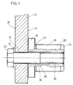
- den Teilschnitt durch eine erfindungsgemäße Verbindung zwischen einem Bolzen und einem Tragteil und
- Fig. 2
- den Teilschnitt der erfindungsgemäßen Pendellagerung für eine Fahrzeugachse mit zwei alternativen erfindungsgemäßen Bolzen-Fahrzeugchassis-Verbindungen.
- Fig. 1
- the partial section through an inventive connection between a bolt and a support part and
- Fig. 2
- the partial section of the self-aligning bearing according to the invention for a vehicle axle with two alternative bolt-vehicle chassis connections according to the invention.
In Fig. 1 ist der Teilbereich eines als Tragteil dienenden Gehäuses 10, Flansches oder dergleichen mit einer Durchgangsbohrung 12 dargestellt, an dessen einer Seite 14 eine Stirnfläche eines rotationssymmetrischen, mit der Durchgangsbohrung 12 fluchtenden Bolzens 16 anliegt. Der Bolzen 16 besteht im wesentlichen aus einem Bund 18 und einem Zapfen 20. Zwischen Bund 18 und Zapfen 20 befindet sich ein Freistich 22. Das freie Ende des Zapfens 20 ist mit einer kegelstumpfförmigen Phase 24 versehen, die das Einführen des Zapfens 20 in die Bohrung eines nicht dargestellten Bauteils, welches auf dem Zapfen 20 des Bolzens 16 verdrehbar gelagert werden kann, erleichtert.1 shows the partial area of a
Der Bolzen 16 weist eine axiale Bohrung auf, die in einen zylindrischen Abschnitt 26 und einen Gewindeabschnitt 28 unterteilt ist. Der Gewindeabschnitt 28 befindet sich im Bereich des freien Endes des Zapfens 20. Durch die Durchgangsbohrung 12 des Gehäuses 10 und die Bohrung des Bolzens 16 erstreckt sich eine Schraube 30, die in den Gewindeabschnitt 28 eingedreht ist. Der Schraubenkopf 32 stützt sich über eine Unterlegscheibe 34 an der dem Bolzen 16 abgewandten Fläche 36 des Gehäuses 10 ab.The
Bei der Schraube 30 handelt es sich um eine hochfeste, hohe Zugkräfte aufnehmende Schraube. Durch sie wird die dem Zapfen 20 abgewandte Stirnfläche des Bundes 18 gegen die Seite 14 des Gehäuses 10 gepreßt. Der als Anlagefläche dienende Bereich dieser Seite 14 des Gehäuses 10 kann mechanisch bearbeitet sein, um eine paßgenaue Anlage des Bolzens 16 zu gewährleisten.The
Eine hohe Zugspannung der Schraube 30 führt zu einem hohen Anlagedruck zwischen Bund 18 und Gehäuse 10. Dieser Anlagedruck bewirkt einen guten Reibschluß zwischen Bund 18 und Gehäuse 10, der die Aufnahme hoher Querkräfte, die von dem nicht gezeigten Bauteil auf den Bolzen 16 übertragen werden, erlaubt. Die auftretenden Momente stützen sich über den Bund 18 als Normalkräfte an der Seite 14 der Tragplatte 10 ab. Dabei gilt, je größer der Durchmesser des Bundes 18, desto größer die übertragbaren Momente.A high tension of the
Aus der Fig. 2 geht eine Pendellagerung für die lenkbare Vorderachse eines Ackerschleppers hervor, die in einem längs zur Fahrtrichtung verlaufenden Schnitt gezeigt ist. Das Vorderachsmittelstück 40, welches mit den Vorderrädern 42 des nicht näher dargestellten Ackerschleppers in Verbindung steht, stützt sich über zwei erfindungsgemäße Verbindungen 44 und 46 an zwei Laschen 48, 50 ab, die Teil eines nicht näher dargestellten Vorderachsträgers und somit des Fahrzeugchassis sind.2 shows a pendulum mounting for the steerable front axle of a tractor, which is shown in a section running longitudinally to the direction of travel. The front
Die Verbindungen 44, 46 enthalten je einen konzentrisch ausgebildeten Bolzen 52, 54, die im wesentlichen aus drei Abschnitten, nämlich einem Zapfen 56, 58, einem Bund 60, 62 und einem Stummel 64, 66 aufgebaut sind, wobei Zapfen 56, 58 und Stummel 64, 66 jeweils auf gegenüberliegenden Seiten des Bundes 60, 62 liegen. Die Stummel 64, 66 sind jeweils in eine Durchgangsbohrung der zugehörigen Lasche 48, 50 eingesteckt. Dabei liegt die dem Stummel 64, 66 zugewandte Stirnfläche des Bundes 60, 62 gegen die Seitenfläche 68, 70 der Lasche 48, 50 an.The
Durch den vorderen Bolzen 52 erstreckt sich eine nicht gezeigte, durchgehende, axiale, zylindrische Bohrung, die den Schaft einer Schraube 72 aufnimmt. Der hintere Bolzen 54 ist hinsichtlich seiner Durchgangsbohrung ähnlich gestaltet wie es anhand der Fig. 1 beschrieben wurde. In seinem Gewindeabschnitt ist eine Schraube 74 eingedreht. Die Schrauben 72, 74 dienen der Befestigung der Bolzen 52, 54 an den Laschen 48, 50.A continuous, axial, cylindrical bore (not shown) extends through the
Bei der vorderen Verbindung 44 stützt sich der Schraubenkopf 76 an einer Scheibe 78 ab, die an der freien Stirnfläche des Zapfens 56 anliegt und deren Außendurchmesser größer ist als der Durchmesser des Zapfens 56. Das Gewindeende 80 der Schraube 72 ragt über die dem Bolzen 52 abgewandte Seite 81 der Lasche 48 hinaus und trägt eine Druckscheibe 82 und eine Mutter 84. Durch Anziehen der Mutter 84 wird der Stummel 64 des Bolzens 52 in die Durchgangsbohrung der Lasche 48 gezogen und die Lasche 48 zwischen dem Bund 60 und der Druckscheibe 82 eingespannt.In the case of the
Bei der hinteren Verbindung 46 ist die Schraubverbindung zwischen Lasche 50 und Bolzen 54 ähnlich wie bei der Ausführung gemäß Fig. 1 gestaltet. Im Unterschied zu Fig. 1 befindet sich hier an Stelle der Unterlegscheibe 34 eine Druckscheibe 86, so daß die Lasche 50 zwischen Druckscheibe 86 und Bund 62 des Bolzens 54 eingespannt ist.In the
Das Vorderachsmittelstück 40 trägt ein vorderes nach oben gerichtetes Lagerauge 88 und ein hinteres nach oben gerichtetes Lagerauge 90. Die zylindrischen Durchgangsbohrungen beider Lageraugen 88, 90, in die Lagerbüchsen 92 eingepaßt sind, fluchten miteinander und sind in Fahrtrichtung des Ackerschleppers ausgerichtet. In den Lagerbüchsen 92 sind die Zapfen 56, 58 des zugehörigen Bolzens 52, 54 drehbar gelagert.The front
Das vordere Lagerauge 88 liegt zwischen dem Bund 60 des vorderen Bolzens 52 und der Scheibe 78. Ein geringes axiales Spiel ermöglicht ein Verdrehen des Lagerauges 88 über dem Bolzen 52. Die Abstandsverhältnisse der Laschen 48, 50 und Lageraugen 88, 90 sind so gewählt, daß zwischen dem hinteren Lagerauge 90 und dem Bund 62 des zugehörigen Bolzens 54 ein ausreichender Abstand gegeben ist, durch den ein Anliegen des Lagerauges 90 am Bund 62 vermieden wird.The
Die Stummel 64, 66 sind mit einer Gleit- oder auch Preßpassung in die Durchgangsbohrungen der Laschen 48, 50 eingepaßt, so daß nach Lösen der Schrauben 72, 74, die Bolzen 52, 54 aus den Laschen 48, 50 gezogen beziehungsweise mittels eines Dorns getrieben werden können. Sie dienen der Zentrierung der Bolzen 52, 54. Darüberhinaus sind sie in der Lage, von den Lageraugen 88, 90 auf die Bolzen 52, 54 übertragene Querkräfte, die über das durch Reibschluß aufzunehmende Maß hinausgehen, auf die Laschen 48, 50 weiterzuleiten.The
Der Durchmesser der Druckscheiben 82, 86 ist größer als der der Stummel 64, 66 und fast so groß wie der Durchmesser der Bünde 60, 62. Die Druckscheiben 82, 86 dienen der großflächigen Krafteinleitung der von den Schrauben 72, 74 aufgebrachten Zugkraft in die Laschen 48, 50.The diameter of the
Zur Montage der Vorderachse am Schlepperrumpf wird zunächst der hintere Bolzen 54 an der Lasche 50 befestigt, indem sein Stummel 66 in die Durchgangsbohrung der Lasche 50 eingeführt und dann die Schraube 74 in den Bolzen 54 eingeschraubt wird. Hierauf wird der vordere Bolzen 52 mit seinem Stummel 64 in die Durchgangsbohrung der vorderen Lasche 48 eingesetzt, ohne ihn jedoch zu verschrauben. Die Vorderachse wird in ihre Einbaulage gebracht, und die Lageraugen 88, 90, in die die Lagerbüchsen 92 eingesetzt sind, werden über die Zapfen 56, 58 geschoben. Nun wird die Schraube 72 mit der Scheibe 78 und der Druckscheibe 82 eingesetzt, und durch Festziehen der Mutter 84 wird der Bolzen 52 an der Lasche 48 befestigt.To assemble the front axle on the tractor fuselage, the rear bolt 54 is first attached to the
Die Demontage erfolgt in umgekehrter Reihenfolge, wobei jedoch in der Regel der hintere Bolzen 54 nicht von der Lasche 50 demontiert zu werden braucht. Für die Montage sind keine Distanzierungsmittel wie Beilagscheiben erforderlich. Als Werkzeug für die Montage wird lediglich ein gewöhnlicher Schraubenschlüssel benötigt.The disassembly is carried out in the reverse order, however as a rule the rear bolt 54 does not need to be removed from the
Auch wenn die Erfindung lediglich an Hand einiger Ausführungsbeispiele beschrieben wurde, erschließen sich für den Fachmann im Lichte der vorstehenden Beschreibung viele verschiedenartige Alternativen, Modifikationen und Varianten, die unter die vorliegende Erfindung fallen.Even if the invention has only been described with the aid of a few exemplary embodiments, many different alternatives, modifications and variants which fall under the present invention will become apparent to the person skilled in the art in the light of the above description.
Claims (10)
Applications Claiming Priority (2)
| Application Number | Priority Date | Filing Date | Title |
|---|---|---|---|
| DE4123624A DE4123624C2 (en) | 1991-07-17 | 1991-07-17 | Connection between bolt and support part as well as self-aligning bearing |
| DE4123624 | 1991-07-17 |
Publications (2)
| Publication Number | Publication Date |
|---|---|
| EP0523577A2 true EP0523577A2 (en) | 1993-01-20 |
| EP0523577A3 EP0523577A3 (en) | 1994-06-15 |
Family
ID=6436321
Family Applications (1)
| Application Number | Title | Priority Date | Filing Date |
|---|---|---|---|
| EP19920111844 Withdrawn EP0523577A3 (en) | 1991-07-17 | 1992-07-11 | Connection between a bolt and a supporting member and oscillating bearing |
Country Status (2)
| Country | Link |
|---|---|
| EP (1) | EP0523577A3 (en) |
| DE (1) | DE4123624C2 (en) |
Cited By (1)
| Publication number | Priority date | Publication date | Assignee | Title |
|---|---|---|---|---|
| EP1426204A3 (en) * | 2002-12-06 | 2005-01-12 | Fiat Kobelco Construction Machinery S.p.A. | A vehicle with an oscillating axle |
Citations (3)
| Publication number | Priority date | Publication date | Assignee | Title |
|---|---|---|---|---|
| DE1872222U (en) * | 1963-03-19 | 1963-05-16 | Albert Nestler A G | BEARING SLEEVE FOR PIVOT FOR LINING A HOLE. |
| GB2115080A (en) * | 1982-02-18 | 1983-09-01 | Daimler Benz Ag | An elastically flexible pivot bearing mounting |
| DE3722243A1 (en) * | 1987-07-06 | 1989-01-19 | Skf Gmbh | Axial supporting arrangement |
-
1991
- 1991-07-17 DE DE4123624A patent/DE4123624C2/en not_active Expired - Fee Related
-
1992
- 1992-07-11 EP EP19920111844 patent/EP0523577A3/en not_active Withdrawn
Patent Citations (3)
| Publication number | Priority date | Publication date | Assignee | Title |
|---|---|---|---|---|
| DE1872222U (en) * | 1963-03-19 | 1963-05-16 | Albert Nestler A G | BEARING SLEEVE FOR PIVOT FOR LINING A HOLE. |
| GB2115080A (en) * | 1982-02-18 | 1983-09-01 | Daimler Benz Ag | An elastically flexible pivot bearing mounting |
| DE3722243A1 (en) * | 1987-07-06 | 1989-01-19 | Skf Gmbh | Axial supporting arrangement |
Cited By (1)
| Publication number | Priority date | Publication date | Assignee | Title |
|---|---|---|---|---|
| EP1426204A3 (en) * | 2002-12-06 | 2005-01-12 | Fiat Kobelco Construction Machinery S.p.A. | A vehicle with an oscillating axle |
Also Published As
| Publication number | Publication date |
|---|---|
| EP0523577A3 (en) | 1994-06-15 |
| DE4123624C2 (en) | 1994-11-03 |
| DE4123624A1 (en) | 1993-01-21 |
Similar Documents
| Publication | Publication Date | Title |
|---|---|---|
| EP1998930B1 (en) | Positioning device | |
| DE3831948C2 (en) | ||
| DD286977A5 (en) | ROLLING DEVICE WITH A WHEEL RING ON A SHAFT | |
| WO2020164654A1 (en) | Planetary roller screw and actuator for steering a rear axle of a motor vehicle comprising such a planetary roller screw | |
| DE3740401C2 (en) | ||
| DE2003028B2 (en) | Partly lined disc brake | |
| DE60315978T2 (en) | DEVICE FOR A STEERABLE SUSPENSION OF A VEHICLE WHEEL | |
| DE10315534B4 (en) | Clamping sleeve with nut | |
| DE102007009779B4 (en) | Rotary connection between shaft and pinion and method for their preparation | |
| DE2932248A1 (en) | ARRANGEMENT FOR FIXING AND / OR STARTING MACHINE PARTS | |
| DE102010024619B4 (en) | Pre-tensioned differential gear without tooth flank change | |
| EP0523577A2 (en) | Connection between a bolt and a supporting member and oscillating bearing | |
| DE19713678A1 (en) | Clamp fitting for fastening glass panes | |
| DE202006020729U1 (en) | Adjustment device for mounting racks | |
| DE10162910B4 (en) | Clamping gap nut | |
| DE19939729C2 (en) | drive arrangement | |
| DE19735753A1 (en) | Torsion bar arrangement | |
| WO1990008272A1 (en) | Torsion-proof flanged connection | |
| DE102017214320B4 (en) | Rear axle steering actuator for a motor vehicle | |
| WO2000006919A1 (en) | Articulated arrangement for articulated shafts suitable for transmitting torque | |
| DE2158779B2 (en) | Adjustable machine reamer | |
| DE3417056A1 (en) | Spindle drive | |
| DE2932879C2 (en) | Device for the force-fit, torque-transmitting connection of a shaft with a hub part | |
| DE102018200323A1 (en) | Leaf spring assembly for motor vehicles | |
| EP3825202B1 (en) | Connecting rod, in particular for a central buffer coupling of a railway vehicle, and nut for connecting a connecting anchor of a connecting rod to a drawbar of the connecting rod |
Legal Events
| Date | Code | Title | Description |
|---|---|---|---|
| PUAI | Public reference made under article 153(3) epc to a published international application that has entered the european phase |
Free format text: ORIGINAL CODE: 0009012 |
|
| AK | Designated contracting states |
Kind code of ref document: A2 Designated state(s): AT BE CH DE ES FR GB IT LI |
|
| PUAL | Search report despatched |
Free format text: ORIGINAL CODE: 0009013 |
|
| AK | Designated contracting states |
Kind code of ref document: A3 Designated state(s): AT BE CH DE ES FR GB IT LI |
|
| STAA | Information on the status of an ep patent application or granted ep patent |
Free format text: STATUS: THE APPLICATION IS DEEMED TO BE WITHDRAWN |
|
| 18D | Application deemed to be withdrawn |
Effective date: 19941216 |