EP0521930B1 - Equipping machine for treating vessels - Google Patents
Equipping machine for treating vessels Download PDFInfo
- Publication number
- EP0521930B1 EP0521930B1 EP91906306A EP91906306A EP0521930B1 EP 0521930 B1 EP0521930 B1 EP 0521930B1 EP 91906306 A EP91906306 A EP 91906306A EP 91906306 A EP91906306 A EP 91906306A EP 0521930 B1 EP0521930 B1 EP 0521930B1
- Authority
- EP
- European Patent Office
- Prior art keywords
- control
- turntable
- cam
- control cams
- cams
- Prior art date
- Legal status (The legal status is an assumption and is not a legal conclusion. Google has not performed a legal analysis and makes no representation as to the accuracy of the status listed.)
- Expired - Lifetime
Links
Images


Classifications
-
- B—PERFORMING OPERATIONS; TRANSPORTING
- B65—CONVEYING; PACKING; STORING; HANDLING THIN OR FILAMENTARY MATERIAL
- B65C—LABELLING OR TAGGING MACHINES, APPARATUS, OR PROCESSES
- B65C9/00—Details of labelling machines or apparatus
- B65C9/02—Devices for moving articles, e.g. containers, past labelling station
- B65C9/04—Devices for moving articles, e.g. containers, past labelling station having means for rotating the articles
- B65C9/045—Devices for moving articles, e.g. containers, past labelling station having means for rotating the articles adapted for accommodating articles of different diameters, e.g. for adapting the program of rotation to the diameter of the articles
-
- Y—GENERAL TAGGING OF NEW TECHNOLOGICAL DEVELOPMENTS; GENERAL TAGGING OF CROSS-SECTIONAL TECHNOLOGIES SPANNING OVER SEVERAL SECTIONS OF THE IPC; TECHNICAL SUBJECTS COVERED BY FORMER USPC CROSS-REFERENCE ART COLLECTIONS [XRACs] AND DIGESTS
- Y10—TECHNICAL SUBJECTS COVERED BY FORMER USPC
- Y10T—TECHNICAL SUBJECTS COVERED BY FORMER US CLASSIFICATION
- Y10T156/00—Adhesive bonding and miscellaneous chemical manufacture
- Y10T156/17—Surface bonding means and/or assemblymeans with work feeding or handling means
- Y10T156/1702—For plural parts or plural areas of single part
- Y10T156/1744—Means bringing discrete articles into assembled relationship
- Y10T156/1768—Means simultaneously conveying plural articles from a single source and serially presenting them to an assembly station
- Y10T156/1771—Turret or rotary drum-type conveyor
-
- Y—GENERAL TAGGING OF NEW TECHNOLOGICAL DEVELOPMENTS; GENERAL TAGGING OF CROSS-SECTIONAL TECHNOLOGIES SPANNING OVER SEVERAL SECTIONS OF THE IPC; TECHNICAL SUBJECTS COVERED BY FORMER USPC CROSS-REFERENCE ART COLLECTIONS [XRACs] AND DIGESTS
- Y10—TECHNICAL SUBJECTS COVERED BY FORMER USPC
- Y10T—TECHNICAL SUBJECTS COVERED BY FORMER US CLASSIFICATION
- Y10T156/00—Adhesive bonding and miscellaneous chemical manufacture
- Y10T156/17—Surface bonding means and/or assemblymeans with work feeding or handling means
- Y10T156/1702—For plural parts or plural areas of single part
- Y10T156/1744—Means bringing discrete articles into assembled relationship
- Y10T156/1776—Means separating articles from bulk source
- Y10T156/1778—Stacked sheet source
- Y10T156/178—Rotary or pivoted picker
-
- Y—GENERAL TAGGING OF NEW TECHNOLOGICAL DEVELOPMENTS; GENERAL TAGGING OF CROSS-SECTIONAL TECHNOLOGIES SPANNING OVER SEVERAL SECTIONS OF THE IPC; TECHNICAL SUBJECTS COVERED BY FORMER USPC CROSS-REFERENCE ART COLLECTIONS [XRACs] AND DIGESTS
- Y10—TECHNICAL SUBJECTS COVERED BY FORMER USPC
- Y10T—TECHNICAL SUBJECTS COVERED BY FORMER US CLASSIFICATION
- Y10T74/00—Machine element or mechanism
- Y10T74/21—Elements
- Y10T74/2101—Cams
Definitions
- the invention relates to an equipment machine for treating vessels according to the preamble of claim 1.
- DE-U-87 08 031.1 shows a machine whose groove curve is equipped with controllable switches, so that the cam rollers can pass through different branches of the groove curve in sections.
- a disadvantage of this solution is the susceptibility to wear of the turnouts and, due to the joints in the groove curve at this point, the high wear of the cam rollers.
- the turnout control fails, both the groove curves and the turntable control can be seriously damaged.
- the invention has for its object to provide an equipment machine for the treatment of vessels with different shapes and / or equipment, which enables a user-friendly adaptation of the turntable control when changing the machine from one type of vessel or equipment to another, several individual, turning programs that can be designed independently of one another should be available.
- control cams are arranged axially offset from one another in the direction of the turntable axis, the control cams and / or the control member assigned to the turntable being adjustable relative to one another, the design options of the individual control cams are largely unlimited, regardless of the neighboring ones.
- the range of motion available to the control member of the turntable can be fully exhausted with each individual control cam, so that it is not necessary to choose too large a transmission ratio between the cam roller of the control member and the turntable shaft. This means that the play on the turntable, which is increased by the translation and originates from the control cam, can be kept within reasonable limits.
- either the control element of each turntable can be fastened to the turntable in an axially adjustable manner, while the control cams are designed to be stationary or vice versa.
- the control cams can be arranged offset from one another under the turntable parallel to its rotary plane, in such a way that either control cams can optionally be brought into the circumferential plane of the control members and locked in this position.
- a common fastening of all control cams on a single support body, which is axially displaceable to the axis of rotation of the turntable is particularly favorable.
- a particularly compact design results if the control cams are each designed in the form of a disk which has a defined outer contour.
- the panes can on be attached to a support body which is mounted displaceably along the bearing column of the turntable and is secured against rotation, for example by a spring groove connection.
- control members assigned to the turntables can be firmly mounted on the underside of the turntable.
- the control elements must be able to be brought into a position which allows the control cams to be shifted.
- all technical elements are suitable, which are able to disengage the control members from the control curve and to put them back on after the control curve has been adjusted; such as. pneumatic cylinders. This can be achieved particularly easily, for example, in that the control cams have a matching maximum outer diameter and the control members then maintain their position when this position is reached.
- the control element can be mechanically locked, for example, when the maximum outer diameter of the control curve is reached. If all the control elements attached to the turntable are held in this way, a control curve having a different rotation program can be brought into the rotating plane of the control elements without any problems. By releasing the lock, the cam rollers of the control elements can in turn attach themselves to the control cam.
- a special locking mechanism can be dispensed with if a gas spring that can be vented is used as the spring element for loading the cam roller.
- the control member of the turntable which scans the control cam by means of a cam roller can be designed, for example, as a roller lever.
- the power transmission from the cam roller to the turntable shaft can also take place via a push rod designed as a toothed rack with a gear mechanism which converts the lifting movement into a rotating movement.
- This constructive measure allows the control cams to be made relatively compact even in the case of larger, more powerful machines, while the distance to the turntable shaft is bridged by appropriately dimensioned push rods.
- a translation corresponding to the requirements can take place in a known manner between the cam roller and the drive shaft of the turntable.
- the tappet which is designed as a toothed rack, can be attached in a simple manner to the underside of the turntable, oriented radially to the turntable axis, and rotates with it during operation.
- a cylindrical cavity serving as a gas chamber can be advantageously integrated into the toothed rack, into which a fixed piston rod engages, by means of the corresponding Hollow holes can be fed from the outside via a ring line of compressed gas for pressing the rack and thus the cam roller against the control cam.
- the use of a spiral spring would also be possible.
- the support body which is displaceably guided along the bearing column of the turntable and accommodates the control cams, can be actuated by a pivot lever which is articulated on the machine table, its position being fixable by an adjustable stop body having a plurality of corresponding stop surfaces.
- the invention can also be with a positive control for both directions of rotation of the turntable, e.g. by means of a control curve with two interacting contours, so that spring elements for pressing the cam rollers against only one existing curve contour can be dispensed with.
- control curves are expediently rigidly attached, the control elements, i. H. the cam rollers, however adjustable.
- the control cams have a corresponding area, advantageously between the vessel outlet and inlet, in which the superimposed outer contours and the cam rollers are aligned, so that the cam rollers can be displaced relative to the control cams when passing through this section.
- the cam rollers can be moved, for example, by means of a controllable cam piece arranged in a fixed manner on the circumference of the turntable in the circumferential plane of the cam rollers.
- This means that the control elements can be optionally assigned to different control curves while the machine is running, which enables the simultaneous processing of vessels with different equipment in one equipment machine.
- control cams lying one above the other and adjustable control members, the control cams comprising a corresponding area in which the control members or the cam rollers can be moved in the manner described above.
- the contours of the control cams arranged on both sides of the orbit are sufficiently large that the turntable drive shafts or the shafts carrying the cam rollers are collision-free during an entire revolution can reach through to the lowest control curve through a common annular cavity.
- two cam rollers attached to a carrier at a distance from one another are expedient for each turntable.
- This carrier is pivotally mounted and drivingly connected to the turntable drive shaft. To set a different turning program, the carrier can be moved relative to the control cams.
- the vessels 45 to be delivered which are to be supplied by a conveyor belt, are first pulled apart onto the machine division and are pushed onto a rotary table 6 carrying a rotary table 6 by a feed conveyor 1 designed as a rotating star. Even before an incoming vessel 45 is released by the feed conveyor 1, the vessel is axially clamped between the turntable 6 receiving the vessel bottom and a centering bell controlled by a curve and lowered from above onto the vessel head.
- the centering bells are usually in the correct position relative to the turntables on an upper part which rotates synchronously with the turntable and is not shown in FIG. 1 attached.
- the vessel receives, for example, a body label and a tinfoil film for the bottle neck through a first equipment station 23. Then the vessel passes through a brushing and rolling channel, with fixed brushes 4 and sponge rollers 5, which are arranged interchangeably on the periphery of the turntable 2. These painting and pressing elements as well as guide arches and other parts of the machine are exchanged when changing containers or changing the equipment, ie these elements are put together individually. Correspondingly adapted turning programs for the turntable 6 must be available in this area. Then, for example, a back label can be handed over to a second equipment station 24, which in turn can be painted or pressed on by brushes 4 and sponge rollers 5 on the way to the conveyor 3. The vessel is discharged from the turntable 2 onto a conveyor belt by means of a conveyor 3 cooperating with a guide bend 25, while a final treatment of the tinfoil film by rotating brushes etc. can be carried out during this process.
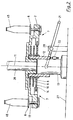
- the control device producing the rotation of the turntable 6 is shown schematically in FIG. 2.
- the turntable 2 is connected in terms of drive to the revolving center column 26, which is rotatably mounted in the bearing column 13 which is fixed on the machine table 27.
- the center column 26 extends into the area, not shown, below the machine table 27, where the drive motor and the corresponding force transmission elements are placed.
- a support body 12 On the lateral surface of the bearing column 13, a support body 12 is guided axially displaceably, which is secured against rotation by a tongue and groove connection, not shown.
- three control cams 8, 9 and 10 are axially offset in the direction of the turntable axis 11 parallel to the revolving plane of the turntable 2, i. H. rigidly attached to each other.
- the support body 12 can be axially moved by hand on a pivot lever 21 on the bearing column 13.
- the pivot lever 21 is rotatably fastened with its radially inner end to the support body 12 and articulated approximately in the center on a bearing pin 28 fixed to the frame.
- the height-related position of the support body 12 and thus of the control cams 8, 9 and 10 is determined by a stop body 22 fastened to the bearing column 13, on which the support body 12 is supported.
- the stop body 22 has an adjustable screw for each control cam, which forms the stop surface for the support body 12.
- the required stop surface can be brought into position by lifting the support body 12 by turning the stop body by rotating the stop body.
- each of the control cams 8, 9, 10 can, if necessary, be brought into the constant revolving plane of the control members 7 assigned to the turntables 6.
- the structure of the control elements 7 can be seen better in FIGS. 3 and 4.
- a control member 7 is shown viewed from the underside of the table.
- the cam roller 14, which scans the control cam 10 is rotatably attached to a displaceably mounted toothed rack which is aligned radially with respect to the rotary table axis 11 and at the end thereof which points towards the rotary table axis.
- the rack 15 see FIG. 4, is mounted in a sliding guide 29 fastened to the underside of the turntable 2, the toothing of the rack 15 reaching out through a lateral slot of the sliding guide 29 and cooperating with the toothing of a gear transmission 16.
- both the toothed rack 15 on the outside and the sliding guide 29 on the inside have a non-circular, preferably rectangular, cross section.
- the gear mechanism 16 comprises the gearwheel 30 fastened to the drive shaft 17 of the turntable 6 and the step gearwheel 31 which produces the frictional connection to the rack 15 and which has two toothings lying in one plane with different pitch circles, which have a translation between the rack 15 and the gearwheel 30 form.
- the step gear 31 is rotatably mounted on a bolt 32 fastened to the turntable 2.
- the cam roller 14 Since the control cam 10 shown in FIG. 3 has only one outer contour, the cam roller 14 must be pressed against the outer contour by spring force.
- the spring force is applied by a gas spring 18 integrated into the rack 15.
- a blind hole 33 In the end of the toothed rack 15 opposite the cam roller 14, a blind hole 33 extends into which a piston 34 sealingly engages, which is rigidly attached to the housing of the sliding guide 29.
- the ring line 36 has a connection, not shown, to a reservoir with below Gas under pressure. In operation, only leakage losses through the ring line 36 essentially have to be compensated for.
- connection between the reservoir and the ring line 36 is first interrupted by a corresponding valve and the ring line is opened to the atmosphere. Then the turntable 2 is completely rotated once by the machine drive when the vessel supply is blocked, so that all cam rollers 14 assume a common outer position in accordance with the maximum curve elevation and maintain this position due to the ventilation of the ring line 36 and the friction.
- All three control cams 8, 9, 10 have a matching maximum diameter. This enables a problem-free adjustment of the control cams, which is carried out by lifting the support body 12 by means of the swivel lever 21, rotating the stop body 22 and then lowering the support body 12 to the set stop surface. By reconnecting the ring line 36 to the reservoir containing compressed gas, all the cam rollers 14 are placed against the outer contour of the newly set control cam.
- the turntable 2 shown in Fig. 2 can be closed on its underside by a cover, not shown, so that no dirt can penetrate into the gear and an oil circulation lubrication can be used.
- the rotary table 6 mounted in the rotary table 2 is positively controlled by two contour surfaces per control curve.
- a spring element for pressing the cam rollers 14 as in the previously described exemplary embodiment can be dispensed with.
- the form-fitting control is particularly advantageous for equipment machines in the upper performance range due to the higher operational reliability.
- control cams 8, 9, 10 controlling the rotary movement of the turntable 6 are arranged fixedly below the orbit of the turntable 6.
- three different control cams 8, 9, 10 are arranged rigidly one below the other, i. H. they are not adjustable in height and secured against twisting.
- two cam rollers 14 fastened at a distance from one another to a carrier 37 are provided for each turntable, wherein the cam rollers 14 can be arranged in front or behind with respect to the pivot axis of the carrier 37.
- the distance between the two cam rollers 14 and the contours of a control cam is dimensioned such that all superimposed control cams 8, 9, 10 form an annular cavity which is at least slightly larger than the sliding sleeve 38 carrying the carrier 37 and the cam rollers 14, the axially displaceable but non-rotatably mounted on the intermediate shaft 39.
- The. Intermediate shaft 39 is rotatably mounted at a fixed height on the underside of the turntable and carries at its upper end a toothed segment 40 which meshes with the gearwheel 30 of the drive shaft 17 of the turntable 6.
- both are provided with a polygonal profile.
- the sliding sleeve 38 has at its upper end an annular groove in which a fork 41 engages, which in turn on one in Turntable housing rotatably mounted control shaft 42 is attached.
- the control shaft 42 carries at its end projecting radially outward from the housing of the turntable 2 a roller lever 43 with which the fork 41 can be used to move the cam rollers 14 into a region of the control cams 8, 9, 10 in which the contours of the Control curves 8, 9, 10 match, that is, they are aligned.
- This area expediently lies between the discharge conveyor 3 and the feed conveyor 1.
- a fixed, specifically controllable actuating device for adjusting the roller lever 43 can be arranged.
- a spring-loaded ball lock 44 is provided so that the roller lever 43 maintains its set position during one revolution.
Abstract
Description
Die Erfindung betrifft eine Ausstattungsmaschine zur Behandlung von Gefäßen gemäß dem Oberbegriff des Anspruchs 1.The invention relates to an equipment machine for treating vessels according to the preamble of
Es ist üblich, zum Aufbringen von Ausstattungsmaterial auf Gefäße diese auf einen Drehteller aufzuschieben, der an einem umlaufend angetriebenen Drehtisch einer Ausstattungsmaschine befestigt ist, wobei der drehbar auf dem Drehtisch gelagerter Drehteller mittels einer Kurvenrolle durch eine Nutkurve gesteuert wird, die üblicherweise unter dem Drehtisch feststehend angeordnet ist und ein bestimmtes, durch den Verlauf der Nutkurve festgelegtes Drehprogramm enthält. Speziell bei Formflaschen oder auch aufwendigen Ausstattungen, wie sie häufig bei Spirituosen vorkommen, sind verschiedene Drehprogramme, d.h. Nutkurven erforderlich, um spezielle Bewegungen bei der Übergabe des Ausstattungsmaterials und auch beim Anstreichen und/oder Andrücken ausführen zu können. So ist es beispielsweise bekannt, bei Gefäßen mit unterschiedlichen Durchmessern am Rumpf- und Halsbereich oder kegeliger Oberfläche im Moment der Etikettenübergabe eine der Drehrichtung des Drehtisches entgegengesetzte Drehung des Drehtellers auszuführen, während in anderen Fällen wiederum das Gefäß bei der Etikettenübergabe gleichsinnig in Umlaufrichtung des Drehtisches angetrieben wird, um möglichst lange Etiketten auf zylindrische Flächen übergeben zu können. Bei Standardausstattungen kann das Gefäß die Ubergabestation auch stillstehend passieren. Die Form des Gefäßes und die Ausstattung bestimmen auch den Verlauf der Anstreich- und Andrückstrecke nach der Ausstattungsstation. In diesem Bereich konnte man sich bisher dadurch behelfen, daß die Nutkurve für jede zu verarbeitende Gefäß- bzw. Ausstattungsart einen entsprechenden Abschnitt enthält, an dem die Anbürstkörper, Schwammrollen etc. plaziert werden, während die übrigen Abschnitte ungenutzt durchfahren werden. Diese Konstruktion hat den Nachteil, daß die erforderliche Nutkurve und damit der Drehtisch aufgrund des universellen Drehprogramms erheblich größer ausfallen, als bei einer für nur eine bestimmte Gefäß- bzw. Ausstattungsart ausgelegten Maschine.It is common to push equipment onto vessels on a rotary table that is attached to a rotating rotary table of an equipment machine, the rotary table rotatably mounted on the rotary table being controlled by means of a cam roller by a groove curve, which is usually fixed under the rotary table is arranged and contains a specific turning program determined by the course of the groove curve. Especially with molded bottles or complex equipment, as is often the case with spirits, various turning programs, ie grooved curves, are required in order to be able to perform special movements when transferring the equipment and also when painting and / or pressing. It is known, for example, to carry out a rotation of the turntable opposite to the direction of rotation of the turntable in the case of tubes with different diameters on the trunk and neck area or conical surface at the moment of label transfer, while in other cases the container is again driven in the same direction in the direction of rotation of the turntable during label transfer is passed to the longest possible labels on cylindrical surfaces to be able to. With standard equipment, the vessel can also pass the transfer station while it is stationary. The shape of the vessel and the equipment also determine the course of the painting and pressing section after the equipment station. In this area it has so far been possible to make use of the fact that the groove curve contains a corresponding section for each type of vessel or equipment to be processed, on which the brushing bodies, sponge rollers etc. are placed, while the other sections are passed through unused. This construction has the disadvantage that the required groove curve and thus the turntable turn out to be considerably larger than in the case of a machine designed for only one specific type of vessel or equipment because of the universal turning program.
Ferner ist durch die DE-A-33 23 919, die den Stand der Technik des Oberbegriffs des Anspruchs 1 bildet, bereits eine Konstruktion bekanntgeworden, bei der zur Steuerung eines Drehtellers zwei vollständige Nutkurven, die unterschiedliche Drehprogramme beinhalten können, unter dem Drehtisch vorgesehen sind. Nachteilig an dieser Ausführung ist die Tatsache, daß zur Umstellung von einem Drehprogramm auf das andere jeder Drehteller mit seiner einen Rollenhebel aufweisenden Steuereinrichtung einzeln von Hand vom Drehtisch gelöst, angehoben und in die zweite Nutkurve eingeführt werden muß. Eine schnelle Umrüstung einer Ausstattungsmaschine von einer Gefäß- bzw. Ausstattungsart auf eine davon abweichende andere Ausführung ist bei dieser Konstruktion kaum möglich, zumal die Nutkurven zur Vermeidung von Spiel sehr genau ausgeführt sind, so daß vor allem das Wiedereinführen der Kurvenrollen problematisch ist, wobei bei unsachgemäßer Handhabung die Nutkurve beschädigt werden kann. Zudem kann beim Abheben des Drehtellers vom Drehtisch auch Schmutz in die Nutkurve gelangen.Furthermore, from DE-A-33 23 919, which forms the prior art of the preamble of
Das DE-U-87 08 031.1 zeigt eine Maschine, deren Nutkurve mit steuerbaren Weichen ausgestattet ist, so daß die Kurvenrollen abschnittsweise verschiedene Äste der Nutkurve wahlweise durchfahren können. Als nachteilig an dieser Lösung wird die Verschleißanfälligkeit der Weichen und, bedingt durch die Fugen in der Nutkurve an dieser Stelle, der hohe Verschleiß der Kurvenrollen angesehen. Daneben kann es bei Versagen der Weichensteuerung zu erheblichen Beschädigungen sowohl der Nutkurven als auch der Drehtellersteuerung kommen.DE-U-87 08 031.1 shows a machine whose groove curve is equipped with controllable switches, so that the cam rollers can pass through different branches of the groove curve in sections. A disadvantage of this solution is the susceptibility to wear of the turnouts and, due to the joints in the groove curve at this point, the high wear of the cam rollers. In addition, if the turnout control fails, both the groove curves and the turntable control can be seriously damaged.
Zusätzlich ist bei beiden bekannten Vorrichtungen durch die nebeneinanderliegende Anordnung der Nutkurven der Gestaltungsfreiraum des Drehprogramms gegenüber einer Maschine mit nur einer Nutkurve naturgemäß durch den nur begrenzt vorhandenen Platz stark beschränkt. Der dem Rollenhebel maximal zur Verfügung stehende Schwenkwinkel kann bei zwei nebeneinanderliegenden Kurven nicht im gleichen Maße ausgenutzt werden, wie bei nur einer in etwa mittig liegenden Nutkurve.In addition, in the case of both known devices, the design freedom of the turning program compared to a machine with only one groove curve is naturally very limited due to the limited space available due to the adjacent arrangement of the groove curves. The maximum swivel angle available to the roller lever cannot be used to the same extent in two adjacent curves as in the case of only one roughly central groove curve.
Der Erfindung liegt die Aufgabe zugrunde, eine Ausstattungsmaschine zur Behandlung von Gefäßen mit unterschiedlicher Form und/oder Ausstattung zu schaffen, die eine bedienungsfreundliche Anpassung der Drehtellersteuerung bei einer Umstellung der Maschine von einer Gefäß- bzw. Ausstattungsart auf eine andere ermöglicht, wobei mehrere individuelle, voneinander unabhängig gestaltbare Drehprogramme zur Verfügung stehen sollen.The invention has for its object to provide an equipment machine for the treatment of vessels with different shapes and / or equipment, which enables a user-friendly adaptation of the turntable control when changing the machine from one type of vessel or equipment to another, several individual, turning programs that can be designed independently of one another should be available.
Diese Aufgabe wird durch die im kennzeichnenden Teil des Anspruchs 1 angegebenen Merkmale gelöst.This object is achieved by the features specified in the characterizing part of
Dadurch, daß die Steuerkurven in Richtung der Drehtischachse axial zueinander versetzt angeordnet sind, wobei die Steuerkurven und/oder das dem Drehteller zugeordnete Steuerglied relativ zueinander verstellbar sind, sind die Gestaltungsmöglichkeiten der einzelnen Steuerkurven unabhängig von den benachbarten weitgehend unbeschränkt. Darüber hinaus kann der dem Steuerglied des Drehtellers zur Verfügung stehende Bewegungsspielraum bei jeder einzelnen Steuerkurve voll ausgeschöpft werden, so daß kein zu großes Übersetzungsverhältnis zwischen der Kurvenrolle des Steuergliedes und der Drehtellerwelle gewählt werden muß. Damit kann das durch die Übersetzung vergrößerte, von der Steuerkurve herrührende Spiel am Drehteller in vertretbaren Grenzen gehalten werden.Characterized in that the control cams are arranged axially offset from one another in the direction of the turntable axis, the control cams and / or the control member assigned to the turntable being adjustable relative to one another, the design options of the individual control cams are largely unlimited, regardless of the neighboring ones. In addition, the range of motion available to the control member of the turntable can be fully exhausted with each individual control cam, so that it is not necessary to choose too large a transmission ratio between the cam roller of the control member and the turntable shaft. This means that the play on the turntable, which is increased by the translation and originates from the control cam, can be kept within reasonable limits.
Zur Umstellung von einer Gefäß- und/oder Ausstattungsform auf eine andere kann entweder das Steuerglied jedes Drehtellers in axialer Richtung verstellbar am Drehtisch befestigt sein, während die Steuerkurven feststehend ausgeführt sind oder umgekehrt. Die letztgenannte Möglichkeit erlaubt eine relativ einfache konstruktive Realisierung. Hierzu können die Steuerkurven unter dem Drehtisch parallel zu dessen Drehebene versetzt untereinander angeordnet werden, derart, daß wahlweise jede Steuerkurve in die Umlaufebene der Steuerglieder gebracht und in dieser Stellung arretiert werden kann. Besonders günstig ist eine gemeinsame Befestigung aller Steuerkurven auf einem einzigen Tragkörper, der axial zur Drehachse des Drehtisches verschiebbar gelagert ist. Eine besonders kompakte Bauweise ergibt sich, wenn die Steuerkurven jeweils in Form einer Scheibe ausgeführt sind, die eine definierte Außenkontur aufweist. Die Scheiben können an einem Tragkörper befestigt werden, der entlang der Lagersäule des Drehtisches verschiebbar gelagert und gegen Verdrehen beispielsweise durch eine Federnutverbindung gesichert ist.To change from one vessel and / or equipment form to another, either the control element of each turntable can be fastened to the turntable in an axially adjustable manner, while the control cams are designed to be stationary or vice versa. The latter possibility allows a relatively simple constructive implementation. For this purpose, the control cams can be arranged offset from one another under the turntable parallel to its rotary plane, in such a way that either control cams can optionally be brought into the circumferential plane of the control members and locked in this position. A common fastening of all control cams on a single support body, which is axially displaceable to the axis of rotation of the turntable, is particularly favorable. A particularly compact design results if the control cams are each designed in the form of a disk which has a defined outer contour. The panes can on be attached to a support body which is mounted displaceably along the bearing column of the turntable and is secured against rotation, for example by a spring groove connection.
Bei einer derartigen Ausführung können die den Drehtellern zugeordneten Steuerglieder fest an der Unterseite des Drehtisches gelagert werden. Die Steuerglieder müssen zur Umstellung des Drehprogramms in eine Position verbringbar sein, die ein Verschieben der Steuerkurven zuläßt. Hierzu sind alle technischen Elemente geeignet , die in der Lage sind die Steuerglieder außer Eingriff mit Steuerkurve zu bringen und sie nach erfolgter Verstellung der Steuerkurve wieder an diese anzulegen; wie z.B. pneumatische Zylinder. Besonders einfach läßt sich das beispielsweise dadurch erreichen, daß die Steuerkurven einen übereinstimmenden maximalen Außendurchmesser aufweisen und die Steuerglieder bei Erreichen dieser Stellung ihre Position anschließend beibehalten.In such an embodiment, the control members assigned to the turntables can be firmly mounted on the underside of the turntable. To change the turning program, the control elements must be able to be brought into a position which allows the control cams to be shifted. For this purpose, all technical elements are suitable, which are able to disengage the control members from the control curve and to put them back on after the control curve has been adjusted; such as. pneumatic cylinders. This can be achieved particularly easily, for example, in that the control cams have a matching maximum outer diameter and the control members then maintain their position when this position is reached.
Da bei der Verwendung einer Steuerkurve mit nur einer Außenkontur die Kurvenrolle des Steuergliedes durch ein Federelement gegen die Steuerkurve gedrückt wird, kann das Steuerglied bei Erreichen des maximalen Außendurchmessers der Steuerkurve beispielsweise mechanisch verriegelt werden. Wenn alle am Drehtisch befestigten Steuerglieder derart festgehalten werden, kann problemlos eine ein anderes Drehprogramm aufweisende Steuerkurve in die Umlaufebene der Steuerglieder gebracht werden. Durch Lösen der Verriegelung können sich die Kurvenrollen der Steuerglieder wiederum an die Steuerkurve anlegen. Auf eine spezielle Verriegelung kann dann verzichtet werden, wenn als Federelement zur Belastung der Kurvenrolle eine Gasfeder verwendet wird, die entlüftbar ist. Hierbei genügt es während eines Umlaufs des Drehtisches sämtliche Gasfedern zu entlüften, so daß die Steuerglieder mit ihren Kurvenrollen automatisch in der durch die Steuerkurve vorgegebenen maximalen Position stehen bleiben. Nach dem Verstellen der Steuerkurven können die Gasfedern zum Anlegen der Kurvenrollen an die Steuerkurve erneut mit Druck beaufschlagt werden. Besonders günstig ist die Verbindung aller Gasfedern durch eine Ringleitung, so daß ein einziger Anschluß zur Druckversorgung über einen Drehverteiler genügt.Since, when using a control curve with only one outer contour, the cam roller of the control element is pressed against the control curve by a spring element, the control element can be mechanically locked, for example, when the maximum outer diameter of the control curve is reached. If all the control elements attached to the turntable are held in this way, a control curve having a different rotation program can be brought into the rotating plane of the control elements without any problems. By releasing the lock, the cam rollers of the control elements can in turn attach themselves to the control cam. A special locking mechanism can be dispensed with if a gas spring that can be vented is used as the spring element for loading the cam roller. It is sufficient here during one circulation of the Vent all gas springs on the turntable so that the control members with their cam rollers automatically stop in the maximum position specified by the control cam. After adjusting the control cams, the gas springs can be pressurized again to apply the cam rollers to the control curve. The connection of all gas springs by means of a ring line is particularly favorable, so that a single connection for pressure supply via a rotary distributor is sufficient.
Das mittels einer Kurvenrolle die Steuerkurve abtastende Steuerglied des Drehtellers kann beispielsweise als Rollenhebel ausgebildet sein. Anstelle dessen kann die Kraftübertragung von der Kurvenrolle zur Drehtellerwelle auch über eine als Zahnstange ausgebildete Stößelstange mit einem die Hubbewegung in eine Drehbewegung umsetzenden Rädergetriebe erfolgen. Durch diese konstruktive Maßnahme können die Steuerkurven auch bei größeren, leistungsfähigen Maschinen relativ kompakt gestaltet werden, während der Abstand zur Drehtellerwelle durch entsprechend bemessene Stößelstangen überbrückt wird. Zusätzlich kann in bekannter Weise zwischen der Kurvenrolle und der Antriebswelle des Drehtellers eine den Anforderungen entsprechende Übersetzung erfolgen. Dies ist speziell bei Ausstattungsmaschinen für Gefäße mit hochwertiger Ausstattung häufig erforderlich, da bei diesen zu bearbeitenden Gefäßen oft eine bis über 360 Grad notwendige Drehung in beiden Richtungen des Drehtellers möglich sein muß. Der als Zahnstange ausgebildete Stößel kann auf einfache Weise an der Unterseite des Drehtisches radial zur Drehtischachse ausgerichtet befestigt sein und läuft mit diesem im Betrieb um. In die Zahnstange kann günstigerweise ein als Gaskammer dienender zylindrischer Hohlraum integriert sein, in den eine feststehende Kolbenstange eingreift, durch die mittels entsprechender Hohlbohrungen von außen über eine Ringleitung Druckgas zum Andrücken der Zahnstange und damit der Kurvenrolle gegen die Steuerkurve zugeleitet werden kann. Anstelle dessen wäre auch die Verwendung einer Spiralfeder möglich.The control member of the turntable which scans the control cam by means of a cam roller can be designed, for example, as a roller lever. Instead of this, the power transmission from the cam roller to the turntable shaft can also take place via a push rod designed as a toothed rack with a gear mechanism which converts the lifting movement into a rotating movement. This constructive measure allows the control cams to be made relatively compact even in the case of larger, more powerful machines, while the distance to the turntable shaft is bridged by appropriately dimensioned push rods. In addition, a translation corresponding to the requirements can take place in a known manner between the cam roller and the drive shaft of the turntable. This is often necessary especially in the case of equipment machines for vessels with high-quality equipment, since with these vessels to be processed it is often necessary to be able to rotate the turntable in both directions by more than 360 degrees. The tappet, which is designed as a toothed rack, can be attached in a simple manner to the underside of the turntable, oriented radially to the turntable axis, and rotates with it during operation. A cylindrical cavity serving as a gas chamber can be advantageously integrated into the toothed rack, into which a fixed piston rod engages, by means of the corresponding Hollow holes can be fed from the outside via a ring line of compressed gas for pressing the rack and thus the cam roller against the control cam. Instead of this, the use of a spiral spring would also be possible.
Ein noch größerer Gestaltungsfreiraum zur Ausführung der Steuerkurven ergibt sich, wenn die die Kurvenrolle belastende Gasfeder als doppelt wirkender Zylinder ausgebildet ist, wobei dieser im Normalbetrieb die Kurvenrolle gegen die Außenkontur einer Steuerkurve drückt und zum Umstellen die Kurvenrolle in eine zur Steuerkurve beliebig weit beabstandete Stellung bringen kann, so daß die Steuerkurven nicht unbedingt einen gemeinsamen, übereinstimmenden maximalen Außendurchmesser aufweisen müssen.An even greater freedom of design for the execution of the control curves is obtained if the gas spring loading the cam roller is designed as a double-acting cylinder, which presses the cam roller against the outer contour of a control curve in normal operation and brings the cam roller into a position that is spaced as far apart from the control curve as possible can, so that the control curves do not necessarily have to have a common, matching maximum outer diameter.
Der entlang der Lagersäule des Drehtisches verschiebbar geführte, die Steuerkurven aufnehmende Tragkörper kann durch einen am Maschinentisch angelenkten Schwenkhebel betätigt werden, wobei seine Stellung durch einen verstellbaren Anschlagkörper mit mehreren entsprechenden Anschlagflächen fixierbar ist.The support body, which is displaceably guided along the bearing column of the turntable and accommodates the control cams, can be actuated by a pivot lever which is articulated on the machine table, its position being fixable by an adjustable stop body having a plurality of corresponding stop surfaces.
Die Erfindung läßt sich darüber hinaus auch mit einer Zwangssteuerung für beide Drehrichtungen des Drehtellers, z.B. durch eine Steuerkurve mit zwei zusammenwirkenden Konturen, realisieren, so daß Federelemente zum Andrücken der Kurvenrollen gegen nur eine vorhandene Kurvenkontur entfallen können.The invention can also be with a positive control for both directions of rotation of the turntable, e.g. by means of a control curve with two interacting contours, so that spring elements for pressing the cam rollers against only one existing curve contour can be dispensed with.
Durch verwenden von zwei sich parallel mit ihrer Verzahnung gegenüberliegenden Zahnstangen pro Drehteller mit jeweils einer eigenen Kurvenrolle besteht die Möglichkeit Zwangslauf in beiden Drehrichtungen zu erzielen. Allerdings wären dann pro Drehprogramm zwei zusammengehörende, übereinanderliegende Steuerkurven erforderlich, deren Außenkonturen gegensätzlich ausgebildet sein müssen, derart, daß die beiden, jeweils mit einer Steuerkurve zusammenwirkenden Zahnstangen eine gegensinnige Schubbewegung ausführen, die durch ein zwischen den beiden Zahnstangen angeordnetes, in deren Verzahnung eingreifendes Zahnrad in eine Drehbewegung umgesetzt wird. Das Zahnrad kann direkt an der Drehtellerantriebswelle befestigt sein.By using two toothed racks opposite each other in parallel with their toothing, each with its own cam roller, it is possible to achieve positive rotation in both directions of rotation. However, two rotating superimposed programs would belong to each turning program Control cams are required, the outer contours of which must be of opposite design, such that the two racks, each of which cooperates with a control cam, perform an opposite thrust movement, which is converted into a rotary movement by a gear arranged between the two racks and engaging in their teeth. The gear can be attached directly to the turntable drive shaft.
Bei der beschriebenen Ausführung werden die Steuerkurven zweckmäßigerweise starr befestigt, die Steuerglieder, d. h. die Kurvenrollen, dagegen verstellbar. Hierzu besitzen die Steuerkurven einen übereinstimmenden Bereich, günstigerweise zwischen Gefäßaus- und -einlauf, in dem die übereinanderliegenden Außenkonturen und die Kurvenrollen fluchten, so daß beim Durchfahren dieses Abschnittes die Kurvenrollen relativ zu den Steuerkurven verschoben werden können.In the described embodiment, the control curves are expediently rigidly attached, the control elements, i. H. the cam rollers, however adjustable. For this purpose, the control cams have a corresponding area, advantageously between the vessel outlet and inlet, in which the superimposed outer contours and the cam rollers are aligned, so that the cam rollers can be displaced relative to the control cams when passing through this section.
Das Verschieben der Kurvenrollen kann beispielsweise durch ein am Drehtischumfang ortsfest angeordnetes, steuerbares Kurvenstück in der Umlaufebene der Kurvenrollen vorgenommen werden. Damit können die Steuerglieder bei laufender Maschine auch beliebig wahlweise verschiedenen Steuerkurven zugeordnet werden, womit die gleichzeitige Verarbeitung von Gefäßen mit verschiedenen Ausstattungen in einer Ausstattungsmaschine möglich wird.The cam rollers can be moved, for example, by means of a controllable cam piece arranged in a fixed manner on the circumference of the turntable in the circumferential plane of the cam rollers. This means that the control elements can be optionally assigned to different control curves while the machine is running, which enables the simultaneous processing of vessels with different equipment in one equipment machine.
Bei Ausstattungsmaschinen mit einer hohen Anzahl von Drehtellern und damit zwangsläufig großem Drehtischdurchmesser ist es dagegen günstiger, die Steuerkurven unmittelbar unterhalb des Umlaufbereiches der Drehteller anzuordnen. Es besteht grundsätzlich wiederum die Möglichkeit, eine Steuerkurve mit nur einer Kontur pro Drehprogramm entweder auf der radial inneren oder der radial äußeren Seite der Umlaufbahn der Kurvenrollen anzuordnen und diese mittels eines Federelements kraftschlüssig anzulegen, oder eine Steuerkurve mit zwei Konturen pro Drehprogramm zum formschlüssigen Führen der Kurvenrollen vorzusehen.In the case of equipment machines with a large number of turntables and thus inevitably large turntable diameters, on the other hand, it is cheaper to arrange the control cams directly below the rotating area of the turntables. In principle, there is again the possibility of creating a control curve with only one contour per turning program either on the radially inner one or to arrange the radially outer side of the orbit of the cam rollers and to apply them non-positively by means of a spring element, or to provide a control cam with two contours per turning program for the positive guidance of the cam rollers.
Die letztgenannte Möglichkeit läßt sich auf einfache Weise mit feststehenden, übereinanderliegenden Steuerkurven und verstellbaren Steuergliedern realisieren, wobei die Steuerkurven einen übereinstimmenden Bereich umfassen, in dem die Steuerglieder bzw. die Kurvenrollen in der vorhergehend beschriebenen Weise verschoben werden können.The latter possibility can be realized in a simple manner with fixed control cams lying one above the other and adjustable control members, the control cams comprising a corresponding area in which the control members or the cam rollers can be moved in the manner described above.
Damit trotz der verschiedenartigen Kurvenverläufe eine Kraftübertragung zur Drehtellerantriebswelle erfolgen kann, weisen die an beiden Seiten der Umlaufbahn angeordneten Konturen der Steuerkurven einen ausreichend großen Abstand auf, der so bemessen ist, daß die Drehtellerantriebswellen bzw. die die Kurvenrollen tragenden Wellen während eines gesamten Umlaufes kollisionsfrei bis zur untersten Steuerkurve durch einen gemeinsamen ringförmigen Hohlraum hindurchgreifen können. Zum gleichzeitigen Abtasten der beidseitig der Umlaufbahn verlaufenden Konturen der Steuerkurven sind pro Drehteller zwei an einem Träger mit Abstand zueinander befestigte Kurvenrollen zweckmäßig. Dieser Träger ist schwenkbar gelagert und mit der Drehtellerantriebswelle antriebsmäßig verbunden. Zum Einstellen eines anderen Drehprogrammes kann der Träger relativ zu den Steuerkurven verschoben werden.So that a power transmission to the turntable drive shaft can take place in spite of the different types of curves, the contours of the control cams arranged on both sides of the orbit are sufficiently large that the turntable drive shafts or the shafts carrying the cam rollers are collision-free during an entire revolution can reach through to the lowest control curve through a common annular cavity. For simultaneous scanning of the contours of the control curves running on both sides of the orbit, two cam rollers attached to a carrier at a distance from one another are expedient for each turntable. This carrier is pivotally mounted and drivingly connected to the turntable drive shaft. To set a different turning program, the carrier can be moved relative to the control cams.
Im Nachstehenden werden zwei Ausführungsbeispiele anhand der Figuren beschrieben.Two exemplary embodiments are described below with reference to the figures.
Es zeigen:
- Fig. 1
- eine Draufsicht auf eine Ausstattungsmaschine ohne deren Oberteil,
- Fig. 2
- einen senkrechten Schnitt durch einen Drehtisch,
- Fig. 3
- einen von der Unterseite des Drehtisches aus dargestellten Drehtellerantrieb,
- Fig. 4
- einen Schnitt durch den in Fig. 3 dargestellten Drehtellerantrieb,
- Fig. 5
- einen senkrechten Schnitt durch einen Teil eines Drehtisches nach einem zweiten Ausführungsbeispiel und
- Fig. 6
- einen horizontalen Schnitt durch einen Drehtisch nach Fig 5.
- Fig. 1
- a plan view of an equipment machine without the upper part,
- Fig. 2
- a vertical section through a turntable,
- Fig. 3
- a turntable drive shown from the underside of the turntable,
- Fig. 4
- 3 shows a section through the turntable drive shown in FIG. 3,
- Fig. 5
- a vertical section through part of a turntable according to a second embodiment and
- Fig. 6
- a horizontal section through a turntable according to FIG. 5.
Wie in Fig. 1 gut zu erkennen ist, werden die von einem Förderband angelieferten auszustattenden Gefäße 45 zunächst auf die Maschinenteilung auseinander gezogen und durch einen als umlaufenden Stern ausgebildeten Zuförderer 1 stellungsgerecht auf einen Drehteller 6 tragenden Drehtisch 2 aufgeschoben. Noch bevor ein einlaufendes Gefäß 45 durch den Zuförderer 1 frei gegeben wird, erfolgt ein axiales Einspannes des Gefäßes zwischen dem den Gefäßboden aufnehmenden Drehteller 6 und einer durch eine Kurve gesteuerte, sich von oben auf den Gefäßkopf absenkende Zentrierglocke. Die Zentrierglocken sind hierzu üblicherweise stellungsgerecht zu den Drehtellern an einem synchron zum Drehtisch umlaufenden, in Fig. 1 nicht dargestellten, Oberteil befestigt. Unmittelbar danach erhält das Gefäß durch eine erste Ausstattungsstation 23 beispielsweise ein Rumpfetikett und eine Stanniolfolie für den Flaschenhals. Danach durchläuft das Gefäß einen Anbürst- und Anrollkanal, mit feststehenden Bürsten 4 und Schwammrollen 5, die austauschbar am Umfang des Drehtisches 2 angeordnet sind. Diese Anstreich- und Andrückelemente werden ebenso wie Führungsbögen und andere Teile der Maschine bei Gefäßumstellungen oder einem Wechsel der Ausstattung ausgetauscht, d. h. diese Elemente werden individuell zusammengestellt. Demensprechend angepaßte Drehprogramme für den Drehteller 6 müssen in diesem Bereich zur Verfügung stehen. Danach kann beispielsweise noch ein Rückenetikett an einer zweiten Ausstattungsstation 24 übergeben werden, das wiederum auf dem Wege bis zum Abförderer 3 durch Bürsten 4 und Schwammrollen 5 angestrichen bzw. angedrückt werden kann. Durch einen mit einem Führungsbogen 25 zusammenwirkenden Abförderer 3 wird das Gefäß vom Drehtisch 2 auf ein Abförderband abgegeben, wobei während dieses Vorganges noch eine Endbehandlung der Stanniolfolie durch rotierende Bürsten etc. erfolgen kann.As can be clearly seen in FIG. 1, the
Die die Drehung des Drehtellers 6 erzeugende Steuereinrichtung ist in der Fig. 2 schematisch dargestellt. Der Drehtisch 2 ist antriebsmäßig mit der umlaufend angetriebenen Mittelsäule 26 verbunden, die drehbar in der auf dem Maschinentisch 27 feststehend befestigten Lagersäule 13 gelagert ist. Die Mittelsäule 26 erstreckt sich bis in den nicht näher dargestellten Bereich unter dem Maschinentisch 27, wo der Antriebsmotor und die entsprechenden Kraftübertragungselemente plaziert sind.The control device producing the rotation of the
Auf der Mantelfläche der Lagersäule 13 ist axial verschiebbar ein Tragkörper 12 geführt, der durch eine nicht dargestellte Feder-Nut-Verbindung gegen Verdrehen gesichert ist. An dem Tragkörper 12 sind parallel zur Umlaufebene des Drehtisches 2 drei Steuerkurven 8, 9 und 10 in Richtung der Drehtischachse 11 axial versetzt, d. h. untereinander starr befestigt. Ferner kann der Tragkörper 12 durch einen Schwenkhebel 21 axial auf der Lagersäule 13 von Hand verschoben werden. Hierzu ist der Schwenkhebel 21 mit seinem radial inneren Ende drehbar am Tragkörper 12 befestigt, und in etwa mittig an einem gestellfesten Lagerbolzen 28 angelenkt. Die höhenmäßige Position des Tragkörpers 12 und damit der Steuerkurven 8, 9 und 10 wird durch einen an der Lagersäule 13 befestigten Anschlagkörper 22 festgelegt, auf den sich der Tragkörper 12 abstützt. Der Anschlagkörper 22 besitzt für jede Steuerkurve jeweils eine einstellbare Schraube, die die Anschlagfläche für den Tragkörper 12 bildet. Die erforderliche Anschlagfläche kann nach dem Anheben des Tragkörpers 12 mittels des Schwenkhebels 21 durch drehen des Anschlagkörpers in Position gebracht werden. Dadurch kann jede der Steuerkurven 8, 9, 10 bei Bedarf in die gleichbleibende Umlaufebene der den Drehtellern 6 zugeordneten Steuerglieder 7 gebracht werden. Der Aufbau der Steuerglieder 7 ist besser in den Fig. 3 und 4 erkennbar.On the lateral surface of the
In Fig. 3 wird ein Steuerglied 7 von der Tischunterseite aus betrachtet dargestellt. Die die Steuerkurve 10 abtastende Kurvenrolle 14 ist drehbar an einer radial zur Drehtischachse 11 ausgerichteten, verschiebbar gelagerten Zahnstange, an deren zur Drehtischachse hinweisenden Ende, befestigt.In Fig. 3, a
Die Zahnstange 15 ist, siehe Fig. 4, in einer an der Unterseite des Drehtisches 2 befestigten Schiebeführung 29 gelagert, wobei die Verzahnung der Zahnstange 15 durch einen seitlichen Schlitz der Schiebeführung 29 nach außen hindurchgreift und mit der Verzahnung eines Rädergetriebes 16 zusammenwirkt. Um einen exakten Eingriff der Verzahnungen zu gewährleisten, weisen sowohl die Zahnstange 15 an ihrer Außenseite als auch die Schiebeführung 29 innen einen unrunden, vorzugsweise rechteckigen, Querschnitt auf. Das Rädergetriebe 16 umfaßt das an der Antriebswelle 17 des Drehtellers 6 befestigte Zahnrad 30 und das den Kraftschluß, zur Zahnstange 15 herstellende Stufenzahnrad 31, das zwei in einer Ebene liegende Verzahnungen mit unterschiedlichen Teilkreisen besitzt, die eine Übersetzung zwischen der Zahnstange 15 und dem Zahnrad 30 bilden. Hierzu ist das Stufenzahnrad 31 drehbar auf einem am Drehtisch 2 befestigten Bolzen 32 gelagert.The
Da die in Fig. 3 zu erkennende Steuerkurve 10 nur eine Außenkontur besitzt, muß die Kurvenrolle 14 durch Federkraft an die Außenkontur angedrückt werden. Beim Ausführungsbeispiel wird die Federkraft durch eine in die Zahnstange 15 integrierte Gasfeder 18 aufgebracht. In das der Kurvenrolle 14 gegenüberliegende Ende der Zahnstange 15 erstreckt sich eine Sacklochbohrung 33 in die ein Kolben 34 abdichtend eingreift, der starr am Gehäuse der Schiebeführung 29 befestigt ist. Durch die Durchgangsbohrung 35 im Kolben 34 besteht ein Verbindungskanal zwischen der alle benachbarten Kolben verbindenden Ringleitung 36 und dem durch die Sacklochbohrung 33 und dem Boden des Kolbens 34 gebildeten Hohlraum in der Zahnstange 15. Die Ringleitung 36 besitzt einen nicht dargestellten Anschlup an ein Reservoir mit unter Überdruck stehendem Gas. Im Betrieb müssen im wesentlichen nur Leckverluste durch die Ringleitung 36 ausgeglichen werden.Since the
Soll die Ausstattungsmaschine auf ein anderes Drehprogramm umgestellt werden, so wird zunächst die Verbindung zwischen dem Reservoir und der Ringleitung 36 durch ein entsprechendes Ventil unterbrochen und die Ringleitung zur Atmosphäre geöffnet. Danach wird der Drehtisch 2 bei gesperrter Gefäßzufuhr einmal vollständig durch den Maschinenantrieb gedreht, so daß alle Kurvenrollen 14 entsprechend der maximalen Kurvenerhebung eine gemeinsame äußere Position einnehmen und aufgrund der Entlüftung der Ringleitung 36 und der Reibung diese Stellung beibehalten.If the equipment machine is to be changed over to a different turning program, the connection between the reservoir and the
Alle drei Steuerkurven 8, 9, 10 besitzen einen übereinstimmenden maximalen Durchmesser. Dadurch ist eine problemlose Verstellung der Steuerkurven möglich, die durch Anheben des Tragkörpers- 12 mittels des Schwenkhebels 21, Verdrehen des Anschlagkörpers 22 und nachfolgendes Absenken des Tragkörpers 12 auf die eingestellte Anschlagfläche erfolgt. Durch erneutes Verbinden der Ringleitung 36 mit dem Druckgas enthaltenden Reservoir werden sämtliche Kurvenrollen 14 gegen die Außenkontur der neu eingestellten Steuerkurve angelegt.All three
Der in Fig. 2 dargestellte Drehtisch 2 kann an seiner Unterseite durch einen nicht dargestellten Deckel geschlossen sein, so daß kein Schmutz in die Getriebe eindringen und eine Ölumlaufschmierung eingesetzt werden kann.The
Bei dem in den Fig. 5 und 6 dargestellten zweiten Ausführungsbeispiel wird der im Drehtisch 2 gelagerte Drehteller 6 durch zwei Konturflächen pro Steuerkurve formschlüssig zwangsgesteuert. Dadurch kann auf ein Federelement wie beim vorhergehend beschriebenen Ausführungsbeispiel zum Andrücken der Kurvenrollen 14 verzichtet werden. Die formschlüssige Steuerung ist besonders bei Ausstattungsmaschinen im oberen Leistungsbereich aufgrund der höheren Betriebssicherheit von Vorteil.In the second exemplary embodiment shown in FIGS. 5 and 6, the rotary table 6 mounted in the rotary table 2 is positively controlled by two contour surfaces per control curve. As a result, a spring element for pressing the
Ähnlich wie bei einer konventionellen Etikettiermaschine sind die die Drehbewegung des Drehtellers 6 steuernden Steuerkurven 8, 9, 10 unterhalb der Umlaufbahn der Drehteller 6 feststehend angeordnet. Allerdings sind beim Ausführungsbeispiel nach Fig. 5 gleich drei verschiedene Steuerkurven 8, 9, 10 untereinander starr angeordnet, d. h. sie sind nicht höhenverstellbar und gegen Verdrehen gesichert. Im Gegensatz zu herkömmlichen Maschinen sind jedoch pro Drehteller jeweils zwei mit Abstand zueinander an einem Träger 37 befestigte Kurvenrollen 14 vorgesehen, wobei die Kurvenrollen 14 in Bezug auf die Schwenkachse des Trägers 37 vor- oder nachlaufend angeordnet sein können.Similar to a conventional labeling machine, the
Der Abstand der beiden Kurvenrollen 14 und der anliegenden Konturen einer Steuerkurve ist so bemessen, daß alle übereinanderliegenden Steuerkurven 8, 9, 10 einen ringförmigen Hohlraum bilden, der mindestens etwas größer ist, als die den Träger 37 und die Kurvenrollen 14 tragende Schiebehülse 38, die axial verschiebbar, aber verdrehfest auf der Zwischenwelle 39 gelagert ist. Die. Zwischenwelle 39 ist höhenfest an der Unterseite des Drehtisches drehbar gelagert und trägt an ihrem oberen Ende ein Zahnsegment 40, das mit dem Zahnrad 30 der Antriebswelle 17 des Drehtellers 6 kämmt. Zur Drehmomentübertragung von der Schiebehülse 38 zur Zwischenwelle 39 sind beide mit einem Polygonprofil versehen.The distance between the two
Die Schiebehülse 38 besitzt an ihrem oberen Ende eine Ringnut, in die eine Gabel 41 eingreift, die wiederum an einer im Drehtischgehäuse verdrehbar gelagerten Steuerwelle 42 befestigt ist. Die Steuerwelle 42 trägt an ihrem radial nach außen aus dem Gehäuse des Drehtisches 2 herausragendem Ende einen Rollenhebel 43, mit dem mittels der Gabel 41 ein Verschieben der Kurvenrollen 14 in einen Bereich der Steuerkurven 8, 9, 10 möglich ist, in dem die Konturen der Steuerkurven 8, 9, 10 übereinstimmen, d. h. miteinander fluchten. Dieser Bereich liegt zweckmäßigerweise zwischen dem Abförderer 3 und dem Zuförderer 1. Hier kann eine feststehende, gezielt steuerbare Betätigungseinrichtung zum Verstellen des Rollenhebels 43 angeordnet sein. Damit der Rollenhebel 43 während eines Umlaufes seine eingestellte Position beibehält, ist eine federbelastete Kugelarretierung 44 vorgesehen.The sliding
Claims (26)
- Fitting machine for the treatment of vessels of different shape and/or with different fitting, in particular bottles, with an input conveyor, a rotationally drivable turntable with at least one fitting station arranged at the circumference thereof with subsequent brush-on and press-on elements and an output conveyor, wherein the turntable comprises at least one rotatably mounted revolving plate with an associated control member which cooperates with a non-rotatably mounted control cam and wherein at least two differnt control cams (8, 9, 10) are provided, each comprising a complete revolving programme for the revolving plate (6), for one revolution of the turntable (2), characterisedin that the control cams (8, 9, 10) are axially offset in the direction of the turntable axis (11) and in that, for conversion from one form of vessel and/or fitting to another, the control member (7) associated with the revolving plate (6) and/or the control cams (8, 9, 10) are displaceable relative to each other.
- Apparatus according to claim 1, characterised in that the control cams (8, 9, 10) are arranged one below the other under the turntable (2), offset and parallel to the plane of rotation thereof.
- Apparatus according to claim 1 or 2, characterised in that each control cam (8, 9, 10) can be brought into the plane of rotation of the control members (7) selectively and locked in this position.
- Apparatus according to any of claims 1 to 3, characterised in that the control cams (8, 9, 10) are mounted axially slidably relative to the turntable axis (11).
- Apparatus according to any of claims 1 to 4, characterised in that the control cams (8, 9, 10) are mounted jointly on a supporting body (12).
- Apparatus according to any of claims 1 to 5, characterised in that the control cams (8, 9, 10) are arranged on the radially inner side of the path of rotation of the control members (7).
- Apparatus according to claim 5 or 6, characterised in that the supporting body (12) is mounted slidably on the bearing column (13) of the turntable (2).
- Apparatus according to any of claims 1 to 7, characterised in that the control cams (8, 9, 10) are in each case constructed as a disc with a predefined outer contour.
- Apparatus according to any of claims 1 to 8, characterised in that the control cams (8, 9, 10) have a corresponding maximum outside diameter.
- Apparatus according to any of claims 1 to 9, characterised in that the control member (7) includes a cam roller (14) and a transmission mechanism.
- Apparatus according to claim 10, characterised in that the transmission mechanism comprises a rack (15) which is guided on the lower side of the turntable (2) and aligned radially with the turntable axis (11) and which carries a cam roller (14) at its end directed towards the centre.
- Apparatus according to claim 11, characterised in that the rack (15) acts via a gear mechanism (16) on the drive shaft (17) of the revolving plate (6).
- Apparatus according to any of claims 10 to 12, characterised in that the cam roller (14) is biased by means of a spring element against the outer contour of the associated control cam (8, 9, 10).
- Apparatus according to claim 13, characterised in that the spring element is constructed as a flat spiral spring.
- Apparatus according to claim 13, characterised in that the spring element is constructed as a gas spring (18).
- Apparatus according to claim 15, characterised in that the gas springs (18) are connected to each other by a ring pipe (36) which can be connected to a pressurised reservoir.
- Apparatus according to claim 16, characterised in that the ring pipe (36) can be evacuated.
- Apparatus according to any of claims 8 to 17, characterised in that the outer contour of all the control cams (8, 9, 10) reaches its maximum corresponding distance from the turntable axis (11) preferably in the region between bottle outlet and inlet.
- Apparatus according to any of claims 10 to 18, characterised in that the cam rollers (14) can be locked at their maximum distance from the turntable axis (11).
- Apparatus according to claims 15 and 16, characterised in that the gas spring (18) is constructed as a double-acting cylinder, wherein the latter during normal operation biases the cam roller (14) against the outer contour of a control cam (8, 9, 10) and for conversion moves the cam roller (14) into a position at a distance from the control cam (8, 9, 10).
- Apparatus according to claim 7, characterised in that the position of the supporting body (12) can be adjusted by a pivot lever (21) linked to the machine table (27) and fixed by an adjustable stop body (22) with corresponding stop faces.
- Apparatus according to any of claims 1 to 4, characterised in that the control members (7), or at least the parts thereof cooperating with the control cam (8, 9, 10), for conversion can be brought out of contact with the control cam (8, 9, 10).
- Apparatus according to either of claims 1 or 2, characterised in that the control cams (8, 9, 10) are arranged stationarily in the region of rotation of the cam rollers (14).
- Apparatus according to claim 23, characterised in that the control cams (8, 9, 10) have a common section with corresponding cam shape, in which the contours of the control cams (8, 9, 10) are aligned.
- Apparatus according to any of claims 1, 2, 23 or 24, characterised in that the control members (7) or at least the cam rollers (14) thereof are mounted on the turntable (2) for displacement relative to the control cams (8, 9, 10).
- Apparatus according to claim 24 or 25, characterised in that displacement of the cam rollers (14) takes place by a controllable actuating device placed on the section with corresponding cam shape.
Applications Claiming Priority (3)
| Application Number | Priority Date | Filing Date | Title |
|---|---|---|---|
| DE4009642 | 1990-03-26 | ||
| DE4009642A DE4009642C1 (en) | 1990-03-26 | 1990-03-26 | |
| PCT/EP1991/000438 WO1991014625A1 (en) | 1990-03-26 | 1991-03-08 | Equipping machine for treating vessels |
Publications (2)
| Publication Number | Publication Date |
|---|---|
| EP0521930A1 EP0521930A1 (en) | 1993-01-13 |
| EP0521930B1 true EP0521930B1 (en) | 1994-07-20 |
Family
ID=6403063
Family Applications (1)
| Application Number | Title | Priority Date | Filing Date |
|---|---|---|---|
| EP91906306A Expired - Lifetime EP0521930B1 (en) | 1990-03-26 | 1991-03-08 | Equipping machine for treating vessels |
Country Status (8)
| Country | Link |
|---|---|
| US (1) | US5326422A (en) |
| EP (1) | EP0521930B1 (en) |
| JP (1) | JP2547291B2 (en) |
| CN (1) | CN1023889C (en) |
| CA (1) | CA2067799A1 (en) |
| DE (1) | DE4009642C1 (en) |
| ES (1) | ES2057879T3 (en) |
| WO (1) | WO1991014625A1 (en) |
Families Citing this family (18)
| Publication number | Priority date | Publication date | Assignee | Title |
|---|---|---|---|---|
| IT1270500B (en) * | 1993-04-09 | 1997-05-06 | Alfa Costr Mecc Spa | DEVICE FOR CHANGING THE TIMING IN THE ROTATING KINEMATIC CONNECTION BETWEEN CAROUSEL AND LABELING GROUP IN A LABELING MACHINE. |
| US5858143A (en) * | 1993-09-16 | 1999-01-12 | B & H Manufacturing, Inc. | Computer controlled labeling machine for applying labels including stretch labels and tactilely sensible indicia on articles |
| US5478422A (en) * | 1993-09-16 | 1995-12-26 | B & H Manufacturing Company, Inc. | Computer controlled turret type labeling machine |
| DE19513064B4 (en) * | 1995-04-07 | 2004-04-01 | Khs Maschinen- Und Anlagenbau Ag | Method and system for filling containers with a liquid filling material and filling machine and labeling device for use in this method or system |
| DE19746765C2 (en) * | 1997-10-23 | 2000-08-24 | Fribosa Ag Werkzeug Und Maschi | Labeling station for objects, in particular bottles, with removal elements for the labels, which are driven in rotation via a cam mechanism |
| FR2783235B1 (en) | 1998-09-14 | 2000-11-10 | Prot Decoration Conditionnemen | MACHINE FOR LAYING LABEL SLEEVES ON BOTTLES |
| US6272949B1 (en) * | 1998-12-23 | 2001-08-14 | Amsted Industries Incorporated | Air operated fifth wheel uncoupling apparatus |
| US6263940B1 (en) | 1999-04-21 | 2001-07-24 | Axon Corporation | In-line continuous feed sleeve labeling machine and method |
| US6398006B1 (en) * | 2000-08-29 | 2002-06-04 | Joseph E. Seagram & Sons Ltd. | Rotary turret with pedestals and a method of controlling rotation thereof |
| WO2002098742A2 (en) * | 2001-06-01 | 2002-12-12 | Interactive Packaging Group, Ltd. | Method, machine and object for placement of multiple labels |
| ITBO20020633A1 (en) * | 2002-10-08 | 2004-04-09 | Azionaria Costruzioni Acma Spa | METHOD AND MACHINE FOR DISPENSING FLUID SUBSTANCES INSIDE CONTAINERS |
| ITVI20030035A1 (en) * | 2003-02-20 | 2004-08-21 | Clever Srl | AUTOMATIC MACHINE FOR THE APPLICATION OF LABELS ON CONTAINERS. |
| DE10357329A1 (en) * | 2003-12-05 | 2005-07-21 | Khs Maschinen- Und Anlagenbau Ag | Labeling machine with brush bodies |
| DE202004021791U1 (en) * | 2004-05-29 | 2011-02-10 | Krones Ag | Machine for aligning and equipping objects |
| ITPR20050031A1 (en) * | 2005-06-20 | 2006-12-21 | Sig Simonazzi Spa | DEVICE FOR ROTATION OF PLATES TAKES CONTAINERS IN A MACHINE LABELING MACHINE. |
| DE102009033810A1 (en) | 2009-07-18 | 2011-01-27 | Till, Volker, Dipl.-Ing. | Plant for printing on containers |
| DE102009058084A1 (en) * | 2009-12-14 | 2011-06-16 | Krones Ag | Device and method for transporting containers with floor guide |
| IT202100020531A1 (en) * | 2021-07-30 | 2023-01-30 | Antares Vision S P A | CAROUSEL FOR HANDLING CONTAINERS IN INSPECTION MACHINES |
Family Cites Families (5)
| Publication number | Priority date | Publication date | Assignee | Title |
|---|---|---|---|---|
| FR2259173B1 (en) * | 1974-01-28 | 1977-03-04 | Amigues Lucien | |
| DE3323919C2 (en) * | 1983-07-02 | 1986-08-21 | Jagenberg AG, 4000 Düsseldorf | Carrier for bottle turntables |
| DE3622179A1 (en) * | 1986-07-02 | 1988-01-14 | Jagenberg Ag | Labelling machine, especially for the all-round labelling of articles, such as bottles |
| DE8708031U1 (en) * | 1987-06-05 | 1988-03-03 | Krones Ag Hermann Kronseder Maschinenfabrik, 8402 Neutraubling, De | |
| DE3735882C1 (en) * | 1987-10-23 | 1988-12-01 | Eti Tec Maschb Gmbh | Drive for a turntable in a labeling machine for bottles |
-
1990
- 1990-03-26 DE DE4009642A patent/DE4009642C1/de not_active Expired - Lifetime
-
1991
- 1991-03-08 JP JP3505702A patent/JP2547291B2/en not_active Expired - Fee Related
- 1991-03-08 US US07/927,285 patent/US5326422A/en not_active Expired - Fee Related
- 1991-03-08 EP EP91906306A patent/EP0521930B1/en not_active Expired - Lifetime
- 1991-03-08 WO PCT/EP1991/000438 patent/WO1991014625A1/en active IP Right Grant
- 1991-03-08 ES ES91906306T patent/ES2057879T3/en not_active Expired - Lifetime
- 1991-03-08 CA CA002067799A patent/CA2067799A1/en not_active Abandoned
- 1991-03-25 CN CN91101865.4A patent/CN1023889C/en not_active Expired - Fee Related
Also Published As
| Publication number | Publication date |
|---|---|
| ES2057879T3 (en) | 1994-10-16 |
| US5326422A (en) | 1994-07-05 |
| CA2067799A1 (en) | 1991-09-27 |
| JP2547291B2 (en) | 1996-10-23 |
| JPH05505583A (en) | 1993-08-19 |
| EP0521930A1 (en) | 1993-01-13 |
| CN1055155A (en) | 1991-10-09 |
| WO1991014625A1 (en) | 1991-10-03 |
| DE4009642C1 (en) | 1991-08-29 |
| CN1023889C (en) | 1994-03-02 |
Similar Documents
| Publication | Publication Date | Title |
|---|---|---|
| EP0521930B1 (en) | Equipping machine for treating vessels | |
| DE3050382C1 (en) | Labeling machine for objects, especially bottles | |
| DE2255582A1 (en) | DEVICE FOR PRINTING TUBE-SHAPED OBJECTS | |
| DE10145455A1 (en) | Machine for furnishing articles | |
| DE2858262C2 (en) | Device for mounting the mandrel carrier on a printing machine for cylindrical containers | |
| EP0544176A1 (en) | Multicolour pad printing machine | |
| EP2387535A2 (en) | Container treatment machine | |
| DE2022842B2 (en) | Device for printing the surfaces of cylindrical or frustoconical objects | |
| EP0146096B1 (en) | Lifting-turntable device | |
| DE2733855C3 (en) | Attachment device for a capping machine for rolling closure caps on containers | |
| DE2623818A1 (en) | TURNTABLE FOR A LABELING MACHINE | |
| DE3915489C1 (en) | ||
| DE4022486C1 (en) | Bottle reverser or inverter - uses gripping head opened and closed by first cam and swivelled by second cam | |
| DE1561003B1 (en) | Device for the continuous printing of spiked, cylindrical containers | |
| DE3622179C2 (en) | ||
| DE3933804C2 (en) | ||
| DE7230785U (en) | DETACHABLE HEAD SET FOR THE SEALING HEAD OF A SEALING MACHINE | |
| EP0195378B1 (en) | Printing device | |
| DE3507224A1 (en) | Assembly device | |
| DE19821253B4 (en) | labeling | |
| CH681955A5 (en) | ||
| EP0485568B1 (en) | Labelling machine for vessels | |
| DE3925842A1 (en) | Processing machine for bottles - has two independently controllable centring devices to hold bottles during their path through machine | |
| EP0879646A2 (en) | Apparatus for applying a fluid on a surface along a curved path | |
| DE19538943C2 (en) | Container labeling device with swiveled pallets |
Legal Events
| Date | Code | Title | Description |
|---|---|---|---|
| PUAI | Public reference made under article 153(3) epc to a published international application that has entered the european phase |
Free format text: ORIGINAL CODE: 0009012 |
|
| 17P | Request for examination filed |
Effective date: 19920410 |
|
| AK | Designated contracting states |
Kind code of ref document: A1 Designated state(s): AT BE CH DE DK ES FR GB GR IT LI LU NL SE |
|
| RBV | Designated contracting states (corrected) |
Designated state(s): ES FR GB IT |
|
| REG | Reference to a national code |
Ref country code: DE Ref legal event code: 8566 |
|
| 17Q | First examination report despatched |
Effective date: 19930913 |
|
| GRAA | (expected) grant |
Free format text: ORIGINAL CODE: 0009210 |
|
| AK | Designated contracting states |
Kind code of ref document: B1 Designated state(s): ES FR GB IT |
|
| ET | Fr: translation filed | ||
| ITF | It: translation for a ep patent filed |
Owner name: PATRITO BREVETTI |
|
| REG | Reference to a national code |
Ref country code: ES Ref legal event code: FG2A Ref document number: 2057879 Country of ref document: ES Kind code of ref document: T3 |
|
| GBT | Gb: translation of ep patent filed (gb section 77(6)(a)/1977) |
Effective date: 19941007 |
|
| PLBE | No opposition filed within time limit |
Free format text: ORIGINAL CODE: 0009261 |
|
| STAA | Information on the status of an ep patent application or granted ep patent |
Free format text: STATUS: NO OPPOSITION FILED WITHIN TIME LIMIT |
|
| 26N | No opposition filed | ||
| REG | Reference to a national code |
Ref country code: GB Ref legal event code: IF02 |
|
| PGFP | Annual fee paid to national office [announced via postgrant information from national office to epo] |
Ref country code: ES Payment date: 20020312 Year of fee payment: 12 |
|
| PGFP | Annual fee paid to national office [announced via postgrant information from national office to epo] |
Ref country code: GB Payment date: 20030224 Year of fee payment: 13 |
|
| PG25 | Lapsed in a contracting state [announced via postgrant information from national office to epo] |
Ref country code: ES Free format text: LAPSE BECAUSE OF NON-PAYMENT OF DUE FEES Effective date: 20030310 |
|
| PGFP | Annual fee paid to national office [announced via postgrant information from national office to epo] |
Ref country code: FR Payment date: 20030320 Year of fee payment: 13 |
|
| PG25 | Lapsed in a contracting state [announced via postgrant information from national office to epo] |
Ref country code: GB Free format text: LAPSE BECAUSE OF NON-PAYMENT OF DUE FEES Effective date: 20040308 |
|
| REG | Reference to a national code |
Ref country code: ES Ref legal event code: FD2A Effective date: 20030310 |
|
| GBPC | Gb: european patent ceased through non-payment of renewal fee | ||
| PG25 | Lapsed in a contracting state [announced via postgrant information from national office to epo] |
Ref country code: FR Free format text: LAPSE BECAUSE OF NON-PAYMENT OF DUE FEES Effective date: 20041130 |
|
| REG | Reference to a national code |
Ref country code: FR Ref legal event code: ST |
|
| PG25 | Lapsed in a contracting state [announced via postgrant information from national office to epo] |
Ref country code: IT Free format text: LAPSE BECAUSE OF NON-PAYMENT OF DUE FEES Effective date: 20050308 |