EP0521043B1 - Vorrichtung zur automatisierten polyelektrolytbestimmung - Google Patents
Vorrichtung zur automatisierten polyelektrolytbestimmung Download PDFInfo
- Publication number
- EP0521043B1 EP0521043B1 EP91906258A EP91906258A EP0521043B1 EP 0521043 B1 EP0521043 B1 EP 0521043B1 EP 91906258 A EP91906258 A EP 91906258A EP 91906258 A EP91906258 A EP 91906258A EP 0521043 B1 EP0521043 B1 EP 0521043B1
- Authority
- EP
- European Patent Office
- Prior art keywords
- line
- section
- piston
- valve
- devices
- Prior art date
- Legal status (The legal status is an assumption and is not a legal conclusion. Google has not performed a legal analysis and makes no representation as to the accuracy of the status listed.)
- Expired - Lifetime
Links
- 229920000867 polyelectrolyte Polymers 0.000 title claims abstract description 12
- 238000000034 method Methods 0.000 claims abstract description 34
- 230000008569 process Effects 0.000 claims abstract description 34
- 239000007788 liquid Substances 0.000 claims abstract description 24
- 239000000126 substance Substances 0.000 claims abstract description 10
- 238000011010 flushing procedure Methods 0.000 claims description 15
- 239000002184 metal Substances 0.000 claims description 7
- 230000010355 oscillation Effects 0.000 claims description 2
- -1 polytetrafluoroethylene Polymers 0.000 claims description 2
- 229920001343 polytetrafluoroethylene Polymers 0.000 claims description 2
- 239000004810 polytetrafluoroethylene Substances 0.000 claims description 2
- 239000007789 gas Substances 0.000 claims 5
- 229910000831 Steel Inorganic materials 0.000 claims 1
- 239000011261 inert gas Substances 0.000 claims 1
- 238000002156 mixing Methods 0.000 claims 1
- 239000010959 steel Substances 0.000 claims 1
- 238000005259 measurement Methods 0.000 abstract description 8
- 238000005086 pumping Methods 0.000 abstract description 4
- 238000004140 cleaning Methods 0.000 abstract description 3
- 230000009471 action Effects 0.000 abstract description 2
- 239000000463 material Substances 0.000 abstract description 2
- 239000012530 fluid Substances 0.000 abstract 3
- 238000006073 displacement reaction Methods 0.000 abstract 1
- 238000005070 sampling Methods 0.000 description 7
- 230000000694 effects Effects 0.000 description 3
- 238000002604 ultrasonography Methods 0.000 description 3
- 238000004458 analytical method Methods 0.000 description 2
- 238000000605 extraction Methods 0.000 description 2
- 238000004448 titration Methods 0.000 description 2
- 239000002351 wastewater Substances 0.000 description 2
- 230000008859 change Effects 0.000 description 1
- 238000011109 contamination Methods 0.000 description 1
- 238000005260 corrosion Methods 0.000 description 1
- 230000007797 corrosion Effects 0.000 description 1
- 230000008878 coupling Effects 0.000 description 1
- 238000010168 coupling process Methods 0.000 description 1
- 238000005859 coupling reaction Methods 0.000 description 1
- 238000013016 damping Methods 0.000 description 1
- 238000010586 diagram Methods 0.000 description 1
- 239000012153 distilled water Substances 0.000 description 1
- 239000000945 filler Substances 0.000 description 1
- 239000008394 flocculating agent Substances 0.000 description 1
- 239000011810 insulating material Substances 0.000 description 1
- 238000004519 manufacturing process Methods 0.000 description 1
- 230000013011 mating Effects 0.000 description 1
- 230000007246 mechanism Effects 0.000 description 1
- 238000012544 monitoring process Methods 0.000 description 1
- 239000002245 particle Substances 0.000 description 1
- 230000002093 peripheral effect Effects 0.000 description 1
- 239000004033 plastic Substances 0.000 description 1
- 239000007787 solid Substances 0.000 description 1
- 238000003860 storage Methods 0.000 description 1
- XLYOFNOQVPJJNP-UHFFFAOYSA-N water Chemical compound O XLYOFNOQVPJJNP-UHFFFAOYSA-N 0.000 description 1
Images

Classifications
-
- G—PHYSICS
- G01—MEASURING; TESTING
- G01N—INVESTIGATING OR ANALYSING MATERIALS BY DETERMINING THEIR CHEMICAL OR PHYSICAL PROPERTIES
- G01N33/00—Investigating or analysing materials by specific methods not covered by groups G01N1/00 - G01N31/00
- G01N33/18—Water
-
- G—PHYSICS
- G01—MEASURING; TESTING
- G01N—INVESTIGATING OR ANALYSING MATERIALS BY DETERMINING THEIR CHEMICAL OR PHYSICAL PROPERTIES
- G01N27/00—Investigating or analysing materials by the use of electric, electrochemical, or magnetic means
- G01N27/60—Investigating or analysing materials by the use of electric, electrochemical, or magnetic means by investigating electrostatic variables, e.g. electrographic flaw testing
Definitions
- the invention relates to a device for automated polyelectrolyte determination according to the preamble of claim 1.
- the polyelectrolyte consumption must be monitored within a chemical-technical process in order to control the process accordingly.
- This is, for example, about paper production, wastewater disposal or similar processes, in which e.g. B. flocculants can be used.
- a worker had to be constantly provided in order to take the necessary measurements, the results of which were required to control the process.
- such a purely manual measurement is labor-intensive, on the other hand, the measurement results can often not be obtained quickly enough to correctly control or regulate the process.
- the invention has for its object to provide a device by means of which an automated polyelectrolyte determination can be carried out in a simple and reproducible manner.
- An essential point of the invention is that the piston, which is initially only used or used for measuring purposes, in combination with the valve in the drain line and its mouth at the bottom of the cylindrical section, ensures a pumping action which enables the device to be effectively rinsed and cleaned without that this would have to be done manually. With this pumping effect, the process substance to be investigated continues to be ejected so that an automatically controlled, automatically working arrangement can be made.
- the drive comprises a position sensor for sensing the position of the piston. If the piston is moved up and down by means of a crank mechanism, a rotary angle sensor that is operatively connected to the crank is suitable.
- an ultrasonic oscillator is mechanically coupled to the sample vessel, so that the rinsing liquid can be set in motion via the sample vessel during the rinsing process, so that particles adhering to the surfaces are mainly removed by a cavitation effect.
- the bottom of the sample vessel is advantageously made of metal, through which the ultrasonic vibrations can be coupled into the liquid without loss, while the coupling via insulating surfaces made of plastic is inadequate due to their damping.
- the bottom is preferably designed as a horn for matching the impedance.
- the sample vessel preferably comprises an outer vessel made of metal with a substantially cylindrical interior and an insulating body fitted (shrink-fitted) therein, into which the cylindrical section and the filling section are machined as intermittently stepped and open bores.
- the insulating body which is preferably formed from polytetrafluoroethylene, has a notch on its lower edge, which is closed off by the flat bottom of the outer vessel and thus forms a line. This arrangement enables a particularly complete emptying of the sample vessel, so that hardly any residues of rinsing liquid remain which could change a subsequent sample.
- the device comprises a sampling device which has a pump which is connected on the inlet side to a suction line via which the process substance to be examined can be sucked in.
- the pump On the output side, the pump is connected via a pressure line to a first inlet of a valve, via which a (tubular) sample container can be connected either to the pressure line or to a pressure gas source.
- the other end of the tubular sample container can be connected via a further valve either to the sampling point or to the filling section.
- process liquid is allowed to flow through the tubular sample container so that it is constantly filled with a sample that corresponds to the current conditions.
- valves are switched over so that the contents of the sample container are acted upon by compressed gas and pressed into the filling section. This ensures a particularly high reproducibility of the sampling quantity, while at the same time avoiding the risk of contamination of the sample.
- a sample vessel 30 which has an inner insulating block 37 and an outer metal part, consisting of an outer jacket 38 and a bottom 39.
- the insulating block 37 has a substantially central bore which forms a cylindrical section 31 which merges upwards into a likewise cylindrical filling section 32 of larger diameter.
- annular notch 36 is provided in the cylindrical section 31, in which an annular first electrode 34 made of a corrosion-resistant metal is firmly attached.
- the bottom 39 closes off the cylindrical section 31 at its lower end and forms a second electrode 35 at this point.
- the electrodes 34 and 35 are connected to the inputs of an amplifier 56, the output of which is led into an input of a controller 22.
- the bottom 39 merges (in one piece) into a horn section 40, at the end of which two annular piezo oscillators stacked one above the other are pressed by means of a screw bolt 48 and an interposed counter ring 47.
- An electrode 46 is arranged between the piezo rings 44, 45. With this arrangement, the outer ring surfaces of the two piezo rings 44, 45 are electrically conductively connected (via the screw bolt 48), so that the two piezo rings 44, 45 are electrically connected in parallel and mechanically in series.
- An ultrasonic generator 54 with a driver amplifier 55 connected downstream is provided for the electrical control, which takes place via the electrode 46 and the metal parts 39/40, 47 and 48.
- the entire arrangement is preferably electrically fed back in such a way that the oscillation frequency is set automatically to an optimal value, which also includes all electrical and mechanical components.
- a notch 41 is attached, directed radially outward, so that a pipeline with a cross-section like a road tunnel is formed, which is formed on the one hand by the notch walls and on the other hand by the bottom 39.
- a bore is made in this, which merges into a pipe socket 42.
- the pipe socket 42 is connected via a line to a solenoid valve 28, via which the pipe socket 42 can be connected to a drain line 29.
- the solenoid valve 28 is connected to the controller 22 via a control line.
- a piston 33 made of insulating material, which is dimensioned such that a very narrow gap (a few tenths of a millimeter) is formed between the piston outer surface and the cylindrical section 31 of the insulating body 37.
- the piston 33 has a flat end surface and is connected on the opposite side via a shaft 49 to a crank 51, which can be rotated via an electric motor 52, with an angle encoder 53 being attached to the crank 51, via which the angle of rotation of the crank 51 and thus the stroke height of the piston 33 can be scanned and fed to the control 22.
- the electric motor 52 can be controlled by the controller 22 via a driver amplifier 57, so that the drive 50 thus formed for the piston 33 can be controlled very precisely.
- a flushing line 26 opens into the filling section 32 and can be connected to a container with flushing liquid (distilled water) via a solenoid valve 27 which can be controlled by the control 22.
- a titer line 24 opens into the filler section 32, which can be connected to a storage container for the titer via a solenoid valve 25 which can be controlled by the control 22.
- a line 19 opens into the filling section 32, via which a sample liquid can be filled into the filling section 32. This filling of a sample also takes place under control by the control 22.
- a defined amount of a sample is introduced into the filling section 32 through the line 19.
- the piston 33 is moved up and down by the drive 50 and the resulting flow potential is supplied via the electrodes 34, 35 and the amplifier 56 to the control 22, which processes the measured value and displays or records it via a measuring device 58 or not plant parts shown as a control or control variable available.
- titration is carried out via line 24.
- the valve 28 is opened with each downward movement of the piston 33 and closed with every upward movement. As a result, all of the liquid contained in the device is pumped into line 29 and can be discarded. After a sufficient pumping period, ie when the device no longer contains any significant amounts of sample, the flushing valve 27 is opened so that flushing liquid can be introduced into the filling section 32 via the line 26. During this time, the piston 33 is still moved up and down and the valve 28 is opened and closed synchronously with this as described above. At the same time, the ultrasound generator 54 is switched on by the control 22, so that ultrasound vibrations are introduced into the rinsing liquid.
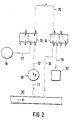
- a device which is shown schematically in FIG. 2, is advantageously used for taking a sample from a process line 20 (or a process vessel).
- This device comprises a suction line 11 which is connected to the process line 20 or to a process vessel and is connected to the inlet side of a pump 10.
- the pump 10 On the pressure side, the pump 10 is connected via a pressure line 12 to an inlet a of a first solenoid valve 13, the outlet b of which is connected to one end of a sample hose 15.
- the sample tube 15 is connected at its other end to an inlet b of a second solenoid valve 14, which in turn communicates with its one outlet a via a discharge line 16 to the process line 20 (or a process vessel).
- liquid removed from the process line 20 can thus be pumped through the sample tube 15, so that the content of the sample tube 15 matches the current content of the process line 20.
- a second inlet c of the first valve 13 is connected to a compressed gas source 18 via a compressed gas line 17.
- a second output c of the second valve 14 is connected to the Extraction line 19 connected (as described above) opens into the filling section 32.
- the solenoid valves 13 and 14 are now switched over (into the outer positions in FIG. 2), the content of the sample tube 15 and the remaining contents of the valves 13 and 14 are pressed by the compressed gas from the compressed gas source 18 through the extraction line 19 into the filling section 32 , the gas preferably being allowed to flow until residual droplets have also been conveyed into the filling section 32.
- This type of sampling enables an extraordinarily exact, reproducible dosage to be achieved in the simplest way, while at the same time the composition of the sample is not changed.
- the sampling device is also insensitive to liquids that are otherwise difficult to process with potentially abrasive solids, since all parts are “flushed” with process liquid on the one hand, and in abundance with compressed air on the other. This is particularly important in wastewater monitoring and complements the particularly effective cleaning of the device part shown in FIG. 1.
- the initial potential which arises can be used while the liquid remains essentially the same.
- a constant standard liquid is filled into the filling section 32 instead of a sample, so that the initial potential provides an exact measured value for assessing the surface condition of the electrodes 34 and 35.
- the controller 22 controls a warning device so that the electrodes can be serviced.
Landscapes
- Chemical & Material Sciences (AREA)
- Health & Medical Sciences (AREA)
- Life Sciences & Earth Sciences (AREA)
- Immunology (AREA)
- Pathology (AREA)
- Physics & Mathematics (AREA)
- Analytical Chemistry (AREA)
- Biochemistry (AREA)
- General Health & Medical Sciences (AREA)
- General Physics & Mathematics (AREA)
- Engineering & Computer Science (AREA)
- Chemical Kinetics & Catalysis (AREA)
- Electrochemistry (AREA)
- Food Science & Technology (AREA)
- Medicinal Chemistry (AREA)
- Sampling And Sample Adjustment (AREA)
- Automatic Analysis And Handling Materials Therefor (AREA)
- Polyesters Or Polycarbonates (AREA)
- Saccharide Compounds (AREA)
- Investigating Or Analysing Materials By Optical Means (AREA)
- Eye Examination Apparatus (AREA)
- Investigating Or Analysing Biological Materials (AREA)
- Investigating Or Analyzing Materials By The Use Of Electric Means (AREA)
Applications Claiming Priority (3)
| Application Number | Priority Date | Filing Date | Title |
|---|---|---|---|
| DE4008916 | 1990-03-20 | ||
| DE4008916A DE4008916C1 (enExample) | 1990-03-20 | 1990-03-20 | |
| PCT/EP1991/000441 WO1991014940A2 (de) | 1990-03-20 | 1991-03-08 | Vorrichtung zur automatisierten polyelektrolytbestimmung |
Publications (2)
| Publication Number | Publication Date |
|---|---|
| EP0521043A1 EP0521043A1 (de) | 1993-01-07 |
| EP0521043B1 true EP0521043B1 (de) | 1994-08-31 |
Family
ID=6402639
Family Applications (1)
| Application Number | Title | Priority Date | Filing Date |
|---|---|---|---|
| EP91906258A Expired - Lifetime EP0521043B1 (de) | 1990-03-20 | 1991-03-08 | Vorrichtung zur automatisierten polyelektrolytbestimmung |
Country Status (8)
| Country | Link |
|---|---|
| US (1) | US5408185A (enExample) |
| EP (1) | EP0521043B1 (enExample) |
| JP (1) | JPH05508008A (enExample) |
| AT (1) | ATE110850T1 (enExample) |
| CA (1) | CA2078543C (enExample) |
| DE (2) | DE4008916C1 (enExample) |
| NO (1) | NO911066L (enExample) |
| WO (1) | WO1991014940A2 (enExample) |
Cited By (2)
| Publication number | Priority date | Publication date | Assignee | Title |
|---|---|---|---|---|
| EP2034300A1 (de) | 2007-09-10 | 2009-03-11 | BTG Instruments GmbH | Vorrichtung zur Messung eines Strömungspotentials |
| DE102007043094A1 (de) | 2007-09-10 | 2009-04-02 | Btg Instruments Gmbh | Vorrichtung zur Messung eines Strömungspotentials |
Families Citing this family (16)
| Publication number | Priority date | Publication date | Assignee | Title |
|---|---|---|---|---|
| DE4243950C1 (de) * | 1992-12-23 | 1994-08-04 | Muetek Laser Und Optoelektroni | Vorrichtung zur Polyelektrolytbestimmung |
| ATE261117T1 (de) * | 1994-05-03 | 2004-03-15 | Muetek Analytic Gmbh | Vorrichtung zur polyelektrolytbestimmung |
| WO1997036173A1 (de) * | 1996-03-22 | 1997-10-02 | Dr. W. Kolb Ag | Vorrichtung zur ladungsbestimmung |
| DE19635318C2 (de) * | 1996-08-30 | 1999-05-20 | Muetek Analytic Gmbh | Verfahren und Vorrichtung zur Dickstoffmessung |
| DE19731184C2 (de) * | 1997-07-10 | 1999-10-07 | Atotech Deutschland Gmbh | Vorrichtung zur analytischen Überwachung eines Bades zur galvanotechnischen Behandlung von Substratoberflächen |
| US6107803A (en) * | 1997-10-31 | 2000-08-22 | Wang; Junli | Streaming current sensor |
| US5936151A (en) * | 1997-12-22 | 1999-08-10 | International Paper Company | Method and apparatus for measuring an electrical property of papermaking furnish |
| US6176974B1 (en) * | 1997-12-22 | 2001-01-23 | International Paper Company | Method for determining electrokinetic properties of papermaking furnish |
| AT503235B1 (de) * | 2002-08-09 | 2008-02-15 | Volker Dr Ribitsch | Verfahren und vorrichtung zur bestimmung des strömungspotentials bzw. zeta-potentials |
| DE102005001850B4 (de) * | 2005-01-10 | 2007-11-15 | Ese Embedded System Engineering Gmbh | Messeinrichtung und Verfahren zum Messen einer Größe einer Flüssigkeit |
| WO2007059910A1 (de) * | 2005-11-28 | 2007-05-31 | Btg Instruments Gmbh | Vorrichtung zur analyse von probeflüssigkeiten mit suspendierten stoffen |
| DE102011117681B4 (de) * | 2011-11-04 | 2013-08-14 | Particle Metrix Gmbh | Verfahren und Vorrichtung zur Messung des Grenzschichtpotentials von Partikeln und Makromolekülen in flüssigen polaren Medien |
| DE102014001759B4 (de) * | 2014-02-10 | 2016-01-07 | Particle Metrix Gmbh | Verfahren und Vorrichtung zur schnellen Analyse der Ladungscharakteristik und der Größenverteilung von Partikeln |
| JP7407369B2 (ja) * | 2020-06-26 | 2024-01-04 | パナソニックIpマネジメント株式会社 | 電解水生成装置および電解水生成装置の洗浄方法 |
| CN114923739B (zh) * | 2022-05-20 | 2022-12-09 | 山东省威海基础工程公司 | 一种金矿地质勘查用智能多重采样装置 |
| CN116359462B (zh) * | 2023-04-06 | 2024-10-18 | 皖江新兴产业技术发展中心 | 一种土壤修复前后监测方法 |
Family Cites Families (9)
| Publication number | Priority date | Publication date | Assignee | Title |
|---|---|---|---|---|
| NL301241A (enExample) * | 1963-12-02 | |||
| US3368145A (en) * | 1966-03-04 | 1968-02-06 | Dow Chemical Co | Apparatus for measuring charge condition within a solution |
| US3526827A (en) * | 1967-10-05 | 1970-09-01 | Dow Chemical Co | Apparatus for measuring charge condition within a solution |
| US4449101A (en) * | 1982-05-06 | 1984-05-15 | Process Development, Inc. | Jet wash for ultrasonic streaming current detector |
| US4446435A (en) * | 1982-05-06 | 1984-05-01 | Process Development, Inc. | Ultrasonic streaming current detector |
| US4769608A (en) * | 1987-02-20 | 1988-09-06 | Bryant Robert L | Self-cleaning streaming current monitor |
| US4825169A (en) * | 1987-07-09 | 1989-04-25 | Milton Roy Company | Ultrasonic streaming current detector |
| US4961147A (en) * | 1989-09-28 | 1990-10-02 | Moore Zack J | Apparatus for measuring the electric charge condition of non-conductive particles in a liquid medium |
| US5220283A (en) * | 1991-06-11 | 1993-06-15 | Milton Roy Company | Calibration of streaming current detection |
-
1990
- 1990-03-20 DE DE4008916A patent/DE4008916C1/de not_active Expired - Fee Related
-
1991
- 1991-03-08 CA CA002078543A patent/CA2078543C/en not_active Expired - Fee Related
- 1991-03-08 JP JP91505704A patent/JPH05508008A/ja active Pending
- 1991-03-08 EP EP91906258A patent/EP0521043B1/de not_active Expired - Lifetime
- 1991-03-08 AT AT91906258T patent/ATE110850T1/de not_active IP Right Cessation
- 1991-03-08 DE DE59102753T patent/DE59102753D1/de not_active Expired - Lifetime
- 1991-03-08 WO PCT/EP1991/000441 patent/WO1991014940A2/de not_active Ceased
- 1991-03-18 NO NO91911066A patent/NO911066L/no unknown
-
1992
- 1992-11-18 US US07/923,972 patent/US5408185A/en not_active Expired - Lifetime
Cited By (2)
| Publication number | Priority date | Publication date | Assignee | Title |
|---|---|---|---|---|
| EP2034300A1 (de) | 2007-09-10 | 2009-03-11 | BTG Instruments GmbH | Vorrichtung zur Messung eines Strömungspotentials |
| DE102007043094A1 (de) | 2007-09-10 | 2009-04-02 | Btg Instruments Gmbh | Vorrichtung zur Messung eines Strömungspotentials |
Also Published As
| Publication number | Publication date |
|---|---|
| ATE110850T1 (de) | 1994-09-15 |
| US5408185A (en) | 1995-04-18 |
| DE59102753D1 (de) | 1994-10-06 |
| WO1991014940A2 (de) | 1991-10-03 |
| EP0521043A1 (de) | 1993-01-07 |
| NO911066D0 (no) | 1991-03-18 |
| WO1991014940A3 (de) | 1991-11-28 |
| CA2078543A1 (en) | 1991-09-21 |
| CA2078543C (en) | 2001-07-24 |
| DE4008916C1 (enExample) | 1991-05-23 |
| JPH05508008A (ja) | 1993-11-11 |
| NO911066L (no) | 1991-09-23 |
Similar Documents
| Publication | Publication Date | Title |
|---|---|---|
| EP0521043B1 (de) | Vorrichtung zur automatisierten polyelektrolytbestimmung | |
| DE69514098T2 (de) | Einkolben-mehrzweckpumpe | |
| DE1598514A1 (de) | Verfahren zur Durchfuehrung von Blutuntersuchungen | |
| EP0185958B1 (de) | Verfahren und Vorrichtung zum Abmessen eines abfüllbaren Produktes | |
| EP3296075B1 (de) | Fördervorrichtung zum fördern eines viskosen materials aus einem behälter und verfahren zum betreiben der fördervorrichtung | |
| DE1214905B (de) | Elektrisches Zaehlgeraet fuer in einer Fluessigkeit suspendierte Teilchen | |
| DE2053119C3 (de) | Fluid verteiler | |
| EP3115609A1 (de) | Selbstreinigende pumpe | |
| DE3512222C2 (de) | Strömungsmechanische Pumpeinrichtung | |
| DE69223875T2 (de) | Verfahren zum Rühren und zur Probenentnahme einer flüssigen Probe | |
| DE68905698T2 (de) | Fliessinjektionsanalyse. | |
| DE60301579T2 (de) | Verfahren und Vorrichtung für Konzentrationsmessungen | |
| DE2233913B2 (de) | Dosiervorrichtung | |
| DE2513824C3 (de) | Vorrichtung zur aufeinanderfolgenden Entnahme kleiner Probenvolumina aus einem Flüssigkeitsstrom | |
| EP0681180B1 (de) | Vorrichtung zur Polyelektrolytbestimmung | |
| DE4122680C2 (de) | Rührwerksmühle | |
| DE2931017A1 (de) | Druckverstaerkersystem, insbesondere zur fluessigkeitsfoerderung in fluessigkeitschromatographen | |
| EP0710328B1 (de) | Verfahren und vorrichtung zum kontinuierlichen fördern scherempfindlicher fluide | |
| EP0668247B1 (de) | Einrichtung zum Behandeln von wässrigem Schlamm | |
| WO1991014508A1 (de) | Druckbehälter zum verspritzen einer flüssigkeit | |
| DE1553022A1 (de) | Vorrichtung zum Saugen von Fluessigkeit,Luft und festen Teilchen | |
| EP0093691B1 (de) | Kolbenpumpe für Flüssigkeiten | |
| DE3536624A1 (de) | Verfahren und vorrichtung zur steuerung des feststoff- oder dickstoffaustrages aus einem separator | |
| DE19832862C2 (de) | Dosierverfahren für Flüssigkeiten | |
| DE4142057C2 (enExample) |
Legal Events
| Date | Code | Title | Description |
|---|---|---|---|
| PUAI | Public reference made under article 153(3) epc to a published international application that has entered the european phase |
Free format text: ORIGINAL CODE: 0009012 |
|
| 17P | Request for examination filed |
Effective date: 19920902 |
|
| AK | Designated contracting states |
Kind code of ref document: A1 Designated state(s): AT BE CH DE DK ES FR GB IT LI NL SE |
|
| 17Q | First examination report despatched |
Effective date: 19930224 |
|
| GRAA | (expected) grant |
Free format text: ORIGINAL CODE: 0009210 |
|
| RAP1 | Party data changed (applicant data changed or rights of an application transferred) |
Owner name: MUETEK ANALYTIC GMBH |
|
| AK | Designated contracting states |
Kind code of ref document: B1 Designated state(s): AT BE CH DE DK ES FR GB IT LI NL SE |
|
| PG25 | Lapsed in a contracting state [announced via postgrant information from national office to epo] |
Ref country code: DK Effective date: 19940831 Ref country code: BE Effective date: 19940831 Ref country code: NL Effective date: 19940831 Ref country code: ES Free format text: THE PATENT HAS BEEN ANNULLED BY A DECISION OF A NATIONAL AUTHORITY Effective date: 19940831 |
|
| REF | Corresponds to: |
Ref document number: 110850 Country of ref document: AT Date of ref document: 19940915 Kind code of ref document: T |
|
| ET | Fr: translation filed | ||
| GBT | Gb: translation of ep patent filed (gb section 77(6)(a)/1977) |
Effective date: 19940822 |
|
| REF | Corresponds to: |
Ref document number: 59102753 Country of ref document: DE Date of ref document: 19941006 |
|
| ITF | It: translation for a ep patent filed | ||
| EAL | Se: european patent in force in sweden |
Ref document number: 91906258.8 |
|
| NLV1 | Nl: lapsed or annulled due to failure to fulfill the requirements of art. 29p and 29m of the patents act | ||
| PG25 | Lapsed in a contracting state [announced via postgrant information from national office to epo] |
Ref country code: CH Effective date: 19950331 Ref country code: LI Effective date: 19950331 |
|
| PLBE | No opposition filed within time limit |
Free format text: ORIGINAL CODE: 0009261 |
|
| STAA | Information on the status of an ep patent application or granted ep patent |
Free format text: STATUS: NO OPPOSITION FILED WITHIN TIME LIMIT |
|
| 26N | No opposition filed | ||
| REG | Reference to a national code |
Ref country code: CH Ref legal event code: PL |
|
| PGFP | Annual fee paid to national office [announced via postgrant information from national office to epo] |
Ref country code: FR Payment date: 19960318 Year of fee payment: 6 |
|
| PGFP | Annual fee paid to national office [announced via postgrant information from national office to epo] |
Ref country code: AT Payment date: 19960325 Year of fee payment: 6 |
|
| PG25 | Lapsed in a contracting state [announced via postgrant information from national office to epo] |
Ref country code: AT Effective date: 19970308 |
|
| PG25 | Lapsed in a contracting state [announced via postgrant information from national office to epo] |
Ref country code: FR Free format text: LAPSE BECAUSE OF NON-PAYMENT OF DUE FEES Effective date: 19971128 |
|
| REG | Reference to a national code |
Ref country code: FR Ref legal event code: ST |
|
| REG | Reference to a national code |
Ref country code: GB Ref legal event code: IF02 |
|
| PGFP | Annual fee paid to national office [announced via postgrant information from national office to epo] |
Ref country code: SE Payment date: 20020325 Year of fee payment: 12 |
|
| PG25 | Lapsed in a contracting state [announced via postgrant information from national office to epo] |
Ref country code: SE Free format text: LAPSE BECAUSE OF NON-PAYMENT OF DUE FEES Effective date: 20030309 |
|
| EUG | Se: european patent has lapsed | ||
| PG25 | Lapsed in a contracting state [announced via postgrant information from national office to epo] |
Ref country code: IT Free format text: LAPSE BECAUSE OF NON-PAYMENT OF DUE FEES Effective date: 20050308 |
|
| PGFP | Annual fee paid to national office [announced via postgrant information from national office to epo] |
Ref country code: GB Payment date: 20070430 Year of fee payment: 17 |
|
| GBPC | Gb: european patent ceased through non-payment of renewal fee |
Effective date: 20080308 |
|
| PG25 | Lapsed in a contracting state [announced via postgrant information from national office to epo] |
Ref country code: GB Free format text: LAPSE BECAUSE OF NON-PAYMENT OF DUE FEES Effective date: 20080308 |
|
| PGFP | Annual fee paid to national office [announced via postgrant information from national office to epo] |
Ref country code: DE Payment date: 20100329 Year of fee payment: 20 |
|
| REG | Reference to a national code |
Ref country code: DE Ref legal event code: R071 Ref document number: 59102753 Country of ref document: DE |
|
| PG25 | Lapsed in a contracting state [announced via postgrant information from national office to epo] |
Ref country code: DE Free format text: LAPSE BECAUSE OF EXPIRATION OF PROTECTION Effective date: 20110308 |