EP0521037B1 - Exercising apparatus - Google Patents
Exercising apparatus Download PDFInfo
- Publication number
- EP0521037B1 EP0521037B1 EP91906133A EP91906133A EP0521037B1 EP 0521037 B1 EP0521037 B1 EP 0521037B1 EP 91906133 A EP91906133 A EP 91906133A EP 91906133 A EP91906133 A EP 91906133A EP 0521037 B1 EP0521037 B1 EP 0521037B1
- Authority
- EP
- European Patent Office
- Prior art keywords
- piston
- plunger rod
- main
- cylinder
- main cylinder
- Prior art date
- Legal status (The legal status is an assumption and is not a legal conclusion. Google has not performed a legal analysis and makes no representation as to the accuracy of the status listed.)
- Expired - Lifetime
Links
- 238000006073 displacement reaction Methods 0.000 claims abstract description 45
- 239000007788 liquid Substances 0.000 claims abstract description 19
- 238000004891 communication Methods 0.000 claims abstract description 5
- 238000007789 sealing Methods 0.000 claims description 35
- 230000008878 coupling Effects 0.000 claims description 9
- 238000010168 coupling process Methods 0.000 claims description 9
- 238000005859 coupling reaction Methods 0.000 claims description 9
- 125000006850 spacer group Chemical group 0.000 claims description 4
- 230000002093 peripheral effect Effects 0.000 claims description 3
- 239000003921 oil Substances 0.000 description 23
- 238000010276 construction Methods 0.000 description 4
- 230000009471 action Effects 0.000 description 3
- 230000008901 benefit Effects 0.000 description 3
- 238000013461 design Methods 0.000 description 3
- 230000000694 effects Effects 0.000 description 3
- 238000012546 transfer Methods 0.000 description 3
- 210000004907 gland Anatomy 0.000 description 2
- 239000010720 hydraulic oil Substances 0.000 description 2
- 230000007246 mechanism Effects 0.000 description 2
- 238000000034 method Methods 0.000 description 2
- 210000003205 muscle Anatomy 0.000 description 2
- 230000008859 change Effects 0.000 description 1
- 230000007812 deficiency Effects 0.000 description 1
- 230000036541 health Effects 0.000 description 1
- 210000003141 lower extremity Anatomy 0.000 description 1
- 238000012986 modification Methods 0.000 description 1
- 230000004048 modification Effects 0.000 description 1
- 230000002035 prolonged effect Effects 0.000 description 1
Images


Classifications
-
- A—HUMAN NECESSITIES
- A63—SPORTS; GAMES; AMUSEMENTS
- A63B—APPARATUS FOR PHYSICAL TRAINING, GYMNASTICS, SWIMMING, CLIMBING, OR FENCING; BALL GAMES; TRAINING EQUIPMENT
- A63B21/00—Exercising apparatus for developing or strengthening the muscles or joints of the body by working against a counterforce, with or without measuring devices
- A63B21/00058—Mechanical means for varying the resistance
- A63B21/00069—Setting or adjusting the resistance level; Compensating for a preload prior to use, e.g. changing length of resistance or adjusting a valve
- A63B21/00072—Setting or adjusting the resistance level; Compensating for a preload prior to use, e.g. changing length of resistance or adjusting a valve by changing the length of a lever
-
- A—HUMAN NECESSITIES
- A63—SPORTS; GAMES; AMUSEMENTS
- A63B—APPARATUS FOR PHYSICAL TRAINING, GYMNASTICS, SWIMMING, CLIMBING, OR FENCING; BALL GAMES; TRAINING EQUIPMENT
- A63B21/00—Exercising apparatus for developing or strengthening the muscles or joints of the body by working against a counterforce, with or without measuring devices
- A63B21/008—Exercising apparatus for developing or strengthening the muscles or joints of the body by working against a counterforce, with or without measuring devices using hydraulic or pneumatic force-resisters
- A63B21/0083—Exercising apparatus for developing or strengthening the muscles or joints of the body by working against a counterforce, with or without measuring devices using hydraulic or pneumatic force-resisters of the piston-cylinder type
-
- A—HUMAN NECESSITIES
- A63—SPORTS; GAMES; AMUSEMENTS
- A63B—APPARATUS FOR PHYSICAL TRAINING, GYMNASTICS, SWIMMING, CLIMBING, OR FENCING; BALL GAMES; TRAINING EQUIPMENT
- A63B21/00—Exercising apparatus for developing or strengthening the muscles or joints of the body by working against a counterforce, with or without measuring devices
- A63B21/40—Interfaces with the user related to strength training; Details thereof
- A63B21/4041—Interfaces with the user related to strength training; Details thereof characterised by the movements of the interface
- A63B21/4045—Reciprocating movement along, in or on a guide
Definitions
- the invention relates to an exercising apparatus according to the preamble of claim 1, which is an exercising apparatus of the type adapted to be used by humans to exercise muscles and other body parts.
- exercising apparatus Many different types can be purchased by persons anxious to improve their health and physical abilities.
- the simplest would be spring-extension stretching devices to be used manually, but other types, too numerous to enumerate, either occupy an unduly large space in storage or use, or they lack portability.
- a further disadvantage is that most have strong spring-recoil mechanisms which can lead to body strain or to accidents of one kind or another. Lack of fine adjustability to suit different users or various operating conditions and requirements can also be a disadvantage with most current types of exercising apparatus.
- the present invention has been devised with the aforementioned current deficiencies and disadvantages in mind, and it has for its principal object the provision of improved exercising apparatus having novel features whereby it will be safer and more effective than known types in relation to portability and adjustability in particular.
- the invention also aims to provide such novel forms of exercising apparatus which will use non-recoil principles and which can be adapted to use in different applications so that any desired muscle can be exercised, while infinitely variable resistance can be utilised as required.
- Other objects and advantages of the invention will be hereinafter apparent.
- the invention resides broadly in an exercising apparatus according to the preamble of claim 1 which is characterized in that said main cylinder and said displacement cylinder being mounted about spaced parallel longitudinal axes with their external peripheries in contact or in closely adjacent relationship and so that the closure piston at all stages of its operative movement is disposed beside the main cylinder and externally thereof between the two ends of the main cylinder.
- the displacement cylinder is preferably and suitably of smaller diameter.
- the adjustable aperture means is provided in and extending through said main piston between the two opposite sides of said main cylinder, there being provided adjustment-control means for said adjustable aperture means leading operatively from said main piston to said handle means.
- said main piston includes a fixed piston member secured rigidly to said plunger rod, and an adjustable piston member adjustably rotatable about the axis of said main piston and said plunger rod relative to said fixed piston member, there being apertures through both said piston members adapted to be brought into selected degrees of register to vary the permitted flow according to the rotational disposition of said adjustable piston member, said adjustment-control means comprising a control rod passing rotatably through a bore of said plunger rod and extending from said adjustable piston member to said handle means, rotation-control means being provided at the handle means end of said control rod whereby the latter may be rotated to a desired extent to adjust the setting of said adjustable piston member relative to said fixed piston member.
- the fixed piston member and adjustable piston member are suitably of disc-like form with flat co-acting faces in normally-sealing rotatable contact
- the apertures may include part-circumferential peripheral slots in each disc-like piston member for registering to desired extent upon adjustment of said adjustable piston member.
- the apertures may include a series of cylindrical apertures arranged on an arc about the plunger rod axis through each piston member and inwardly of the periphery thereof, the apertures of the two piston members being arranged to register to desired extent upon adjustment of said adjustable piston member.
- the displacement cylinder has its said one end communicating with said main cylinder at the side of the latter having said sealing means through which said plunger rod passes, the parts being so made and arranged that liquid under pressure at said end of the displacement cylinder acts also to increase the sealing ability of said sealing means against leakage of liquid past said sealing means to the exterior of the main cylinder.
- the sealing means may include two spaced U-shaped sealing rings or buckets through which the plunger rod passes, the space between said rings having an entry port from the adjacent end of the displacement cylinder, a radially-apertured spacer sleeve being provided to surround the plunger rod and maintain spacing of the sealing rings.
- the closure piston may be operatively connected to said plunger rod by coupling means whereby movement of the plunger rod causes a corresponding predetermined movement of the closure piston while maintaining said liquid-filled condition of said main cylinder, the diameter of the closure piston and displacement cylinder being less than the diameter of the main cylinder and main piston so that said predetermined movement of the closure piston is over a lesser length than the movement of the plunger rod.
- the coupling means may include a single cable and pulley arranged so that withdrawal of the plunger rod causes movement of the closure piston in the direction towards that end of the displacement cylinder communicating with said main cylinder.
- the coupling means may include a single cable and plurality of pulleys arranged so that withdrawal of the plunger rod positively and instantly draws the closure piston in the direction towards that end of the displacement cylinder communicating with said main cylinder, while the return movement of the plunger rod positively and instantly draws the closure piston in the direction away from that end of the displacement cylinder communicating with said main cylinder.
- the coupling means may include rack and pinion means instead of the cable and pulleys.
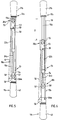
- FIG. 1 and 2 The various embodiments of the invention will illustrate that there is provided an adjustable damper-type exercising device designed for use in the conventional application of two-handed expander as apparent from Figs. 1 and 2 in particular, or for attachment to frames for exercising locations and/or to fixed brackets, or as the hydraulic part of elaborate exercising machines or the like.
- the simplest form of the invention will be clear from the embodiment illustrated second and shown in Figs. 7 and 8 where the elongate frame is indicated generally by the numeral 10 and houses a longitudinal hydraulic main cylinder 13 which in this construction forms part of the frame 10.
- the frame 10 in this instance has a fixed mounting end 11 and a movable or handle end section or assembly 12.
- the longitudinal main cylinder 13 defines a main chamber 14 to be filled with hydraulic oil as the necessary non-compressible liquid which is constrained to move only within the chamber 14.
- the end of the main cylinder 13 opposite the mounting end 11 has sealing means through which a hollow tubular plunger rod 15 is sealably slidable axially of the cylinder 13, being connected at its inner end to a main piston 18 which is able to be moved by the plunger rod 15 in sealably slidable manner to define two opposite sides of the main cylinder 13 at opposite ends of the main chamber 14.
- the main piston 18 comprises two piston members 16 and 17 which in this case are of disc-like form having machined faces in tight but relatively rotational contact.
- the lower end of the plunger rod 15 (when considered in the disposition illustrated) is secured to the uppermost piston member 16 which constitutes a fixed piston member, while the other piston member 17 is secured to the lower extremity of an innermost control rod 19 extending through an axial bore of the fixed piston member 16 and axially upwards through the plunger rod 15.
- the piston members 16 and 17 have identical part-circumferential peripheral slots 71 which can be out of register as shown in Fig. 9A to prevent through-flow completely, or by rotating the adjustable lower piston member 17 as shown by the arrow 72' of Fig. 9B, the apertures 71 may be brought into register to desired extent to allow flow of liquid through the main piston 18 at desired rate.
- the free end of the plunger rod 15 (which is the upper end as illustrated) extends through any suitable sealing means comprising both air and oil seal members, as illustrated, within an upper sealing cap 20, and it has handle assembly members secured to its upper end as illustrated at 21. It will be seen from Fig. 8 that the handle end may be moved to withdraw the plunger rod 15 or subsequently retract it, various pressures being experienced as resistance to movement of the piston during such movements, with different resistances according to the degree of register of the apertures 71 through the faces of the piston members 16 and 17 of the main piston 18 as the latter is moved at the inner end of the plunger rod 15.
- the end of the main cylinder 13 opposite the sealing cap 20 connects via a connector vessel 73' with the lower open end of a displacement cylinder 22 mounted in spaced parallel relationship to the main cylinder 13 but of lesser diameter as illustrated.
- a displacement cylinder 22 mounted in spaced parallel relationship to the main cylinder 13 but of lesser diameter as illustrated.
- oil will be displaced up the displacement cylinder 22 against a movable closure piston 23 mounted in sealably slidable manner, the piston 23 being biassed in this instance by spring loading in the form of a spring 24 held by retainer cap 74 arranged to urge the closure piston normally in the direction towards the connector vessel 73'.
- the vacuum normally created is offset by oil moving back to the lower end of the main cylinder 13 under the pressure of the spring 24, ensuring that there is maintained a liquid-filled condition of the main cylinder 13 at all times regardless of the positions occupied by the main piston 18 and the plunger rod 15.
- Adjustment of the adjustable piston member 17 of the main piston 18 can be made from outside the apparatus and main chamber 14 by means of a dial 25 at the handle 21 permitting rotation of the control rod 19 which causes rotation of the adjustable member 17 relative to the fixed piston member 16.
- This adjustment at the dial 25 allows a desired flow of oil to pass through the main piston 18, resulting in pressure against movement of the plunger rod 15 in and out, with the amount of resisting pressure depending upon the size of the adjustable aperture means 71 through which the oil is forced. It will be noted that the resistance will remain constant through the full stroke in or out, and it works against the viscosity of the oil, and not through pressure of oil.
- the invention provides a system which is sealed with respect to the outer atmosphere, the inner spaces being filled with a non-compressible liquid which is displaced in either direction by the main piston through apertures in the main piston from one side of the main cylinder to the other on opposite sides of the main piston, while the force to be overcome in moving the main piston arises from controlled throttling of the non-compressible liquid when the latter is set into motion by the piston for passage through the apertures in the piston.
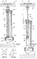
- the frame 10 a is elongated to extend between a fixed mounting end 11 a and a movable end 12 a , there being a main cylinder 13 a defining a main chamber 14 a to be filled with hydraulic oil.
- Axially within the main cylinder 13 a is a hollow plunger rod 15 a connected at its lower end (in the disposition illustrated) to the upper fixed piston plate or member 16 a of the main piston 18 a , there being also a lower adjustable piston plate or member 17 a secured to an innermost control rod 19 a extending up through the plunger rod 15 a .
- the members 16 a and 17 a have machined faces in tight contact but relative rotation is obtained by turning the control rod 19 a which causes apertures to register to desired extent to give infinitely variable flow from one side of the piston 18 a to the other.
- dotted lines indicate passages 26 when flow is allowed by the relative disposition of the members 16 a and 17 a .
- the adjustable piston member 17 a has a series of cylindrical apertures 72 arranged on an arc traced out about its axis but inwardly of its periphery. These increase progressively in diameter and may communicate according to the degree of rotation with larger equally-spaced openings 73 partway through the upper fixed member 16 a and leading from an extended arcuate slot 74 for ease of flow.
- alternative design details may be easily devised for the nature of the apertures of the two piston members and the methods whereby these are secured in relative rotatable manner to the plunger rod on the one hand and to the control rod on the other hand.
- the upper end of the plunger rod 15 a extends through air and oil seal members held within an upper cap assembly 20 a and it has handle assembly members secured to its upper end as indicated at 21 a .
- a varied pressure resistance is felt at the handle end 21 a as the plunger rod 15 a is moved thereby in and out of the chamber 14 a , the different resistances being caused by changing the degree of rotation of the apertures, such as the apertures 72, through the piston members 16 a and 17 a of the piston 18 a which is movable with the end of the plunger rod 15 a .
- a freely rotatable pulley 29 at the free outer end of the guide rod 24 a Passing round the pulley 29 is a flexible wire or inextensible cable 30 which has one end affixed at 31 to the displacement cylinder 22 a while its other end is affixed at 32 relative to the plunger rod 15 a through its outer handle end 12 a .
- the long stroke of the plunger rod 15 a is accompanied by a small proportional movement of the guide rod 24 a - suitably one-half or similar predetermined relationship according to the relative diameters of the cylinders.
- the dimensions are chosen so that the closure piston 23 a is in position to ensure that the oil volume is properly contained at the correct pressure while the flexible wire or cable 30 is both effective and taut at all times, with withdrawal of the plunger rod 15 a causing movement of the closure piston 23 a towards that end of the displacement cylinder which communicates with the main cylinder.
- the upper cap assembly 20 a for the main cylinder 13 a may incorporate a sealing gland comprising upper and lower opposed flexible U-shaped rings, buckets or cups 34 and 35 held apart by a spacer sleeve 36, restrained by flanges of the sealing rings 34 and 35 as illustrated, to be concentric about the plunger rod 15 a .
- the dimensions be predetermined and designed for maximum efficiency, it being necessary that the withdrawn displacement section of the plunger rod 15 a has a total volume equal to the displacement volume in the displacement cylinder 22 a through resultant movement of the guide rod 24 a for the closure piston 23 a .
- the adjustable piston member or plate or disc 17 a of the piston 18 a is rotated by the dial 25 a , and to ensure efficiency O-rings 41 and 42 can be provided around the piston members 16 a and 17 a , as illustrated, allowing for sealing on axial sliding and turning of the movable piston member, but without the piston 18 a binding against the wall of the chamber 14 a .
- the upper one 34 is effective as an oil-leak seal, while the lower one is principally an air-stop seal.
- a further O-ring (not shown) is provided about the control rod 19 a to ensure sealing at its end adjacent the dial 25 a .
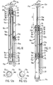
- Figs. 1 to 6 The same general principles, together with further features, are illustrated in the refined embodiment of the invention shown in Figs. 1 to 6, in which similar parts are given the same numerals as before followed by the letter "b".
- This is set up as a two-handed manual form in which the frame 10 b has at its end 12 b a handle 21 b fitted with a dial 25 b , the other end 11 b also being provided with a similar handle 43.
- the two handles 21 b and 43 are secured to respective mechanism housings 44 and 45 which are slidable telescopically as the plunger rod 15 b is moved in and out.
- main cylinder 13 b plunger rod 15 b , displacement cylinder 22 b , closure piston 23 b and guide rod 24 b are the same as in Figs. 10 and 11, except that the pulley and cable arrangements have been changed so that withdrawal of the plunger rod 15 b positively and instantly draws the closure piston 23 b in the same direction which is towards that end of the displacement cylinder 22 b communicating with the main cylinder 13 b , while return movement of the plunger rod 15 b positively and instantly draws the closure piston 23 b in the opposite direction.
- the sealing cap 20 b is modified to provide a guide for a plunger-follower rod 50 parallel to the plunger rod 15 b and secured at one end to the same mounting adjacent the handle 21 b for sliding movement with the plunger rod 15 b .
- the free end of rod 50 is secured at 51 to a cable 52 having an upward run 53 and a downward run 54.
- the upward run 53 extends along the plunger-follower rod 50 to the sealing cap 20 b where it passes over an uppermost pulley 55 on said cap 20 b and then right down to a lowermost pulley 56 mounted rotatably adjacent the bottom handle 11 b , thereafter passing up and over a pulley 58 on the free end of the guide rod 24 b before finally passing down and being secured at 58 to the bottom handle 11 b .
- the said downward run 54 of the cable 52 extends down to and around another pulley 58 on the free end of the guide rod 24 b (about the same axis as that of the pulley 57) and then upwards to have its end secured at 59 to the top cap 20 b .
- the cable sections themselves are omitted from Figs. 3 and 4 for the sake of clarity but are shown diagrammatically in Figs. 5 and 6, where the cable 52 has its upward run 53 shown in full outline and its downward run 54 shown in dotted outline.
- the connection at 51 is the equivalent of a clamping arrangement for a continuous run so that the effective cable length remains continuous and taut at all times.
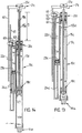
- this type of cable arrangement is to overcome possible disadvantages of the other embodiments of Figs. 7 and 8 and Figs. 10 and 11 so far as possible air-entry to the cylinders 13 b and 22 b might occur as a result of prolonged use. If air should enter, oil would be displaced resulting in less movement; the oil would became aerated resulting in movement which could be unsmooth, erratic or jerky, or even noisy; while additionally any air present would be subject to temperature change which might result in expanding air pushing some oil out, whereafter more air could be sucked in when the conditions cool. In such a case, the oil seals which are designed to keep the oil in would allow air to be sucked in past the oil seals when the air shrinks again.
- the plunger-follower rod 50 is replaced by a follower rack 60 parallel to the plunger rod 15 c and movable therewith in spaced parallel relationship.
- the guide rod 24 c for the closure piston 23 c has its free end coupled to a follower rack 61, the two follower racks 60 and 61 meshing with two pinions 62 and 63 secured rigidly on a common axis of rotation on the frame adjacent the cap 20 c to rotate freely but in unison.
Landscapes
- Health & Medical Sciences (AREA)
- Life Sciences & Earth Sciences (AREA)
- Biophysics (AREA)
- Orthopedic Medicine & Surgery (AREA)
- General Health & Medical Sciences (AREA)
- Physical Education & Sports Medicine (AREA)
- Actuator (AREA)
- Eye Examination Apparatus (AREA)
- Massaging Devices (AREA)
- Electrical Discharge Machining, Electrochemical Machining, And Combined Machining (AREA)
- Fluid-Damping Devices (AREA)
- Supply Devices, Intensifiers, Converters, And Telemotors (AREA)
Applications Claiming Priority (5)
| Application Number | Priority Date | Filing Date | Title |
|---|---|---|---|
| AU9242/90 | 1990-03-22 | ||
| AUPJ924290 | 1990-03-22 | ||
| AU868/90 | 1990-06-27 | ||
| AUPK086890 | 1990-06-27 | ||
| PCT/AU1991/000109 WO1991014482A1 (en) | 1990-03-22 | 1991-03-22 | Exercising apparatus |
Publications (3)
| Publication Number | Publication Date |
|---|---|
| EP0521037A1 EP0521037A1 (en) | 1993-01-07 |
| EP0521037A4 EP0521037A4 (OSRAM) | 1994-03-16 |
| EP0521037B1 true EP0521037B1 (en) | 1997-10-22 |
Family
ID=25643831
Family Applications (1)
| Application Number | Title | Priority Date | Filing Date |
|---|---|---|---|
| EP91906133A Expired - Lifetime EP0521037B1 (en) | 1990-03-22 | 1991-03-22 | Exercising apparatus |
Country Status (7)
| Country | Link |
|---|---|
| US (1) | US5250015A (OSRAM) |
| EP (1) | EP0521037B1 (OSRAM) |
| JP (1) | JP3073521B2 (OSRAM) |
| AT (1) | ATE159430T1 (OSRAM) |
| CA (1) | CA2078226C (OSRAM) |
| DE (1) | DE69128031T2 (OSRAM) |
| WO (1) | WO1991014482A1 (OSRAM) |
Cited By (1)
| Publication number | Priority date | Publication date | Assignee | Title |
|---|---|---|---|---|
| DE102016114110A1 (de) * | 2016-07-29 | 2018-02-01 | Betterguards Technology Gmbh | Vorrichtung zum adaptiven Dämpfen einer Körperbewegung |
Families Citing this family (16)
| Publication number | Priority date | Publication date | Assignee | Title |
|---|---|---|---|---|
| US5486150A (en) * | 1993-04-30 | 1996-01-23 | Randolph; Lucian | Exercise system, apparatus and method |
| US5906565A (en) * | 1996-04-26 | 1999-05-25 | Hydroforce, Inc. | Liquid resistance or therapy system for use with an exercise and/or therapy apparatus |
| US5735780A (en) * | 1996-05-08 | 1998-04-07 | Genevieve M. Griffin | Chest and body exerciser |
| US6106922A (en) * | 1997-10-03 | 2000-08-22 | 3M Innovative Company | Coextruded mechanical fastener constructions |
| US6482128B1 (en) | 1998-11-06 | 2002-11-19 | Acinonyx Company | Run specific training method |
| US6666801B1 (en) | 1999-11-05 | 2003-12-23 | Acinonyx Company | Sports specific training method and apparatus |
| CN1238076C (zh) * | 2003-05-07 | 2006-01-25 | 李荣德 | 女性阴道肌肉锻炼器 |
| DE10347542A1 (de) * | 2003-10-14 | 2005-05-19 | Mirko Mohr | Trainingsgerät |
| FR2883193A1 (fr) * | 2005-03-21 | 2006-09-22 | Farida Mekdoud | Appareil de musculation aquatique |
| US7762934B1 (en) * | 2005-05-02 | 2010-07-27 | Foi Group, Llc | Exercise apparatus based on a variable mode hydraulic cylinder and method for same |
| WO2007056245A1 (en) * | 2005-11-03 | 2007-05-18 | Gerstung Siegfried H H | Exercise glider device |
| US20100179035A1 (en) * | 2009-01-12 | 2010-07-15 | Eric Scott Carnahan | Multipurpose Exercise Machine Utilizing Vacuum Springs |
| CO6600214A1 (es) * | 2011-07-01 | 2013-01-18 | Serinpet Ltda Representaciones Y Servicios De Petroleos | Equipo de entrenamiento fisico que utiliza una palanca y un sistema hidraúlicos como elementos de resistencia mecánica |
| US9180332B1 (en) | 2013-10-31 | 2015-11-10 | Juan M. Tenorio | Compressive exercise device |
| DE102015004444A1 (de) * | 2015-04-04 | 2016-12-15 | Tim Borrmann | Übungsgerät für die Rotatorenmanschette der Schulter |
| US10456615B1 (en) | 2018-01-02 | 2019-10-29 | Raymond Anthony | Pneumatic exercise device |
Family Cites Families (17)
| Publication number | Priority date | Publication date | Assignee | Title |
|---|---|---|---|---|
| US1707449A (en) * | 1928-01-07 | 1929-04-02 | Jerome I Rodale | Physical-exercising device |
| US2825563A (en) * | 1955-05-16 | 1958-03-04 | Roger S Health Equipment Inc | Exercising machine |
| DE1195615B (de) * | 1958-12-19 | 1965-06-24 | Hemscheidt Maschf Hermann | Hydraulischer Stossdaempfer, insbesondere fuer Kraftfahrzeuge |
| US3834696A (en) * | 1973-05-16 | 1974-09-10 | Sam Rubin | Double-acting hydraulic exerciser |
| US4148479A (en) * | 1977-06-24 | 1979-04-10 | Donald Spector | Hydraulic force resister |
| US4183520A (en) * | 1978-03-09 | 1980-01-15 | Chase Daniel F | Exercising device having operably interconnected primary and secondary pivot arms |
| US4291787A (en) * | 1979-02-16 | 1981-09-29 | Brentham Jerry D | Exercising device with double acting hydraulic cylinder |
| US4290599A (en) * | 1979-10-29 | 1981-09-22 | Issac Berger | Exerciser |
| EP0030833A1 (en) * | 1979-12-06 | 1981-06-24 | D.H. CULVERWELL & SON LIMITED | Exercising apparatus |
| GB2124916A (en) * | 1982-08-11 | 1984-02-29 | Charles David Sinclair Gaskill | Exercise apparatus |
| CA1191516A (en) * | 1983-05-11 | 1985-08-06 | John B. Rogers | Abductor-adductor exercise device |
| EP0179818A4 (en) * | 1984-04-24 | 1987-09-21 | Comdox Pty Ltd | LINEAR MOTION RESISTANCE CELL. |
| US4651986A (en) * | 1984-11-22 | 1987-03-24 | Wang Shoei Muh | Hydraulic exerciser |
| FR2576651A1 (fr) * | 1985-01-28 | 1986-08-01 | Vanhoutte Daniele | Dispositif de verin hydraulique, notamment pour appareil de musculation |
| FR2605231B2 (fr) * | 1985-12-04 | 1989-04-14 | Miccoli Cosimo | Systeme hydraulique applique aux appareils de musculation |
| WO1987006666A1 (en) * | 1986-04-30 | 1987-11-05 | Comdox No. 70 Pty. Limited | Improved linear motion resistance cell |
| US4880230A (en) * | 1988-06-28 | 1989-11-14 | Gerry Cook | Pneumatic exercise device |
-
1991
- 1991-03-22 AT AT91906133T patent/ATE159430T1/de not_active IP Right Cessation
- 1991-03-22 DE DE69128031T patent/DE69128031T2/de not_active Expired - Fee Related
- 1991-03-22 JP JP03505619A patent/JP3073521B2/ja not_active Expired - Fee Related
- 1991-03-22 EP EP91906133A patent/EP0521037B1/en not_active Expired - Lifetime
- 1991-03-22 US US07/927,431 patent/US5250015A/en not_active Expired - Lifetime
- 1991-03-22 WO PCT/AU1991/000109 patent/WO1991014482A1/en not_active Ceased
- 1991-03-22 CA CA002078226A patent/CA2078226C/en not_active Expired - Fee Related
Cited By (1)
| Publication number | Priority date | Publication date | Assignee | Title |
|---|---|---|---|---|
| DE102016114110A1 (de) * | 2016-07-29 | 2018-02-01 | Betterguards Technology Gmbh | Vorrichtung zum adaptiven Dämpfen einer Körperbewegung |
Also Published As
| Publication number | Publication date |
|---|---|
| WO1991014482A1 (en) | 1991-10-03 |
| EP0521037A1 (en) | 1993-01-07 |
| DE69128031T2 (de) | 1998-04-16 |
| JPH05505539A (ja) | 1993-08-19 |
| ATE159430T1 (de) | 1997-11-15 |
| US5250015A (en) | 1993-10-05 |
| CA2078226C (en) | 2002-05-14 |
| EP0521037A4 (OSRAM) | 1994-03-16 |
| JP3073521B2 (ja) | 2000-08-07 |
| CA2078226A1 (en) | 1991-09-23 |
| DE69128031D1 (de) | 1997-11-27 |
Similar Documents
| Publication | Publication Date | Title |
|---|---|---|
| EP0521037B1 (en) | Exercising apparatus | |
| US5011142A (en) | Exercise control system | |
| US3369403A (en) | Hydraulic muscle strength developing apparatus | |
| US4326707A (en) | Hydraulic exerciser | |
| US4063726A (en) | Electronically controlled hydraulic exercising system | |
| US5622527A (en) | Independent action stepper | |
| US5376135A (en) | Adjustable hydraulic damper | |
| US3944221A (en) | Resistance device for a gymnastics apparatus | |
| BR0109085A (pt) | Sistema de amortecimento de vìdeo que usa um amortecedor hidráulico com um campo que responde a um controle de fluido | |
| US5527251A (en) | Compressible fluid-based, adjustable resistance hydraulic system for exercise equipment | |
| US3606318A (en) | Fluid resistant type exercising device | |
| EP0967408A3 (de) | Längenverstellbare Gasfeder | |
| WO1996011724A9 (en) | Compressible fluid-based, adjustable resistance hydraulic system for exercise equipment | |
| EP3436717A2 (de) | Trainingsgerät und verfahren | |
| WO1993007934A1 (en) | Hydraulic exercise apparatus | |
| NO160625B (no) | Overflatestyrt produksjonssikringsventil. | |
| WO2006013432A1 (en) | Reversible resistance assembly for hydraulic exercise apparatus | |
| US20070129223A1 (en) | Weight lifting simulator apparatus | |
| AU7469391A (en) | Exercising apparatus | |
| US4854577A (en) | Exercise means | |
| US20070232467A1 (en) | Reciprocable load resisting device | |
| US8007418B2 (en) | Portable resistance training device | |
| KR101286196B1 (ko) | 공압장치 및 이를 이용한 운동기구 | |
| US4601467A (en) | Valve module and apparatus therefor | |
| CN1037940C (zh) | 健身器 |
Legal Events
| Date | Code | Title | Description |
|---|---|---|---|
| PUAI | Public reference made under article 153(3) epc to a published international application that has entered the european phase |
Free format text: ORIGINAL CODE: 0009012 |
|
| 17P | Request for examination filed |
Effective date: 19920917 |
|
| AK | Designated contracting states |
Kind code of ref document: A1 Designated state(s): AT BE CH DE DK ES FR GB GR IT LI LU NL SE |
|
| A4 | Supplementary search report drawn up and despatched |
Effective date: 19940126 |
|
| AK | Designated contracting states |
Kind code of ref document: A4 Designated state(s): AT BE CH DE DK ES FR GB GR IT LI LU NL SE |
|
| 17Q | First examination report despatched |
Effective date: 19950301 |
|
| GRAG | Despatch of communication of intention to grant |
Free format text: ORIGINAL CODE: EPIDOS AGRA |
|
| GRAH | Despatch of communication of intention to grant a patent |
Free format text: ORIGINAL CODE: EPIDOS IGRA |
|
| GRAH | Despatch of communication of intention to grant a patent |
Free format text: ORIGINAL CODE: EPIDOS IGRA |
|
| GRAA | (expected) grant |
Free format text: ORIGINAL CODE: 0009210 |
|
| AK | Designated contracting states |
Kind code of ref document: B1 Designated state(s): AT BE CH DE DK ES FR GB GR IT LI LU NL SE |
|
| PG25 | Lapsed in a contracting state [announced via postgrant information from national office to epo] |
Ref country code: GR Free format text: LAPSE BECAUSE OF FAILURE TO SUBMIT A TRANSLATION OF THE DESCRIPTION OR TO PAY THE FEE WITHIN THE PRESCRIBED TIME-LIMIT Effective date: 19971022 Ref country code: BE Free format text: LAPSE BECAUSE OF FAILURE TO SUBMIT A TRANSLATION OF THE DESCRIPTION OR TO PAY THE FEE WITHIN THE PRESCRIBED TIME-LIMIT Effective date: 19971022 Ref country code: CH Free format text: LAPSE BECAUSE OF FAILURE TO SUBMIT A TRANSLATION OF THE DESCRIPTION OR TO PAY THE FEE WITHIN THE PRESCRIBED TIME-LIMIT Effective date: 19971022 Ref country code: DK Free format text: LAPSE BECAUSE OF NON-PAYMENT OF DUE FEES Effective date: 19971022 Ref country code: AT Free format text: LAPSE BECAUSE OF FAILURE TO SUBMIT A TRANSLATION OF THE DESCRIPTION OR TO PAY THE FEE WITHIN THE PRESCRIBED TIME-LIMIT Effective date: 19971022 Ref country code: ES Free format text: THE PATENT HAS BEEN ANNULLED BY A DECISION OF A NATIONAL AUTHORITY Effective date: 19971022 Ref country code: NL Free format text: LAPSE BECAUSE OF FAILURE TO SUBMIT A TRANSLATION OF THE DESCRIPTION OR TO PAY THE FEE WITHIN THE PRESCRIBED TIME-LIMIT Effective date: 19971022 Ref country code: LI Free format text: LAPSE BECAUSE OF FAILURE TO SUBMIT A TRANSLATION OF THE DESCRIPTION OR TO PAY THE FEE WITHIN THE PRESCRIBED TIME-LIMIT Effective date: 19971022 |
|
| REF | Corresponds to: |
Ref document number: 159430 Country of ref document: AT Date of ref document: 19971115 Kind code of ref document: T |
|
| REG | Reference to a national code |
Ref country code: CH Ref legal event code: EP |
|
| REF | Corresponds to: |
Ref document number: 69128031 Country of ref document: DE Date of ref document: 19971127 |
|
| ITF | It: translation for a ep patent filed | ||
| ET | Fr: translation filed | ||
| PG25 | Lapsed in a contracting state [announced via postgrant information from national office to epo] |
Ref country code: LU Free format text: LAPSE BECAUSE OF NON-PAYMENT OF DUE FEES Effective date: 19980322 |
|
| NLV1 | Nl: lapsed or annulled due to failure to fulfill the requirements of art. 29p and 29m of the patents act | ||
| REG | Reference to a national code |
Ref country code: CH Ref legal event code: PL |
|
| PLBE | No opposition filed within time limit |
Free format text: ORIGINAL CODE: 0009261 |
|
| STAA | Information on the status of an ep patent application or granted ep patent |
Free format text: STATUS: NO OPPOSITION FILED WITHIN TIME LIMIT |
|
| 26N | No opposition filed | ||
| REG | Reference to a national code |
Ref country code: GB Ref legal event code: IF02 |
|
| PGFP | Annual fee paid to national office [announced via postgrant information from national office to epo] |
Ref country code: FR Payment date: 20060313 Year of fee payment: 16 |
|
| PGFP | Annual fee paid to national office [announced via postgrant information from national office to epo] |
Ref country code: DE Payment date: 20060314 Year of fee payment: 16 |
|
| PGFP | Annual fee paid to national office [announced via postgrant information from national office to epo] |
Ref country code: IT Payment date: 20060331 Year of fee payment: 16 |
|
| PGFP | Annual fee paid to national office [announced via postgrant information from national office to epo] |
Ref country code: GB Payment date: 20070322 Year of fee payment: 17 |
|
| PG25 | Lapsed in a contracting state [announced via postgrant information from national office to epo] |
Ref country code: SE Free format text: LAPSE BECAUSE OF NON-PAYMENT OF DUE FEES Effective date: 20070323 |
|
| EUG | Se: european patent has lapsed | ||
| REG | Reference to a national code |
Ref country code: FR Ref legal event code: ST Effective date: 20071130 |
|
| PG25 | Lapsed in a contracting state [announced via postgrant information from national office to epo] |
Ref country code: DE Free format text: LAPSE BECAUSE OF NON-PAYMENT OF DUE FEES Effective date: 20071002 |
|
| PGFP | Annual fee paid to national office [announced via postgrant information from national office to epo] |
Ref country code: SE Payment date: 20060314 Year of fee payment: 16 |
|
| PG25 | Lapsed in a contracting state [announced via postgrant information from national office to epo] |
Ref country code: FR Free format text: LAPSE BECAUSE OF NON-PAYMENT OF DUE FEES Effective date: 20070402 |
|
| GBPC | Gb: european patent ceased through non-payment of renewal fee |
Effective date: 20080322 |
|
| PG25 | Lapsed in a contracting state [announced via postgrant information from national office to epo] |
Ref country code: GB Free format text: LAPSE BECAUSE OF NON-PAYMENT OF DUE FEES Effective date: 20080322 |
|
| PG25 | Lapsed in a contracting state [announced via postgrant information from national office to epo] |
Ref country code: IT Free format text: LAPSE BECAUSE OF NON-PAYMENT OF DUE FEES Effective date: 20070322 |