EP0030833A1 - Exercising apparatus - Google Patents
Exercising apparatus Download PDFInfo
- Publication number
- EP0030833A1 EP0030833A1 EP80304402A EP80304402A EP0030833A1 EP 0030833 A1 EP0030833 A1 EP 0030833A1 EP 80304402 A EP80304402 A EP 80304402A EP 80304402 A EP80304402 A EP 80304402A EP 0030833 A1 EP0030833 A1 EP 0030833A1
- Authority
- EP
- European Patent Office
- Prior art keywords
- handle
- exercising apparatus
- piston
- elongate member
- hand
- Prior art date
- Legal status (The legal status is an assumption and is not a legal conclusion. Google has not performed a legal analysis and makes no representation as to the accuracy of the status listed.)
- Withdrawn
Links
- 230000006835 compression Effects 0.000 claims abstract description 10
- 238000007906 compression Methods 0.000 claims abstract description 10
- 210000003205 muscle Anatomy 0.000 claims abstract description 6
- 239000012530 fluid Substances 0.000 claims description 3
- 239000004033 plastic Substances 0.000 description 2
- 229920003023 plastic Polymers 0.000 description 2
- 230000000717 retained effect Effects 0.000 description 2
- 229910000831 Steel Inorganic materials 0.000 description 1
- 230000000295 complement effect Effects 0.000 description 1
- 239000002131 composite material Substances 0.000 description 1
- 239000002184 metal Substances 0.000 description 1
- 238000012986 modification Methods 0.000 description 1
- 230000004048 modification Effects 0.000 description 1
- 239000002991 molded plastic Substances 0.000 description 1
- 230000000284 resting effect Effects 0.000 description 1
- 239000010959 steel Substances 0.000 description 1
Images

Classifications
-
- A—HUMAN NECESSITIES
- A63—SPORTS; GAMES; AMUSEMENTS
- A63B—APPARATUS FOR PHYSICAL TRAINING, GYMNASTICS, SWIMMING, CLIMBING, OR FENCING; BALL GAMES; TRAINING EQUIPMENT
- A63B21/00—Exercising apparatus for developing or strengthening the muscles or joints of the body by working against a counterforce, with or without measuring devices
- A63B21/0004—Exercising devices moving as a whole during exercise
- A63B21/00043—Exercising devices consisting of a pair of user interfaces connected by flexible elements, e.g. two handles connected by elastic bands
-
- A—HUMAN NECESSITIES
- A63—SPORTS; GAMES; AMUSEMENTS
- A63B—APPARATUS FOR PHYSICAL TRAINING, GYMNASTICS, SWIMMING, CLIMBING, OR FENCING; BALL GAMES; TRAINING EQUIPMENT
- A63B21/00—Exercising apparatus for developing or strengthening the muscles or joints of the body by working against a counterforce, with or without measuring devices
- A63B21/00058—Mechanical means for varying the resistance
- A63B21/00069—Setting or adjusting the resistance level; Compensating for a preload prior to use, e.g. changing length of resistance or adjusting a valve
-
- A—HUMAN NECESSITIES
- A63—SPORTS; GAMES; AMUSEMENTS
- A63B—APPARATUS FOR PHYSICAL TRAINING, GYMNASTICS, SWIMMING, CLIMBING, OR FENCING; BALL GAMES; TRAINING EQUIPMENT
- A63B21/00—Exercising apparatus for developing or strengthening the muscles or joints of the body by working against a counterforce, with or without measuring devices
- A63B21/008—Exercising apparatus for developing or strengthening the muscles or joints of the body by working against a counterforce, with or without measuring devices using hydraulic or pneumatic force-resisters
- A63B21/0083—Exercising apparatus for developing or strengthening the muscles or joints of the body by working against a counterforce, with or without measuring devices using hydraulic or pneumatic force-resisters of the piston-cylinder type
-
- A—HUMAN NECESSITIES
- A63—SPORTS; GAMES; AMUSEMENTS
- A63B—APPARATUS FOR PHYSICAL TRAINING, GYMNASTICS, SWIMMING, CLIMBING, OR FENCING; BALL GAMES; TRAINING EQUIPMENT
- A63B21/00—Exercising apparatus for developing or strengthening the muscles or joints of the body by working against a counterforce, with or without measuring devices
- A63B21/40—Interfaces with the user related to strength training; Details thereof
- A63B21/4027—Specific exercise interfaces
- A63B21/4033—Handles, pedals, bars or platforms
- A63B21/4035—Handles, pedals, bars or platforms for operation by hand
-
- A—HUMAN NECESSITIES
- A63—SPORTS; GAMES; AMUSEMENTS
- A63B—APPARATUS FOR PHYSICAL TRAINING, GYMNASTICS, SWIMMING, CLIMBING, OR FENCING; BALL GAMES; TRAINING EQUIPMENT
- A63B21/00—Exercising apparatus for developing or strengthening the muscles or joints of the body by working against a counterforce, with or without measuring devices
- A63B21/40—Interfaces with the user related to strength training; Details thereof
- A63B21/4041—Interfaces with the user related to strength training; Details thereof characterised by the movements of the interface
- A63B21/4045—Reciprocating movement along, in or on a guide
-
- A—HUMAN NECESSITIES
- A63—SPORTS; GAMES; AMUSEMENTS
- A63B—APPARATUS FOR PHYSICAL TRAINING, GYMNASTICS, SWIMMING, CLIMBING, OR FENCING; BALL GAMES; TRAINING EQUIPMENT
- A63B23/00—Exercising apparatus specially adapted for particular parts of the body
- A63B23/035—Exercising apparatus specially adapted for particular parts of the body for limbs, i.e. upper or lower limbs, e.g. simultaneously
- A63B23/12—Exercising apparatus specially adapted for particular parts of the body for limbs, i.e. upper or lower limbs, e.g. simultaneously for upper limbs or related muscles, e.g. chest, upper back or shoulder muscles
- A63B23/16—Exercising apparatus specially adapted for particular parts of the body for limbs, i.e. upper or lower limbs, e.g. simultaneously for upper limbs or related muscles, e.g. chest, upper back or shoulder muscles for hands or fingers
-
- A—HUMAN NECESSITIES
- A63—SPORTS; GAMES; AMUSEMENTS
- A63B—APPARATUS FOR PHYSICAL TRAINING, GYMNASTICS, SWIMMING, CLIMBING, OR FENCING; BALL GAMES; TRAINING EQUIPMENT
- A63B21/00—Exercising apparatus for developing or strengthening the muscles or joints of the body by working against a counterforce, with or without measuring devices
- A63B21/02—Exercising apparatus for developing or strengthening the muscles or joints of the body by working against a counterforce, with or without measuring devices using resilient force-resisters
- A63B21/05—Linearly-compressed elements
Definitions
- This invention relates to exercising apparatus.
- the invention relates to exercising apparatus of the kind comprising an elongate member capable of compression and extension and having at each end a handle arranged so that a user can grip the handles one in each hand and alternately compress and extend the elongate member, the elongate member including means providing a resistance to compression and/or extension which must be overcome by the user.
- exercisers hereinafter called exercisers "of the kind set forth" are used in so-called isometric or isotonic exercises.
- the elongate member comprises two coaxial tubes one fitting telescopically within the other with the handles fixed to the ends of the tubes, the inner tube defining a chamber which is oil-filled and housing a piston connected by a piston rod to the end of the outer table.
- the piston has bores or valves through which oil can flow as the piston moves within the chamber but which provide a restriction to the oil flow so that force is needed to move the two cylinders towards and away from one another. Examples of this form of exerciser are shown in United States patent specification 3 834 696 and United Kingdom patent specification 2 000 035A.
- each handle comprises two members movable towards one another against resilient biasing means and capable of being gripped and moved by the user's hand thereby to exercise the muscles of the hand and fingers.
- the exerciser of the invention thus enables the user to exercise the muscles of the hand and fingers at the same time as those of the arms.
- each handle comprises two side members extending parallel to the axis of the elongate member, a bridging member extending transversely between the ends of the side members, and a movable member extending transversely between the side members and guided for movement towards and away from the bridging member and biased away from the bridging member by the resilient biasing means.
- the biasing means may be springs acting against the movable member.
- the exerciser comprises an outer cylinder 10 and an inner cylinder 12 telescopically received within the outer cylinder, the inner cylinder sliding in a plastics collar 11 fixed to the end of the outer cylinder.
- the inner cylinder 12 is closed at both ends to form a chamber 14 ( Figure 5), which is partially filled with hydraulic fluid of suitable viscosity.
- Slidable within chamber 14 is a piston 16 mounted on the end of a piston rod 20 which extends through a seal in one end wall 18 of the inner cylinder 12 and is fixed as described below to the end wall 24 of outer cylinder 10.
- the piston 16 is formed with a number of ports through which the hydraulic fluid passes as the piston moves within the chamber 14, the dimensions of the ports being chosen to provide a suitable range of resistances to relative movement between the outer cylinder 10 and inner cylinder 12.
- a handle 30 is fixed to the outer end of cylinder 10 and a similar handle 32 is fixed to the outer end of cylinder 12.
- the handle 30 includes a main frame 42, of moulded plastics, formed in two halves 44 and 46 joined together by suitably disposed bolts 48 and 50.
- the main frame 42 consists of a base portion 52, two parallel side members 54 and a bridging member 56 extending transversely between the ends of the side members 54.
- the base portion 52 is secured to the cylinder 10 by means of a steel locking piece 58 comprising an annular base 60 which lies against the end wall 24 of the cylinder 10 and two lugs 62 extending at right angles from the base 60.
- the lugs 62 fit into complementary slots 64 defined by opposed recesses in the two halves 44 and 46 of the handle, and the handle is retained in place by bolts 66 extending through bores 68 in the handle halves aligned with holes 70 in the lugs 62.
- the threaded end 72 of the piston rod 20 passes through a nut 74 inside cylinder 10, through the end wall 24 of the cylinder and through the centre of base 60 of the locking piece 58.
- a locking nut 76 engages the end of the rod 20 to hold the locking piece in position.
- Each side member 54 of the handle 30 is formed with a cylindrical bore 80 housing a compression spring 82.
- a movable member 84 extending transversely between side members 54, is formed with outer end portions 86 slidable within the bores 80.
- Each portion 86 is joined to the main part of movable member 84 through a portion 88 of reduced thickness, which extends through a slot 90 formed in the corresponding side member 54, the slots 90 allowing movement of the movable member 84 towards and away from the bridging member 56 of the handle.
- the springs 82 act between the ends of the bores 80 and the portions 86 of movable member 84, to bias the movable member 84 away from the bridging member 56 to the position shown in the drawings.
- a spring guide in the form of a rod 91 extends through each spring and through a bore in the end portion 86 of the member 84.
- Handle 32 is constructed in a similar manner to handle 30.
- the dimensions of the handles are 30 and 32 such that, when a user holds the exerciser with one hand holding each of the handles, the user can grip the movable member 84 of each handle with his fingers and draw it, by a gripping motion, towards the bridging member 56 against the bias of the springs 82. The user can therefore use the exerciser to exercise the muscles of the hand.
- the piston 16 consists of a fixed member 92 welded to the piston rod 20 and a rotatable member 94 which can rotate on the piston rod 20 whilst being held axially by nut 96.
- Rotatable member 94 is formed with a number of bores 98 of different diameters (only two of which are shown) spaced circumferentially around the piston rod, whilst fixed member 92 has a single bore 100 of diameter at least as great as the largest diameter bore 98 in the rotatable member.
- the rotatable member 94 can take u p a number of angular positions relative to the fixed member 92, in each of which one of the bores 98 is aligned with the bore 100, the rotatable member being held in each position by means of a click-stop device, such as one or more ball bearings (not shown) housed in recesses in the movable member 94 and biassed outwards by compression springs into engagement with shallow recesses in the fixed member 92.
- the movable member 94 can be rotated to a selected position by means of a locating pin 102, fixed at the end of cylinder 10, which engages in a corresponding hole (not shown) in the member 94 when the piston 16 is moved to its end position in the cylinder 10.
- the handles 30 and 32 are pushed together and then rotated until the member 94 is in the selected position.
- the position of the movable member 94 is indicated by the position of a plastics sleeve 108, fixed to the inner cylinder 12 by means of a grub-screw, relative to a fixed point marked on the end of the outer cylinder 10, the sleeve 108 having a number of markings each corresponding to one position of the movable member 94.
- FIG. 6 shows a metal anchor plate 110 which can be inserted through the handle 30 or 32, between the movable member 84 and the bridging portion 56.
- the anchor plate has a central portion 112 defining a recess so that when the exerciser is placed vertically, with one handle resting on the ground, the plate 110 fits over the bridging portion 56 of the handle, with the two portions of the plate on either side of the central portion 112 engaging the ground on each side of the handle. The user can then place his feet on those two portions of the plate, to hold the handle in position on the ground whilst the other handle is alternately pulled up and pushed down to extend and compress the exerciser.
- the anchor plate is also provided with screw holes 114, by means of which it can be attached to a wall or other vertical surface, to enable pushing and pulling exercises to be carried out with one handle fixed to the wall.
Landscapes
- Health & Medical Sciences (AREA)
- Orthopedic Medicine & Surgery (AREA)
- General Health & Medical Sciences (AREA)
- Physical Education & Sports Medicine (AREA)
- Life Sciences & Earth Sciences (AREA)
- Biophysics (AREA)
- Engineering & Computer Science (AREA)
- Human Computer Interaction (AREA)
- Rehabilitation Tools (AREA)
Abstract
Exercising apparatus of the kind comprising an elongate member capable of compression and extension and having at each end a handle arranged so that a user can grip the handles one in each hand and alternately compress and extend the elongate member, the elongate member including means providing a resistance to compression and/or extension which must be overcome by the user. In the exerciser of the invention, each handle 30, 32 includes two members 56, 84 movable towards one another against resilient biasing means and capable of being gripped and moved by the user's hand thereby to exercise the muscles of the hand and fingers, so that these muscles can be exercised at the sametime as those of the arms. I
Description
- This invention relates to exercising apparatus.
- More particularly, the invention relates to exercising apparatus of the kind comprising an elongate member capable of compression and extension and having at each end a handle arranged so that a user can grip the handles one in each hand and alternately compress and extend the elongate member, the elongate member including means providing a resistance to compression and/or extension which must be overcome by the user. Such exercisers (hereinafter called exercisers "of the kind set forth") are used in so-called isometric or isotonic exercises.
- In one form of exercising device of the kind set forth, the elongate member comprises two coaxial tubes one fitting telescopically within the other with the handles fixed to the ends of the tubes, the inner tube defining a chamber which is oil-filled and housing a piston connected by a piston rod to the end of the outer table. The piston has bores or valves through which oil can flow as the piston moves within the chamber but which provide a restriction to the oil flow so that force is needed to move the two cylinders towards and away from one another. Examples of this form of exerciser are shown in United States patent specification 3 834 696 and United Kingdom patent specification 2 000 035A.
- It is an object to this invention to provide an improved exerciser of the kind set forth.
- This invention consists in an exerciser of the kind set forth, in which each handle comprises two members movable towards one another against resilient biasing means and capable of being gripped and moved by the user's hand thereby to exercise the muscles of the hand and fingers.
- The exerciser of the invention thus enables the user to exercise the muscles of the hand and fingers at the same time as those of the arms.
- Suitably, each handle comprises two side members extending parallel to the axis of the elongate member, a bridging member extending transversely between the ends of the side members, and a movable member extending transversely between the side members and guided for movement towards and away from the bridging member and biased away from the bridging member by the resilient biasing means.
- The biasing means may be springs acting against the movable member.
- One embodiment of the invention is illustrated in the accompanying diagrammatic drawings, in which:
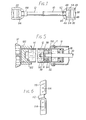
- Figure 1 is a side view of an exerciser in accordance with the invention,
- Figure 2 is a view on a larger scale, partly in section of a handle of the exerciser,
- Figure 3 is a section on line III-III of Figure 2,
- Figure 4 is a section on line IV-IV of Figure 2,
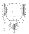
- Figure 5 is a section, on a larger scale, through part of the telescoping cylinders of the exerciser, and
- Figure 6 is a perspective view of an anchor plate for use with the exerciser.
- Referring to the drawings, the exerciser comprises an
outer cylinder 10 and aninner cylinder 12 telescopically received within the outer cylinder, the inner cylinder sliding in aplastics collar 11 fixed to the end of the outer cylinder. Theinner cylinder 12 is closed at both ends to form a chamber 14 (Figure 5), which is partially filled with hydraulic fluid of suitable viscosity. Slidable withinchamber 14 is apiston 16 mounted on the end of apiston rod 20 which extends through a seal in oneend wall 18 of theinner cylinder 12 and is fixed as described below to theend wall 24 ofouter cylinder 10. As described below, thepiston 16 is formed with a number of ports through which the hydraulic fluid passes as the piston moves within thechamber 14, the dimensions of the ports being chosen to provide a suitable range of resistances to relative movement between theouter cylinder 10 andinner cylinder 12. Ahandle 30 is fixed to the outer end ofcylinder 10 and asimilar handle 32 is fixed to the outer end ofcylinder 12. - As shown in Figures 2 to 4, the
handle 30 includes amain frame 42, of moulded plastics, formed in twohalves bolts main frame 42 consists of abase portion 52, twoparallel side members 54 and abridging member 56 extending transversely between the ends of theside members 54. - The
base portion 52 is secured to thecylinder 10 by means of asteel locking piece 58 comprising anannular base 60 which lies against theend wall 24 of thecylinder 10 and twolugs 62 extending at right angles from thebase 60. Thelugs 62 fit intocomplementary slots 64 defined by opposed recesses in the twohalves bores 68 in the handle halves aligned withholes 70 in thelugs 62. The threadedend 72 of thepiston rod 20 passes through anut 74 insidecylinder 10, through theend wall 24 of the cylinder and through the centre ofbase 60 of thelocking piece 58. Alocking nut 76 engages the end of therod 20 to hold the locking piece in position. - Each
side member 54 of thehandle 30 is formed with acylindrical bore 80 housing acompression spring 82. Amovable member 84, extending transversely betweenside members 54, is formed withouter end portions 86 slidable within thebores 80. Eachportion 86 is joined to the main part ofmovable member 84 through aportion 88 of reduced thickness, which extends through aslot 90 formed in thecorresponding side member 54, theslots 90 allowing movement of themovable member 84 towards and away from thebridging member 56 of the handle. - The
springs 82 act between the ends of thebores 80 and theportions 86 ofmovable member 84, to bias themovable member 84 away from thebridging member 56 to the position shown in the drawings. A spring guide in the form of arod 91 extends through each spring and through a bore in theend portion 86 of themember 84. -
Handle 32 is constructed in a similar manner to handle 30. The dimensions of the handles are 30 and 32 such that, when a user holds the exerciser with one hand holding each of the handles, the user can grip themovable member 84 of each handle with his fingers and draw it, by a gripping motion, towards the bridgingmember 56 against the bias of thesprings 82. The user can therefore use the exerciser to exercise the muscles of the hand. - As shown in Figure 5, the
piston 16 consists of a fixedmember 92 welded to thepiston rod 20 and arotatable member 94 which can rotate on thepiston rod 20 whilst being held axially bynut 96.Rotatable member 94 is formed with a number ofbores 98 of different diameters (only two of which are shown) spaced circumferentially around the piston rod, whilst fixedmember 92 has asingle bore 100 of diameter at least as great as the largest diameter bore 98 in the rotatable member. Therotatable member 94 can take up a number of angular positions relative to the fixedmember 92, in each of which one of thebores 98 is aligned with thebore 100, the rotatable member being held in each position by means of a click-stop device, such as one or more ball bearings (not shown) housed in recesses in themovable member 94 and biassed outwards by compression springs into engagement with shallow recesses in the fixedmember 92. Themovable member 94 can be rotated to a selected position by means of a locatingpin 102, fixed at the end ofcylinder 10, which engages in a corresponding hole (not shown) in themember 94 when thepiston 16 is moved to its end position in thecylinder 10. To rotate themovable member 94 from one position to another, thehandles member 94 is in the selected position. The position of themovable member 94 is indicated by the position of aplastics sleeve 108, fixed to theinner cylinder 12 by means of a grub-screw, relative to a fixed point marked on the end of theouter cylinder 10, thesleeve 108 having a number of markings each corresponding to one position of themovable member 94. - When the
handles piston 16 within thecylinder 12, oil in thechamber 14 flows through thebores bore 98, so that by setting themovable member 94 to its different positions, the force required to move thehandles chamber 14 by thepiston rod 20 as the red moves further into thecylinder 12, thechamber 14 is not completely filled with oil, a sufficient volume of air or other compressible gas being retained in the chamber. - Figure 6 shows a
metal anchor plate 110 which can be inserted through thehandle movable member 84 and thebridging portion 56. The anchor plate has acentral portion 112 defining a recess so that when the exerciser is placed vertically, with one handle resting on the ground, theplate 110 fits over thebridging portion 56 of the handle, with the two portions of the plate on either side of thecentral portion 112 engaging the ground on each side of the handle. The user can then place his feet on those two portions of the plate, to hold the handle in position on the ground whilst the other handle is alternately pulled up and pushed down to extend and compress the exerciser. The anchor plate is also provided withscrew holes 114, by means of which it can be attached to a wall or other vertical surface, to enable pushing and pulling exercises to be carried out with one handle fixed to the wall. - It will be appreciated that modifications could be made in the described embodiment. For example, instead of
springs 82 other biasing means could be employed. Thecomposite piston 16 could be replaced by a single piston with a bore of fixed diameter. The invention could also be applied to exercisers other than those using a piston moving in an oil-filled chamber to provide resistance against compression expansion, for example to exercisers of the kind in which the handles are moved together against the force of a compression spring housed within two telscoping tubes.
Claims (6)
1. Exercising apparatus comprising an elongate member capable of compression and extension and having at each end a handle arranged so that a user can grip the handles one in each hand and alternately compress and extend the elongate member, the elongate member including means providing a resistance to such compression and/or extension, in which each handle comprises two members movable towards one another against resilient biasing means and capable of being gripped and moved by the user's hand thereby to exercise the muscles of the hand and fingers.
2. Exercising apparatus as claimed in claim 1, in which each handle comprises two side members extending parallel to the axis of the elongate member, a bridging member extending transversely between the ends of the side members, and a movable member extending transversely between the side members and guided for movement towards and away from the bridging member and biased away from the bridging member by the resilient biasing means.
3. Exercising apparatus as claimed in claim 2, in which the biasing means are springs acting against the movable member.
4. Exercising apparatus as claimed in claim 3, in which each spring is housed in a bore in the associated side member of the handle and engages an end portion of the movable member, each said end portion being connected to a central portion of the movable member by a portion of reduced thickness which extends through an elongate slot in the side member of the handle.
5. Exercising apparatus as claimed in any preceding claim, in which the elongate member comprises two coacial tubes one fitting telescopically within the other with the handles fixed to the ends of the tubes, the inner tube defining a chamber which is filled or partly filled with hdyraulic fluid and which houses a piston connected by a piston rod to the outer tube, the piston having bores or valves through which oil can flow as the piston moves within the chamber but which provide a restriction to the oil flow so that force is needed to move the two cylinders towards and away from one another.
6. Exercising apparatus as claimed in claim 1, in which there is provided an anchor plate adapted to be positioned between the side members of one of the handles.and having a recess shaped to receive the bridging member of the handle so that portions of the anchor plate on each side of the bridging member can lie against a flat surface to enable the handle to be held by the anchor plate against movement away from the surface.
Applications Claiming Priority (2)
| Application Number | Priority Date | Filing Date | Title |
|---|---|---|---|
| GB7942200 | 1979-12-06 | ||
| GB7942200 | 1979-12-06 |
Publications (1)
| Publication Number | Publication Date |
|---|---|
| EP0030833A1 true EP0030833A1 (en) | 1981-06-24 |
Family
ID=10509678
Family Applications (1)
| Application Number | Title | Priority Date | Filing Date |
|---|---|---|---|
| EP80304402A Withdrawn EP0030833A1 (en) | 1979-12-06 | 1980-12-05 | Exercising apparatus |
Country Status (1)
| Country | Link |
|---|---|
| EP (1) | EP0030833A1 (en) |
Cited By (3)
| Publication number | Priority date | Publication date | Assignee | Title |
|---|---|---|---|---|
| FR2605231A2 (en) * | 1985-12-04 | 1988-04-22 | Miccoli Cosimo | HYDRAULIC SYSTEM APPLIED TO MUSCULATION DEVICES |
| EP0521037A4 (en) * | 1990-03-22 | 1994-03-16 | John Charles Thornton | |
| CN107335187A (en) * | 2016-12-24 | 2017-11-10 | 重庆都英科技有限公司 | A kind of safety body-building chest-developer |
Citations (1)
| Publication number | Priority date | Publication date | Assignee | Title |
|---|---|---|---|---|
| US3834696A (en) * | 1973-05-16 | 1974-09-10 | Sam Rubin | Double-acting hydraulic exerciser |
-
1980
- 1980-12-05 EP EP80304402A patent/EP0030833A1/en not_active Withdrawn
Patent Citations (1)
| Publication number | Priority date | Publication date | Assignee | Title |
|---|---|---|---|---|
| US3834696A (en) * | 1973-05-16 | 1974-09-10 | Sam Rubin | Double-acting hydraulic exerciser |
Cited By (3)
| Publication number | Priority date | Publication date | Assignee | Title |
|---|---|---|---|---|
| FR2605231A2 (en) * | 1985-12-04 | 1988-04-22 | Miccoli Cosimo | HYDRAULIC SYSTEM APPLIED TO MUSCULATION DEVICES |
| EP0521037A4 (en) * | 1990-03-22 | 1994-03-16 | John Charles Thornton | |
| CN107335187A (en) * | 2016-12-24 | 2017-11-10 | 重庆都英科技有限公司 | A kind of safety body-building chest-developer |
Similar Documents
| Publication | Publication Date | Title |
|---|---|---|
| US8162808B2 (en) | Compressible curl bar | |
| US5449333A (en) | Bar having O-rings to secure the weight | |
| US4664373A (en) | Device for performing exercises | |
| US5700232A (en) | Exercise apparatus | |
| US3971255A (en) | Exercise apparatus | |
| US3822599A (en) | Exercising device | |
| US3759514A (en) | Resilient push-pull exerciser | |
| US5236407A (en) | Hydraulic exerciser | |
| US7087000B1 (en) | Collarless barbell sleeve | |
| US5788617A (en) | Pectoralis major and upper back exerciser | |
| US6241643B1 (en) | Arm exercising device | |
| US20040018920A1 (en) | Exercise apparatus with sliding pulley | |
| SE438096B (en) | EXERCISE TOOLS WHICH CAN BE PRESSED IN THEIR LENGTH | |
| CA2170720A1 (en) | Exercising apparatus | |
| US5509878A (en) | Resist/assist exerciser and its use | |
| WO1993007934A1 (en) | Hydraulic exercise apparatus | |
| US5250015A (en) | Hydraulic exercise apparatus having a main cylinder and a displacement cylinder | |
| US4211405A (en) | Physical exercising device | |
| US10413771B1 (en) | Exercise systems and methods | |
| EP0030833A1 (en) | Exercising apparatus | |
| GB2064342A (en) | Exercising apparatus | |
| US3741539A (en) | Spring resistant type of exercising device | |
| US20090088304A1 (en) | Exercise device | |
| US5411460A (en) | Modular exercise device with selectable resistance | |
| US5385524A (en) | Exercise device |
Legal Events
| Date | Code | Title | Description |
|---|---|---|---|
| PUAI | Public reference made under article 153(3) epc to a published international application that has entered the european phase |
Free format text: ORIGINAL CODE: 0009012 |
|
| AK | Designated contracting states |
Designated state(s): AT BE CH DE FR GB IT LU NL SE |
|
| STAA | Information on the status of an ep patent application or granted ep patent |
Free format text: STATUS: THE APPLICATION IS DEEMED TO BE WITHDRAWN |
|
| 18D | Application deemed to be withdrawn |
Effective date: 19820531 |
|
| RIN1 | Information on inventor provided before grant (corrected) |
Inventor name: ROLT, ALAN FREDERICK |