EP0520904A1 - Lock with a disconnectable rotor - Google Patents
Lock with a disconnectable rotor Download PDFInfo
- Publication number
- EP0520904A1 EP0520904A1 EP92401808A EP92401808A EP0520904A1 EP 0520904 A1 EP0520904 A1 EP 0520904A1 EP 92401808 A EP92401808 A EP 92401808A EP 92401808 A EP92401808 A EP 92401808A EP 0520904 A1 EP0520904 A1 EP 0520904A1
- Authority
- EP
- European Patent Office
- Prior art keywords
- rotor
- intermediate stator
- key
- lock
- branch
- Prior art date
- Legal status (The legal status is an assumption and is not a legal conclusion. Google has not performed a legal analysis and makes no representation as to the accuracy of the status listed.)
- Granted
Links
Images

Classifications
-
- E—FIXED CONSTRUCTIONS
- E05—LOCKS; KEYS; WINDOW OR DOOR FITTINGS; SAFES
- E05B—LOCKS; ACCESSORIES THEREFOR; HANDCUFFS
- E05B17/00—Accessories in connection with locks
- E05B17/04—Devices for coupling the turning cylinder of a single or a double cylinder lock with the bolt operating member
-
- E—FIXED CONSTRUCTIONS
- E05—LOCKS; KEYS; WINDOW OR DOOR FITTINGS; SAFES
- E05B—LOCKS; ACCESSORIES THEREFOR; HANDCUFFS
- E05B17/00—Accessories in connection with locks
- E05B17/0054—Fraction or shear lines; Slip-clutches, resilient parts or the like for preventing damage when forced or slammed
- E05B17/0058—Fraction or shear lines; Slip-clutches, resilient parts or the like for preventing damage when forced or slammed with non-destructive disengagement
-
- E—FIXED CONSTRUCTIONS
- E05—LOCKS; KEYS; WINDOW OR DOOR FITTINGS; SAFES
- E05B—LOCKS; ACCESSORIES THEREFOR; HANDCUFFS
- E05B15/00—Other details of locks; Parts for engagement by bolts of fastening devices
- E05B15/04—Spring arrangements in locks
- E05B2015/0472—Made of rubber, plastics or the like
Definitions
- the present invention relates generally to a disengageable rotor lock.
- Such a lock consists of a rotor swiveling in a sleeve or intermediate stator, said intermediate stator being able to pivot itself in a fixed body.
- Locking members such as pairs of pistons or flakes cooperate with the rotor and the intermediate stator so as to make them rotationally integral in the absence of a key or in the presence of a non-conforming key and to release the rotor in rotation by report to the intermediate stator when a compliant key is introduced.
- Such a lock further comprises a member for controlling a lock and means for securing the rotor to said control member, the securing means being used only when the rotor turns alone, independently of the intermediate stator.
- Such locks with disengageable rotor have the important advantage, from the point of view of safety, of not being able to be forced into rotation.
- An erasable indexing member may consist of a ball recalled by a spring, sliding in a blind bore of the stator and cooperating with a hole in the body of the lock, as described and shown in document FR-A- 2,583,813.
- Document FR-A-2 631 067 describes such a body indexing consisting of a lever integral in rotation with the intermediate stator provided with a heel, housed in the rest position in a longitudinal groove in the body of the lock, said lever being returned to the intermediate stator by a spring.
- Document EP-A-0410 830 also describes such a member consisting of two diametrically opposite elastic tabs cooperating with recesses in the intermediate stator.
- Such a configuration allows, with two separate parts, to perform the functions of angular indexing and rotor-stator connection.
- a disengageable rotor lock comprising a rotor swiveling in an intermediate stator, itself pivoting in a fixed body, locking members such as flakes or pairs of pistons cooperating with the rotor and the intermediate stator to secure them in rotation in the absence of a key or in the presence of a non-conforming key and release the rotor relative to the intermediate stator after introduction of a conforming key, first erasable indexing means of the intermediate stator relative to the body and second means for strengthening the rotor connection, intermediate stator in the presence of a non-conforming key, characterized in that the first and second means are constituted by at least one elastic tab formed in a material in a recess in the intermediate stator, each elastic tab comprising a circular branch connected to a radial branch.
- the glitter lock shown in particular in FIG. 1 comprises a rotor 11, journalled in an intermediate stator 12, said intermediate stator 12 pivoting in a fixed body 13.
- the rotor 11 has a longitudinal key channel 14, into which radial slots 15 open.
- the intermediate stator 12 has slots longitudinal 16 intended to receive the ends of flakes 17 housed in the radial slots 15.
- the flakes 17 which constitute the locking members between the rotor 11 and the intermediate stator 12 can be replaced by any known locking members such as pairs of pistons, levers etc.
- the entire lock is intended to be fixed for example in a door handle of a motor vehicle 18 by any suitable means.
- the rotor 11 has at one of its ends a lug 19 intended to cooperate with a control member 20 whose axis 21 is secured to an operating lever (not shown) for actuating the lock mechanism.
- a compression spring 22 makes it possible to return the rotor 11 - intermediate stator 12 assembly to the rest position.
- a torsion spring 23 returns the rotor 11 to the rest position after its rotation.
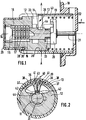
- FIG. 3 describes in more detail the intermediate stator 12 which comprises, on the insertion side of the key, a cylindrical part 25 connected to a cylindrical flange 26 of larger diameter.
- This flange 26 has at its periphery notches 27 intended to receive the fixing lugs 28 of a protective cover 29 (see FIG. 1).
- a central bore 31 passes through the assembly of the intermediate stator and serves as a housing for the rotor 11.
- the rear part 32 of the intermediate stator 12 has a recess 33 providing two flats 34,35.
- the intermediate stator 12 comprises, made of material, two elastic tabs 36 constituting on the one hand first erasable indexing means, on the other hand second means for reinforcing the rotor connection 11, intermediate stator 12 , in the presence of a non-compliant key.
- Each elastic tab 36 comprises a circular branch 37, the outer face 38 of which is eccentric with respect to the inner face 39 of the body 13 (FIG. 2).
- Each circular branch 37 is connected on the one hand to the flats 34, 35 and on the other hand to a radial branch 40 each having an external side with a rounded projection 41.
- the radial branches 40 have a tapering section towards the axis of the intermediate stator so as to constitute, on the side opposite the projection 41, a heel 42.
- each elastic tab 36 cooperates with a longitudinal groove 43 formed in the body 13.
- the rotor 31 In line with the heels 42, the rotor 31 has a housing 44, the role of which will be explained below.
- the elastic tabs 36 In the rest position, or in the event of the introduction of a conforming key, the elastic tabs 36 occupy the position shown in solid lines in FIG. 2: the heels 42 are flush with the external periphery of the rotor 11 and the projections 41 are inside. of the longitudinal groove 43 of the body 13 thus constituting the first erasable indexing means between the intermediate stator 12 and the body 13.
- the locking members 17 are in concordance with the rotor 11, thus disengaging it in rotation from the intermediate stator 12.
- the heels 42 of the elastic tabs are no longer opposite the housing 44 but are flush with the full external periphery of the rotor, which prevents any untimely disengaging, for example when the conforming key is in abutment, at the end of its rotation.
- the locking members 17 keep the rotor 11 integral in rotation with the intermediate stator 12.
- the projections 41 of the elastic tabs 36 escape from the longitudinal groove 43 and come to bear against the internal wall 39 of the body 19. Simultaneously their heels 42 penetrate into the housing 44 of the rotor 11 as shown in dashed lines in FIG. 2 and thus constitute the second means for strengthening the rotational connection of the rotor 11 with the intermediate stator 12. It is therefore the rotor 11 - intermediate stator 12 assembly which pivots in the body 13 preventing any actuation of the lock mechanism.
- first and second means thus formed are particularly simple since they do not require any additional part.
- the two legs 36 could be replaced by a single one, likewise the legs 36 could have a common heel 42 without thereby departing from the scope of the invention.
Abstract
Description
La présente invention concerne d'une manière générale, un verrou à rotor débrayable.The present invention relates generally to a disengageable rotor lock.
Un tel verrou est constitué d'un rotor tourillonnant dans une douille ou stator intermédiaire, ledit stator intermédiaire pouvant lui-même pivoter dans un corps fixe. Des organes de verrouillage tels que couples de pistons ou paillettes coopèrent avec le rotor et le stator intermédiaire de manière à les rendre solidaires en rotation en l'absence de clé ou en présence d'une clé non conforme et à libérer en rotation le rotor par rapport au stator intermédiaire lorsqu'une clé conforme est introduite.Such a lock consists of a rotor swiveling in a sleeve or intermediate stator, said intermediate stator being able to pivot itself in a fixed body. Locking members such as pairs of pistons or flakes cooperate with the rotor and the intermediate stator so as to make them rotationally integral in the absence of a key or in the presence of a non-conforming key and to release the rotor in rotation by report to the intermediate stator when a compliant key is introduced.
Un tel verrou comprend en outre un organe de commande d'une serrure et des moyens de solidarisation du rotor avec ledit organe de commande, les moyens de solidarisation n'étant mis en oeuvre que lorsque le rotor tourne seul, indépendamment du stator intermédiaire.Such a lock further comprises a member for controlling a lock and means for securing the rotor to said control member, the securing means being used only when the rotor turns alone, independently of the intermediate stator.
De tels verrous à rotor débrayable présentent l'avantage important, du point de vue de la sécurité, de ne pas pouvoir être forcés en rotation.Such locks with disengageable rotor have the important advantage, from the point of view of safety, of not being able to be forced into rotation.
En effet, si la bonne clé n'est pas introduite ou si l'on force sur le rotor, le stator intermédiaire est entraîné en rotation par les organes de verrouillage, ce qui rend inopérants les moyens de solidarisation du rotor avec l'organe de commande de la serrure.In fact, if the correct key is not inserted or if the rotor is forced, the intermediate stator is rotated by the locking members, which makes inoperative the means for securing the rotor to the locking member. lock control.
Dans ce type de verrou, il est nécessaire que le stator intermédiaire soit maintenu en position de repos par un organe d'indexation effaçable de manière que, pour une utilisation normale du verrou, l'axe du canal clé ait toujours la même position angulaire.In this type of lock, it is necessary for the intermediate stator to be held in the rest position by an erasable indexing member so that, for normal use of the lock, the axis of the key channel always has the same angular position.
Un organe d'indexation effaçable peut être constitué d'une bille rappelée par un ressort, coulissant dans un alésage borgne du stator et coopérant avec un trou ménagé dans le corps du verrou, comme il est décrit et représenté dans le document FR-A-2 583 813.An erasable indexing member may consist of a ball recalled by a spring, sliding in a blind bore of the stator and cooperating with a hole in the body of the lock, as described and shown in document FR-A- 2,583,813.
Le document FR-A-2 631 067 décrit, un tel organe d'indexation constitué d'un levier solidaire en rotation du stator intermédiaire muni d'un talon, logé en position de repos dans une rainure longitudinale du corps du verrou, ledit levier étant rappelé vers le stator intermédiaire par un ressort.Document FR-A-2 631 067 describes such a body indexing consisting of a lever integral in rotation with the intermediate stator provided with a heel, housed in the rest position in a longitudinal groove in the body of the lock, said lever being returned to the intermediate stator by a spring.
Le document EP-A-0410 830 décrit également un tel organe constitué de deux pattes élastiques diamètralement opposées coopérant avec des évidements du stator intermédiaire.Document EP-A-0410 830 also describes such a member consisting of two diametrically opposite elastic tabs cooperating with recesses in the intermediate stator.
Dans un verrou du type précité, il est également nécessaire, lorsqu'une clé non conforme est introduite, de renforcer la liaison rotor-stator intermédiaire de manière à ce que ces deux éléments soient entraînés en rotation.In a lock of the aforementioned type, it is also necessary, when a non-conforming key is introduced, to reinforce the intermediate rotor-stator connection so that these two elements are driven in rotation.
Une telle liaison est illustrée dans le document FR-A-2 620 755 par un pion dont l'extrémité pénètre dans le rotor lorsqu'une clé non conforme est introduite et qui est rappelé en position de repos par un ressort.Such a connection is illustrated in document FR-A-2 620 755 by a pin, the end of which enters the rotor when a non-conforming key is introduced and which is returned to the rest position by a spring.
Une telle configuration permet, avec deux pièces distinctes, de réaliser les fonctions d'indexation angulaire et de liaison rotor-stator.Such a configuration allows, with two separate parts, to perform the functions of angular indexing and rotor-stator connection.
Néanmoins, ces fonctions nécessitent des pièces complémentaires dont la mise en place est souvent délicate, ce qui entraîne une augmentation de coût incompatible avec les nécessités économiques d'une fabrication en grande série comme c'est le cas, en particulier, dans le domaine automobile.However, these functions require additional parts, the installation of which is often difficult, which leads to an increase in cost incompatible with the economic necessities of mass production as is the case, in particular, in the automotive field. .
La présente invention résout ces problèmes et propose à cet effet un verrou à rotor débrayable comprenant un rotor tourillonnant dans un stator intermédiaire, lui-même pivotant dans un corps fixe, des organes de verrouillage tels que paillettes ou couples de pistons coopérant avec le rotor et le stator intermédiaire pour les solidariser en rotation en l'absence de clé ou en présence d'une clé non conforme et libérer le rotor par rapport au stator intermédiaire après introduction d'une clé conforme, des premiers moyens d'indexation effaçables du stator intermédiaire par rapport au corps et des seconds moyens de renforcement de la liaison rotor, stator intermédiaire en présence d'une clé non conforme, caractérisé en ce que les premiers et seconds moyens sont constitués par au moins une patte élastique ménagée de matière dans un évidement du stator intermédiaire, chaque patte élastique comprenant une branche circulaire raccordée à une branche radiale.The present invention solves these problems and proposes for this purpose a disengageable rotor lock comprising a rotor swiveling in an intermediate stator, itself pivoting in a fixed body, locking members such as flakes or pairs of pistons cooperating with the rotor and the intermediate stator to secure them in rotation in the absence of a key or in the presence of a non-conforming key and release the rotor relative to the intermediate stator after introduction of a conforming key, first erasable indexing means of the intermediate stator relative to the body and second means for strengthening the rotor connection, intermediate stator in the presence of a non-conforming key, characterized in that the first and second means are constituted by at least one elastic tab formed in a material in a recess in the intermediate stator, each elastic tab comprising a circular branch connected to a radial branch.
Selon d'autres caractéristiques de l'invention :
- les premiers moyens sont constitués par une extrémité de la branche radiale présentant une saillie destinée à coopérer avec une rainure longitudinale ménagée dans le corps.
- les seconds moyens sont constitués par une extrémité de la branche radiale opposée à la saillie présentant un talon destiné à coopérer avec un logement ménagé dans le rotor.
- the first means consist of one end of the radial branch having a projection intended to cooperate with a longitudinal groove formed in the body.
- the second means consist of one end of the radial branch opposite the projection having a heel intended to cooperate with a housing formed in the rotor.
La présente invention sera mieux comprise à la lecture de la description qui va suivre en regard des dessins annexés dans lesquels :
- la figure 1 est une vue schématique en coupe axiale d'un verrou selon l'invention ;
- la figure 2 est une vue en coupe suivant la ligne A-A de la figure 1 ;
- la figure 3 est une vue en perspective à échelle agrandie suivant la flèche F de la figure 1 d'un stator intermédiaire destiné à équiper le verrou.
- Figure 1 is a schematic view in axial section of a lock according to the invention;
- Figure 2 is a sectional view along line AA of Figure 1;
- Figure 3 is a perspective view on an enlarged scale along the arrow F of Figure 1 of an intermediate stator intended to equip the lock.
Le verrou à paillettes représenté en particulier à la figure 1 comprend un rotor 11, tourillonnant dans un stator intermédiaire 12, ledit stator intermédiaire 12 pivotant dans un corps fixe 13.The glitter lock shown in particular in FIG. 1 comprises a
Le rotor 11 comporte un canal de clé longitudinal 14, dans lequel débouchent des fentes radiales 15.The
Le stator intermédiaire 12 comporte des fentes longitudinales 16 destinées à recevoir les extrémités de paillettes 17 logées dans les fentes radiales 15.The
En l'absence de clé ou en présence d'une clé non conforme, les extrémités des paillettes 17 ne sont pas dans l'enveloppe du rotor 11, qui est ainsi solidaire en rotation du stator intermédiaire 12.In the absence of a key or in the presence of a non-conforming key, the ends of the
Bien entendu, les paillettes 17 qui constituent les organes de verrouillage entre le rotor 11 et le stator intermédiaire 12 peuvent être remplacés par tous organes de verrouillage connus tels que couples de pistons, leviers etc.Of course, the
L'ensemble du verrou est destiné à être fixé par exemple dans une poignée de portière de véhicule automobile 18 par tout moyen approprié.The entire lock is intended to be fixed for example in a door handle of a
Le rotor 11 comporte à l'une de ses extrémités un ergot 19 destiné à coopérer avec un organe de commande 20 dont l'axe 21 est solidaire d'un levier de manoeuvre (non représenté) pour actionner le mécanisme de serrure.The
Tous ces éléments ne faisant pas partie de la présente invention ne seront pas décrits plus en détail.All these elements not forming part of the present invention will not be described in more detail.
Un ressort de compression 22 permet de ramener en position de repos l'ensemble rotor 11 - stator intermédiaire 12. Un ressort de torsion 23 ramène le rotor 11 en position de repos après sa rotation.A
On se réfère maintenant à la figure 3 pour décrire plus en détail le stator intermédiaire 12 qui comprend côté introduction de la clé, une partie cylindrique 25 reliée à une collerette cylindrique 26 de plus grand diamètre.Reference is now made to FIG. 3 to describe in more detail the
Cette collerette 26 comporte à sa périphérie des encoches 27 destinées à recevoir les pattes de fixation 28 d'un capot de protection 29 (voir figure 1).This
Les extrémités de ces pattes 28 viennent se loger dans un évidement 30 adjacent à la collerette 26.The ends of these
Un alésage central 31 traverse l'ensemble du stator intermédiaire et sert de logement au rotor 11.A
La partie arrière 32 du stator intermédiaire 12 comporte un évidement 33 ménageant deux méplats 34,35.The
Suivant l'invention, le stator intermédiaire 12 comporte, ménagé de matière, deux pattes élastiques 36 constituant d'une part des premiers moyens d'indexation effaçables, d'autre part des seconds moyens de renforcement de la liaison rotor 11, stator intermédiaire 12, en présence d'une clé non conforme.According to the invention, the
Chaque patte élastique 36 comprend une branche circulaire 37, dont la face extérieure 38 est excentrée par rapport à la face interne 39 du corps 13 (figure 2).Each
Chaque branche circulaire 37 se raccorde d'une part aux méplats 34,35 et d'autre part à une branche radiale 40 comportant chacune côté extérieur une saillie arrondie 41.Each
Les branches radiales 40 présentent une section dégressive vers l'axe du stator intermédiaire de manière à constituer du côté opposé à la saillie 41 un talon 42.The
Ainsi qu'on le voit, en particulier figure 2, les saillies 41 de chaque patte élastique 36 coopèrent avec une rainure longitudinale 43 ménagée dans le corps 13.As can be seen, in particular in FIG. 2, the
Au droit des talons 42, le rotor 31 présente un logement 44, dont le rôle sera explicité ci-après.In line with the
Dans la position de repos, ou en cas d'introduction d'une clé conforme les pattes élastiques 36 occupent la position représentée en traits pleins figure 2 : les talons 42 affleurent la périphérie externe du rotor 11 et les saillies 41 sont à l'intérieur de la rainure longitudinale 43 du corps 13 constituant ainsi les premiers moyens d'indexation effaçables entre le stator intermédiaire 12 et le corps 13.In the rest position, or in the event of the introduction of a conforming key, the
Lorsque la clé conforme est introduite, les organes de verrouillage 17 sont en concordance avec le rotor 11, le désolidarisant ainsi en rotation du stator intermédiaire 12.When the conforming key is introduced, the
Dans cette configuration, les talons 42 des pattes élastiques ne sont plus en vis-à-vis du logement 44 mais affleurent la périphérie externe pleine du rotor, ce qui empêche tout débrayage intempestif, par exemple lorsque la clé conforme est en butée, à la fin de sa rotation.In this configuration, the
Le fait de tourner la clé entraîne en rotation le rotor 11 qui par son ergot 19 entraîne à son tour l'organe de commande 21 et donc le mécanisme de serrure.Turning the key rotates the
Si une clé non conforme est introduite dans le rotor 11, les organes de verrouillage 17 maintiennent le rotor 11 solidaire en rotation du stator intermédiaire 12. Lorsque l'on cherche à forcer en rotation l'ensemble rotor 11 - stator intermédiaire 12, les saillies 41 des pattes élastiques 36 échappent à la rainure longitudinale 43 et viennent en appui contre la paroi interne 39 du corps 19. Simultanément leurs talons 42 pénètrent dans le logement 44 du rotor 11 ainsi qu'il est représenté en traits mixtes sur la figure 2 et constituent ainsi les seconds moyens de renforcement de la liaison en rotation du rotor 11 avec le stator intermédiaire 12. C'est donc l'ensemble rotor 11 - stator intermédiaire 12 qui tourillonne dans le corps 13 empêchant tout actionnement du mécanisme de serrure.If a non-conforming key is introduced into the
On appréciera que les premiers et seconds moyens ainsi constitués sont particulièrement simples puisqu'ils ne nécessitent aucune pièce complémentaire.It will be appreciated that the first and second means thus formed are particularly simple since they do not require any additional part.
Bien entendu, la présente invention n'est pas limité aux formes de réalisations décrites ou représentées mais englobe toute variante que l'homme de l'art pourrait y apporter.Of course, the present invention is not limited to the embodiments described or shown but encompasses any variant that a person skilled in the art could make.
En particulier, les deux pattes 36 pourraient être remplacées par une seule, de même les pattes 36 pourraient présenter un talon commun 42 sans pour cela sortir du cadre de l'invention.In particular, the two
Claims (6)
Applications Claiming Priority (2)
| Application Number | Priority Date | Filing Date | Title |
|---|---|---|---|
| FR9107997A FR2678312B1 (en) | 1991-06-27 | 1991-06-27 | RELEASABLE ROTOR LOCK. |
| FR9107997 | 1991-06-27 |
Publications (2)
| Publication Number | Publication Date |
|---|---|
| EP0520904A1 true EP0520904A1 (en) | 1992-12-30 |
| EP0520904B1 EP0520904B1 (en) | 1994-11-02 |
Family
ID=9414405
Family Applications (1)
| Application Number | Title | Priority Date | Filing Date |
|---|---|---|---|
| EP19920401808 Expired - Lifetime EP0520904B1 (en) | 1991-06-27 | 1992-06-25 | Lock with a disconnectable rotor |
Country Status (4)
| Country | Link |
|---|---|
| EP (1) | EP0520904B1 (en) |
| DE (1) | DE69200617T2 (en) |
| ES (1) | ES2065760T3 (en) |
| FR (1) | FR2678312B1 (en) |
Cited By (8)
| Publication number | Priority date | Publication date | Assignee | Title |
|---|---|---|---|---|
| EP0611860A1 (en) * | 1993-02-18 | 1994-08-24 | YMOS AKTIENGESELLSCHAFT Industrieprodukte | Locking device |
| FR2705387A1 (en) * | 1993-05-21 | 1994-11-25 | Valeo Securite Habitacle | Disengageable rotor lock. |
| DE4330980A1 (en) * | 1993-09-13 | 1995-03-16 | Valeo Deutschland Gmbh & Co | Device for a locking stop between two parts, in particular for a motor vehicle lock |
| FR2721646A1 (en) * | 1994-06-24 | 1995-12-29 | Valeo Securite Habitacle | Declutching control mechanism for vehicle hatchback lock |
| EP0833023A2 (en) * | 1996-09-25 | 1998-04-01 | VALEO GmbH & Co Schliesssysteme KG | Lock cylinder with an overload clutch device |
| FR2762640A1 (en) * | 1997-04-29 | 1998-10-30 | Antivols Simplex Sa | Car lock with improved bi-stable spring |
| WO2007082569A1 (en) * | 2006-01-18 | 2007-07-26 | Huf Hülsbeck & Fürst Gmbh & Co. Kg | Locking device for functions which can be carried out in particular on vehicles |
| FR3086317A1 (en) * | 2018-09-26 | 2020-03-27 | U-Shin France | FUSE-RESISTANT MEANS |
Families Citing this family (3)
| Publication number | Priority date | Publication date | Assignee | Title |
|---|---|---|---|---|
| DE29517204U1 (en) * | 1995-10-31 | 1997-03-06 | Pollerhoff Holger | Lock with very high protection against drilling |
| DE19639251C1 (en) * | 1996-09-25 | 1997-12-18 | Valeo Gmbh & Co Schliessyst Kg | Lock cylinder with rotatably arranged cylinder core in housing |
| EP1193359B1 (en) | 2000-09-27 | 2005-09-21 | Valeo Sicherheitssysteme GmbH | Closure device |
Citations (2)
| Publication number | Priority date | Publication date | Assignee | Title |
|---|---|---|---|---|
| FR2620755A2 (en) * | 1984-01-31 | 1989-03-24 | Dupart Jean | Lock with an attached safety unit arranged to prevent its fraudulent opening |
| EP0410830A1 (en) * | 1989-07-24 | 1991-01-30 | Vachette | Safety lock with disconnectable stator |
-
1991
- 1991-06-27 FR FR9107997A patent/FR2678312B1/en not_active Expired - Fee Related
-
1992
- 1992-06-25 ES ES92401808T patent/ES2065760T3/en not_active Expired - Lifetime
- 1992-06-25 DE DE1992600617 patent/DE69200617T2/en not_active Expired - Fee Related
- 1992-06-25 EP EP19920401808 patent/EP0520904B1/en not_active Expired - Lifetime
Patent Citations (2)
| Publication number | Priority date | Publication date | Assignee | Title |
|---|---|---|---|---|
| FR2620755A2 (en) * | 1984-01-31 | 1989-03-24 | Dupart Jean | Lock with an attached safety unit arranged to prevent its fraudulent opening |
| EP0410830A1 (en) * | 1989-07-24 | 1991-01-30 | Vachette | Safety lock with disconnectable stator |
Cited By (13)
| Publication number | Priority date | Publication date | Assignee | Title |
|---|---|---|---|---|
| EP0611860A1 (en) * | 1993-02-18 | 1994-08-24 | YMOS AKTIENGESELLSCHAFT Industrieprodukte | Locking device |
| FR2705387A1 (en) * | 1993-05-21 | 1994-11-25 | Valeo Securite Habitacle | Disengageable rotor lock. |
| EP0631028A1 (en) * | 1993-05-21 | 1994-12-28 | Valeo Securite Habitacle | Lock with disconnectable rotor |
| DE4330980A1 (en) * | 1993-09-13 | 1995-03-16 | Valeo Deutschland Gmbh & Co | Device for a locking stop between two parts, in particular for a motor vehicle lock |
| FR2721646A1 (en) * | 1994-06-24 | 1995-12-29 | Valeo Securite Habitacle | Declutching control mechanism for vehicle hatchback lock |
| EP0833023A2 (en) * | 1996-09-25 | 1998-04-01 | VALEO GmbH & Co Schliesssysteme KG | Lock cylinder with an overload clutch device |
| EP0833023A3 (en) * | 1996-09-25 | 1998-09-16 | VALEO GmbH & Co Schliesssysteme KG | Lock cylinder with an overload clutch device |
| FR2762640A1 (en) * | 1997-04-29 | 1998-10-30 | Antivols Simplex Sa | Car lock with improved bi-stable spring |
| WO2007082569A1 (en) * | 2006-01-18 | 2007-07-26 | Huf Hülsbeck & Fürst Gmbh & Co. Kg | Locking device for functions which can be carried out in particular on vehicles |
| CN101360879B (en) * | 2006-01-18 | 2011-12-14 | 胡夫休尔斯贝克及福尔斯特公司 | Locking device for functions which can be carried out in particular on vehicles |
| US8099987B2 (en) | 2006-01-18 | 2012-01-24 | Huf Hülsbeck & Fürst Gmbh & Co. Kg | Locking device for functions which can be carried out in particular on vehicles |
| FR3086317A1 (en) * | 2018-09-26 | 2020-03-27 | U-Shin France | FUSE-RESISTANT MEANS |
| EP3628798A1 (en) * | 2018-09-26 | 2020-04-01 | U-Shin France | Breakable means for preventing removal |
Also Published As
| Publication number | Publication date |
|---|---|
| DE69200617D1 (en) | 1994-12-08 |
| EP0520904B1 (en) | 1994-11-02 |
| FR2678312A1 (en) | 1992-12-31 |
| ES2065760T3 (en) | 1995-02-16 |
| FR2678312B1 (en) | 1995-09-15 |
| DE69200617T2 (en) | 1995-03-23 |
Similar Documents
| Publication | Publication Date | Title |
|---|---|---|
| EP0334704B1 (en) | Improved quick-release bayonet coupling | |
| EP1957734B1 (en) | Releasable lock for a motor vehicle lock mechanism | |
| EP0520904B1 (en) | Lock with a disconnectable rotor | |
| EP1994243B1 (en) | Self-disengaging lock for a car lock mechanism | |
| EP1314856A1 (en) | Device for locking blades in a disk groove | |
| WO2006092371A1 (en) | Releasable lock for a motor vehicle locking system | |
| EP1863986A1 (en) | Disengageable lock for motor vehicle locking system | |
| EP0647752A2 (en) | Disconnectable lock for cars or the like | |
| EP2614201B1 (en) | Bolt lock for a motor vehicle lock system | |
| FR2776325A1 (en) | IMPROVED AXIAL RELEASE LOCK FOR A MOTOR VEHICLE LOCK MECHANISM | |
| FR2614921A1 (en) | Device for safety against tearing out or pushing in a part which is fitted around another part, and assembly forming a safety lock equipped with this device | |
| EP0571249B1 (en) | Bolt with disconnectable rotor, especially for a motor vehicle lock | |
| EP1026343A1 (en) | Lock with a two part fixed lock body | |
| FR2728929A1 (en) | Lock cylinder mechanism with housing contg. closure | |
| EP0628681B1 (en) | Device implemented by assembly of a lock with its cam actuator | |
| EP0902138B1 (en) | Lock cylinder and key for such a lock cylinder | |
| FR2700355A1 (en) | Closing device | |
| EP0940529A1 (en) | Double plug security cylinder | |
| EP0869236B1 (en) | Safety cylinder operable from one side even when a key is inserted in the opposite side | |
| FR2893063A1 (en) | PUMP LOCK WITH PIN AND ASSOCIATED KEY. | |
| EP0880155B1 (en) | Electric lock controlled by a switch which can be inhibited | |
| FR2705387A1 (en) | Disengageable rotor lock. | |
| EP0457633A1 (en) | Device for fastening of a lock in a door handle, especially the handle of a vehicle door | |
| FR2735514A1 (en) | Steel cylindrical spring lock with brass keyhole | |
| FR2721646A1 (en) | Declutching control mechanism for vehicle hatchback lock |
Legal Events
| Date | Code | Title | Description |
|---|---|---|---|
| PUAI | Public reference made under article 153(3) epc to a published international application that has entered the european phase |
Free format text: ORIGINAL CODE: 0009012 |
|
| AK | Designated contracting states |
Kind code of ref document: A1 Designated state(s): DE ES FR GB IT |
|
| 17P | Request for examination filed |
Effective date: 19930507 |
|
| 17Q | First examination report despatched |
Effective date: 19940301 |
|
| GRAA | (expected) grant |
Free format text: ORIGINAL CODE: 0009210 |
|
| ITF | It: translation for a ep patent filed |
Owner name: SOCIETA' ITALIANA BREVETTI S.P.A. |
|
| AK | Designated contracting states |
Kind code of ref document: B1 Designated state(s): DE ES FR GB IT |
|
| GBT | Gb: translation of ep patent filed (gb section 77(6)(a)/1977) |
Effective date: 19941108 |
|
| REF | Corresponds to: |
Ref document number: 69200617 Country of ref document: DE Date of ref document: 19941208 |
|
| REG | Reference to a national code |
Ref country code: ES Ref legal event code: FG2A Ref document number: 2065760 Country of ref document: ES Kind code of ref document: T3 |
|
| PLBE | No opposition filed within time limit |
Free format text: ORIGINAL CODE: 0009261 |
|
| STAA | Information on the status of an ep patent application or granted ep patent |
Free format text: STATUS: NO OPPOSITION FILED WITHIN TIME LIMIT |
|
| 26N | No opposition filed | ||
| PGFP | Annual fee paid to national office [announced via postgrant information from national office to epo] |
Ref country code: GB Payment date: 19960529 Year of fee payment: 5 |
|
| PGFP | Annual fee paid to national office [announced via postgrant information from national office to epo] |
Ref country code: ES Payment date: 19960611 Year of fee payment: 5 |
|
| PGFP | Annual fee paid to national office [announced via postgrant information from national office to epo] |
Ref country code: DE Payment date: 19960812 Year of fee payment: 5 |
|
| PGFP | Annual fee paid to national office [announced via postgrant information from national office to epo] |
Ref country code: FR Payment date: 19970616 Year of fee payment: 6 |
|
| PG25 | Lapsed in a contracting state [announced via postgrant information from national office to epo] |
Ref country code: GB Free format text: LAPSE BECAUSE OF NON-PAYMENT OF DUE FEES Effective date: 19970625 |
|
| PG25 | Lapsed in a contracting state [announced via postgrant information from national office to epo] |
Ref country code: ES Free format text: LAPSE BECAUSE OF NON-PAYMENT OF DUE FEES Effective date: 19970626 |
|
| GBPC | Gb: european patent ceased through non-payment of renewal fee |
Effective date: 19970625 |
|
| PG25 | Lapsed in a contracting state [announced via postgrant information from national office to epo] |
Ref country code: DE Free format text: LAPSE BECAUSE OF NON-PAYMENT OF DUE FEES Effective date: 19980303 |
|
| PG25 | Lapsed in a contracting state [announced via postgrant information from national office to epo] |
Ref country code: FR Free format text: LAPSE BECAUSE OF NON-PAYMENT OF DUE FEES Effective date: 19990226 |
|
| REG | Reference to a national code |
Ref country code: FR Ref legal event code: ST |
|
| REG | Reference to a national code |
Ref country code: ES Ref legal event code: FD2A Effective date: 20000503 |
|
| PG25 | Lapsed in a contracting state [announced via postgrant information from national office to epo] |
Ref country code: IT Free format text: LAPSE BECAUSE OF NON-PAYMENT OF DUE FEES;WARNING: LAPSES OF ITALIAN PATENTS WITH EFFECTIVE DATE BEFORE 2007 MAY HAVE OCCURRED AT ANY TIME BEFORE 2007. THE CORRECT EFFECTIVE DATE MAY BE DIFFERENT FROM THE ONE RECORDED. Effective date: 20050625 |