EP2614201B1 - Bolt lock for a motor vehicle lock system - Google Patents
Bolt lock for a motor vehicle lock system Download PDFInfo
- Publication number
- EP2614201B1 EP2614201B1 EP11788028.6A EP11788028A EP2614201B1 EP 2614201 B1 EP2614201 B1 EP 2614201B1 EP 11788028 A EP11788028 A EP 11788028A EP 2614201 B1 EP2614201 B1 EP 2614201B1
- Authority
- EP
- European Patent Office
- Prior art keywords
- stator
- cover
- rotor
- lock according
- lock
- Prior art date
- Legal status (The legal status is an assumption and is not a legal conclusion. Google has not performed a legal analysis and makes no representation as to the accuracy of the status listed.)
- Active
Links
- 230000000903 blocking effect Effects 0.000 claims description 4
- 230000002093 peripheral effect Effects 0.000 claims description 4
- 229910000831 Steel Inorganic materials 0.000 claims description 3
- 239000010959 steel Substances 0.000 claims description 3
- 208000031968 Cadaver Diseases 0.000 description 2
- 229910000842 Zamak Inorganic materials 0.000 description 2
- 238000012550 audit Methods 0.000 description 2
- 238000002788 crimping Methods 0.000 description 2
- 238000004519 manufacturing process Methods 0.000 description 2
- 239000000463 material Substances 0.000 description 2
- RYGMFSIKBFXOCR-UHFFFAOYSA-N Copper Chemical compound [Cu] RYGMFSIKBFXOCR-UHFFFAOYSA-N 0.000 description 1
- FYYHWMGAXLPEAU-UHFFFAOYSA-N Magnesium Chemical compound [Mg] FYYHWMGAXLPEAU-UHFFFAOYSA-N 0.000 description 1
- HCHKCACWOHOZIP-UHFFFAOYSA-N Zinc Chemical compound [Zn] HCHKCACWOHOZIP-UHFFFAOYSA-N 0.000 description 1
- 239000000956 alloy Substances 0.000 description 1
- 229910045601 alloy Inorganic materials 0.000 description 1
- XAGFODPZIPBFFR-UHFFFAOYSA-N aluminium Chemical compound [Al] XAGFODPZIPBFFR-UHFFFAOYSA-N 0.000 description 1
- 229910052782 aluminium Inorganic materials 0.000 description 1
- 230000000295 complement effect Effects 0.000 description 1
- 229910052802 copper Inorganic materials 0.000 description 1
- 239000010949 copper Substances 0.000 description 1
- 238000003780 insertion Methods 0.000 description 1
- 230000037431 insertion Effects 0.000 description 1
- 229910052749 magnesium Inorganic materials 0.000 description 1
- 239000011777 magnesium Substances 0.000 description 1
- 230000000717 retained effect Effects 0.000 description 1
- 229910052725 zinc Inorganic materials 0.000 description 1
- 239000011701 zinc Substances 0.000 description 1
Images

Classifications
-
- E—FIXED CONSTRUCTIONS
- E05—LOCKS; KEYS; WINDOW OR DOOR FITTINGS; SAFES
- E05B—LOCKS; ACCESSORIES THEREFOR; HANDCUFFS
- E05B15/00—Other details of locks; Parts for engagement by bolts of fastening devices
- E05B15/16—Use of special materials for parts of locks
- E05B15/1614—Use of special materials for parts of locks of hard materials, to prevent drilling
-
- E—FIXED CONSTRUCTIONS
- E05—LOCKS; KEYS; WINDOW OR DOOR FITTINGS; SAFES
- E05B—LOCKS; ACCESSORIES THEREFOR; HANDCUFFS
- E05B17/00—Accessories in connection with locks
- E05B17/20—Means independent of the locking mechanism for preventing unauthorised opening, e.g. for securing the bolt in the fastening position
- E05B17/2084—Means to prevent forced opening by attack, tampering or jimmying
-
- E—FIXED CONSTRUCTIONS
- E05—LOCKS; KEYS; WINDOW OR DOOR FITTINGS; SAFES
- E05B—LOCKS; ACCESSORIES THEREFOR; HANDCUFFS
- E05B9/00—Lock casings or latch-mechanism casings ; Fastening locks or fasteners or parts thereof to the wing
- E05B9/04—Casings of cylinder locks
-
- E—FIXED CONSTRUCTIONS
- E05—LOCKS; KEYS; WINDOW OR DOOR FITTINGS; SAFES
- E05B—LOCKS; ACCESSORIES THEREFOR; HANDCUFFS
- E05B17/00—Accessories in connection with locks
- E05B17/0004—Lock assembling or manufacturing
Definitions
- the invention relates to a lock for a motor vehicle locking system. More particularly, the invention relates to a rotary electrical switch lock for a motor vehicle lock, but can also be applied to any lock for a motor vehicle.
- a bayonet type mount is also known from EP 1 026 343 .
- the present invention aims to remedy this problem by proposing a lock according to claim 1.
- the cover can thus be mounted manually on the stator so that the assembly does not require any specific tool or mounting station. This results in a significant decrease in production and assembly costs.
- said securing means consists of at least one longitudinal interlocking groove with a rib carried by the front face of the stator.
- said part forms an intermediate rotor cover, in the form of an open-bottomed cup, and comprises a peripheral annular flange comprising at least one resilient lug inclined forwardly in the rest position, forming said locking means, and intended for each cooperate with a groove carried by the rear face of said cover, in said assembled position.
- said annular flange of said intermediate cover comprises at least one said longitudinal interlocking groove with a rib carried by the front face of the stator, forming said securing means.
- Said piece may be steel.
- said cover is fixed to said stator by a bayonet mounting forming said anti-tearing means for axially retaining said rotor in said stator.
- the stator has a rib of general plane perpendicular to the longitudinal axis of the lock and the cover has a corresponding bayonet mounting hook.
- the latch may further include a longitudinal play retrofit member of said cover on said stator.
- Said play-catching element may have a generally strip-like shape and comprises means for assembling said stator and said cover.
- Said catch-up element may have a longitudinal tab abutting against said cover.
- Said catch-up element may be made of plastic.
- the front face of the lock is designated by the end of the lock accessible by the user from outside the motor vehicle.
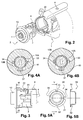
- the figures 1 , 2 and 3 illustrate an insert lockable lock, intended to be mounted in a motor vehicle to secure the direction.
- the antitheft device comprises a receiving body, 1, which is an antitheft body according to the illustrated embodiment, having a first portion in which are integrated locking means for blocking a movable element of the direction (not visible) .
- the antitheft body 1 is also provided with a second portion inside which a latch 2 is intended to be inserted and secured.
- the latch 2 comprises a stator 3 inside which a rotor 4 is mounted to control the implementation of the locking means, via a connecting element (not shown).
- the connecting element has a shaped end so as to be able to fit into a cavity corresponding to the rear of the latch 2 and thus cooperate by driving with the rotor part 4 of the latch 2.
- the rotor 4 is able to be rotatable along the longitudinal axis II inside the stator 3 when the key according to the latch 2 is inserted into the rotor 4 by the keyway 6 provided at the front end. of the rotor 4, so as to unlock the locking system of the motor vehicle.
- rotor designates very generally any subassembly comprising a rotor body through which radial slots are formed capable of receiving flakes which are assembled in radial translation and which are coupled to return springs permanently driving them into protruding positions with respect to the rotor body.
- the latch stator 3 furthermore has a fastening means to the antitheft body 1, for securing the latch 2 with the antitheft body 1.
- this fastening means has an elastic stud 8, for spring-loaded example, implanted on the surface of the stator 3 of the latch 2, cooperating with a corresponding orifice 9, of substantially complementary shape to the stud 8, formed inside the second portion of the antitheft body 1.
- the latch 2 comprises a cover 10 intended to be fixed on the front face of the stator 3.
- the cover 10 has a circular opening 14 to make accessible the key inlet 6 formed at the front end of the rotor 4.
- the cover 10 is made in a material resistant to tearing, for example Zamak type material, Zamak being an alloy based on zinc, aluminum and magnesium with sometimes copper.
- the latch 2 is located in the antitheft body 1 so that the keyway 6 is accessible from outside the motor vehicle.
- the lock 2 comprises an anti-tearing means carried by the cover 10 and the stator 3 to fix the cover 10 to the stator 3 and axially retain the rotor 4 in the stator 3.
- the presence of an anti-pullout means is essential to ensure the integrity of the rotor 4 of the lock 2, in particular with respect to possible attempts of break-in by tearing or breaking of the rotor 4.
- the anti-tearing means is configured to axially block the cover 10 on the stator 3 by positioning the cover 10 on the stator 3 and its subsequent pivoting on said stator 3 in the assembled position shown in FIG. figure 1D .
- the assembly can thus be performed manually so that no specific tool or mounting station is necessary. This results in a significant decrease in production and assembly costs.
- the antitheft body 1 comprises an anti-unscrewing means of the cover 10 on the stator 3.
- the cover 10 is fixed to the stator 3 by a bayonet type mounting, that is to say that the cover 10 is placed on the stator 3 and is pivoted to be retained in axial locking position .
- the bayonet mount forms an anti-tearing means, able to block, in axial translation, the rotor 4 inside the stator 3 when the lock 2 is fixed inside the lock 1.
- the holding of the lock face the driving or tearing of the rotor is thus increased by the bayonet type mounting which allows a better resistance to tearing.
- the stator 3 has a rib 22 of general plane perpendicular to the longitudinal axis II and the edge of the cover 10 has a corresponding hook 23.
- the hook 23 cooperates with the rib 22 to axially retain the cover 10 .
- the cover comprises a longitudinal rib 24 anti-unwinding intended to cooperate with a housing 32 formed near the mouth of the body of the lock 1.
- the latch 2 further comprises a longitudinal play compensator 15 made of plastic.
- This play-catching element makes it possible to make up any games that may exist between the cover 10 and the latch stator 3 and thus eliminate the noise caused by a relative movement between the cover 10 and the stator 3 during the transport of the lock 2 on the vehicle assembly line and once mounted in the lock.
- the play-catching element 15 has, for example, a generally strip-like shape and comprises means of assembly to the stator 3.
- the play-catching element 15 may be snap-fastened to the latch stator 3. It comprises an elastic bridge 18, for example, formed by a curved strip, to make up the play tolerances, a longitudinal lug 16 carried by this element abutting against the cache.
- the lock also comprises means for locking the cover 10 in rotation, consisting of a part 30 interposed between the cover 10 and the front face of the stator 3.
- this piece 30 and cup-shaped open bottom and is an intermediate cache visible on the Figures 1A and 1B is represented alone on the Figures 5A and 5B .
- This piece 30 then also has a tamper-proof function of the rotor, in addition to its locking function in rotation of the cover 10, with its open front wall or open bottom 30A which partially covers the front face of the rotor.
- This intermediate cap 30 of cylindrical shape and advantageously made of steel, possibly stainless, comprises means for securing in rotation with the front face of the stator 3 and a means for locking in rotation of the active cover 10 in the assembled position shown in the Figures 1D and 3 .
- the intermediate cover comprises a peripheral annular flange 31 comprising at least one resilient lug forward 32, 33 in the rest position, forming this locking means, and intended to cooperate with grooves 10A, 10B visible on the Figures 4A and 4B and carried by the rear face of the cover 10, in said assembled position.
- these tabs are two in number and the corresponding grooves.
- the annular flange 31 of the intermediate cover comprises at least one groove, here two grooves 34, 35, longitudinal interlocking with a rib, here two ribs 36, 37, carried (es) by the front face of the stator, forming the means of joining.
- the assembly of a lock 2 according to the invention is carried out as follows.
- the intermediate cover 30 is disposed on the front face of the stator 3, by interlocking the ribs 36, 37 of the latter in the grooves 34, 35 carried by the intermediate cover. In this position, the elastic tabs 32, 33 are in the rest position, inclined forwardly.
- the cover 10 is then applied to this intermediate cover 30, as illustrated on the figure 1C , the resilient tabs 32, 33 being compressed and urged in a non-inclined position as illustrated in FIG. Figure 4A and the hook 23 of the cover 10 being arranged in front of the rib 22 of the stator 3.
- the cover is finally pivoted to engage the hook 23 on the rib 22, as shown in FIG. figure 1D where the lock is in the assembled position.
- the elastic tabs 32, 33 of the intermediate cover 30 are then released in inclined position in the ribs 10A, 10B of the cover 10, blocking the latter in rotation.
- This assembled lock can then be inserted into the lock body 1 shown in the figure 2 where the rotation of the cover 10 is locked permanently by interlocking the longitudinal rib 24 anti-unwinding of the cover in the housing 32 of the lock body.
- the inviolability function can be provided only by the cover 10 and the part 30 be of semi-cylindrical shape. This piece can then be devoid of front wall 30A.
- Said locking means may then consist of at least one elastic tab inclined on and with respect to the cylindrical wall of this part, in the rest position, and intended to cooperate each with a radial groove carried by the rear face of said cover, in said assembled position.
- said securing means may then always consist of at least one longitudinal interlocking groove, arranged at the end of this cylindrical wall, with a rib carried by the front face of the stator, forming said securing means.
- the piece does not play a shielding role, it can be plastic.
- said locking means consists of at least one resilient tab inclined in the rest position and intended to cooperate each with a groove carried by the rear face of said cover (10), in said assembled position.
- said securing means is constituted by at least one longitudinal interlocking groove with a rib carried by the front face of the stator (3), forming said securing means.
Description
L'invention concerne un verrou pour système de verrouillage de véhicule automobile. Plus particulièrement, l'invention concerne un verrou de commutateur électrique rotatif pour antivol de véhicule automobile mais peut s'appliquer également à tout verrou pour véhicule automobile.The invention relates to a lock for a motor vehicle locking system. More particularly, the invention relates to a rotary electrical switch lock for a motor vehicle lock, but can also be applied to any lock for a motor vehicle.
Un tel verrou destiné à être inséré et fixé dans un corps de réception de véhicule automobile comprend :
- un stator à l'intérieur duquel un rotor est susceptible d'être mobile en rotation, lorsque la clé conforme au verrou est insérée de manière à décondamner le système de verrouillage du véhicule automobile, ledit stator comportant un moyen de fixation audit corps d'antivol,
- un cache du rotor fixé en face avant dudit stator, ledit cache présentant une ouverture pour le passage de la clé susceptible de coopérer avec ledit rotor,
- un moyen anti-arrachement porté par ledit cache et ledit stator pour fixer ledit cache audit stator et retenir axialement ledit rotor dans ledit stator.
- a stator inside which a rotor is able to be rotatable, when the key according to the lock is inserted so as to unlock the locking system of the motor vehicle, said stator comprising means for fixing said antitheft body ,
- a rotor cover fixed on the front face of said stator, said cover having an opening for the passage of the key capable of cooperating with said rotor,
- anti-tearing means carried by said cover and said stator for fixing said cover to said stator and axially retaining said rotor in said stator.
Il est connu de maintenir le cache à l'avant du stator de verrou par un sertissage situé à l'arrière du cache, permettant de garantir l'intégrité du verrou, notamment en cas d'arrachement ou d'enfoncement du rotor.It is known to maintain the cover at the front of the lock stator by a crimping located at the rear of the cover, to ensure the integrity of the lock, especially in case of tearing or sinking of the rotor.
On cherche cependant un autre moyen pour solidariser le verrou au corps d'antivol permettant de réduire les coûts induits par l'étape de sertissage tout en améliorant l'intégrité du verrou. Un montage de type baïonnette est également connu de
La présente invention vise à remédier à ce problème en proposant un verrou selon la revendication 1.The present invention aims to remedy this problem by proposing a lock according to
Le cache peut ainsi être monté manuellement sur le stator de sorte que le montage ne nécessite ni outil spécifique ni poste de montage. Il en résulte une diminution significative des coûts de production et de montage.The cover can thus be mounted manually on the stator so that the assembly does not require any specific tool or mounting station. This results in a significant decrease in production and assembly costs.
De préférence, ledit moyen de solidarisation est constitué d'au moins une rainure d'emboîtement longitudinal avec une nervure portée par la face avant du stator.Preferably, said securing means consists of at least one longitudinal interlocking groove with a rib carried by the front face of the stator.
Avantageusement, ladite pièce constitue un cache intermédiaire du rotor, en forme de coupelle à fond ouvert, et comporte une bride annulaire périphérique comportant au moins une patte élastique inclinée vers l'avant en position de repos, formant lesdits moyens de blocage, et destinés à coopérer chacune avec une rainure portée par la face arrière dudit cache, dans ladite position assemblée.Advantageously, said part forms an intermediate rotor cover, in the form of an open-bottomed cup, and comprises a peripheral annular flange comprising at least one resilient lug inclined forwardly in the rest position, forming said locking means, and intended for each cooperate with a groove carried by the rear face of said cover, in said assembled position.
Avantageusement, ladite bride annulaire dudit cache intermédiaire comporte au moins une dite rainure d'emboîtement longitudinal avec une nervure portée par la face avant du stator, formant ledit moyen de solidarisation.Advantageously, said annular flange of said intermediate cover comprises at least one said longitudinal interlocking groove with a rib carried by the front face of the stator, forming said securing means.
Ladite pièce peut être en acier.Said piece may be steel.
De préférence, ledit cache est fixé audit stator par un montage baïonnette formant ledit moyen anti-arrachement pour retenir axialement ledit rotor dans ledit stator.Preferably, said cover is fixed to said stator by a bayonet mounting forming said anti-tearing means for axially retaining said rotor in said stator.
Avantageusement, le stator présente une nervure de plan général perpendiculaire à l'axe longitudinal du verrou et le cache présente un crochet de montage par baïonnette correspondant.Advantageously, the stator has a rib of general plane perpendicular to the longitudinal axis of the lock and the cover has a corresponding bayonet mounting hook.
Le verrou peut comporter en outre un élément de rattrapage de jeu longitudinal dudit cache sur ledit stator.The latch may further include a longitudinal play retrofit member of said cover on said stator.
Ledit élément de rattrapage de jeu peut présenter une forme générale en bande et comporte des moyens d'assemblage audit stator et audit cache.Said play-catching element may have a generally strip-like shape and comprises means for assembling said stator and said cover.
Ledit élément de rattrapage de jeu peut présenter une patte longitudinale venant en butée contre ledit cache.Said catch-up element may have a longitudinal tab abutting against said cover.
Ledit élément de rattrapage de jeu peut être en matière plastique.Said catch-up element may be made of plastic.
L'invention est décrite ci-après plus en détail à l'aide de figures représentant un mode de réalisation préféré de l'invention.
- Les
figures 1A à 1D sont des vues en perspective d'un verrou conforme à l'invention. - La
figure 2 est une vue en perspective d'un verrou et d'un corps de verrou conformes à l'invention. - La
figure 3 est une vue de côté d'un verrou conforme à l'invention. - Les
figures 4A et 4B sont des vues en coupe selon le plan III-III. - Les
figures 5A et 5B sont des vues de détail de face et en coupe selon V-V, d'un verrou conforme à l'invention.
- The
Figures 1A to 1D are perspective views of a lock according to the invention. - The
figure 2 is a perspective view of a lock and a lock body according to the invention. - The
figure 3 is a side view of a lock according to the invention. - The
Figures 4A and 4B are sectional views according to plan III-III. - The
Figures 5A and 5B are views of front detail and in section according to VV, a lock according to the invention.
Sur toutes les figures, les éléments identiques portent les mêmes numéros de référence. La face avant du verrou est désignée par l'extrémité du verrou accessible par l'utilisateur depuis l'extérieur du véhicule automobile.In all the figures, the identical elements bear the same reference numbers. The front face of the lock is designated by the end of the lock accessible by the user from outside the motor vehicle.
Les
Le rotor 4 est susceptible d'être mobile en rotation selon l'axe longitudinal I-I à l'intérieur du stator 3 lorsque la clé conforme au verrou 2 est insérée dans le rotor 4 par l'entrée de clé 6 ménagée à l'extrémité avant du rotor 4, de manière à décondamner le système de verrouillage du véhicule automobile.The
Il est entendu que, dans l'ensemble de ce texte, le terme rotor désigne très généralement tout sous-ensemble comprenant un corps de rotor à travers lequel sont ménagés des fentes radiales à même de recevoir des paillettes qui sont assemblées mobiles en translation radiale et qui sont couplées à des ressorts de rappel les entraînant en permanence dans des positions saillantes par rapport au corps du rotor.It will be understood that, throughout the text, the term "rotor" designates very generally any subassembly comprising a rotor body through which radial slots are formed capable of receiving flakes which are assembled in radial translation and which are coupled to return springs permanently driving them into protruding positions with respect to the rotor body.
Le stator de verrou 3 présente en outre un moyen de fixation au corps d'antivol 1, pour solidariser le verrou 2 avec le corps d'antivol 1. Selon un exemple de réalisation représenté, ce moyen de fixation présente un plot élastique 8, par exemple monté sur ressort, implanté à la surface du stator 3 du verrou 2, coopérant avec un orifice correspondant 9, de forme sensiblement complémentaire au plot 8, ménagé à l'intérieur de la seconde portion du corps d'antivol 1.The
Le verrou 2 comporte un cache 10 destiné à être fixé en face avant du stator 3. Le cache 10 présente une ouverture circulaire 14 pour rendre accessible l'entrée de clé 6 ménagée à l'extrémité avant du rotor 4. Le cache 10 est réalisé en un matériau résistant à l'arrachement, par exemple en matériau de type Zamak, le Zamak étant un alliage à base de zinc, aluminium et magnésium avec parfois du cuivre.The
Le verrou 2 est implanté dans le corps d'antivol 1 de telle sorte que l'entrée de clé 6 soit accessible depuis l'extérieur du véhicule automobile.The
Le verrou 2 comporte un moyen anti-arrachement porté par le cache 10 et le stator 3 pour fixer le cache 10 au stator 3 et retenir axialement le rotor 4 dans le stator 3. La présence d'un moyen anti-arrachement est indispensable pour assurer l'intégrité du rotor 4 du verrou 2, notamment vis-à-vis d'éventuelles tentatives d'effraction par arrachage ou défoncement du rotor 4.The
Le moyen anti-arrachement est configuré pour bloquer axialement le cache 10 sur le stator 3 par le positionnement du cache 10 sur le stator 3 et son pivotement consécutif sur ledit stator 3 dans la position assemblée représenté sur la
L'insertion du verrou 2 dans le corps d'antivol 1 verrouille ensuite définitivement la rotation du cache 10. Pour cela, le corps d'antivol 1 comporte un moyen anti-dévissement du cache 10 sur le stator 3.The insertion of the
Selon le mode de réalisation préféré, le cache 10 est fixé au stator 3 par un montage de type baïonnette, c'est-à-dire que le cache 10 est posé sur le stator 3 et est pivoté pour être retenu en position de blocage axial. Le montage baïonnette forme un moyen anti-arrachement, en mesure de bloquer, en translation axiale, le rotor 4 à l'intérieur du stator 3 lorsque le verrou 2 est fixé à l'intérieur de l'antivol 1. La tenue du verrou face à l'enfoncement ou à l'arrachement du rotor est ainsi augmentée par le montage de type baïonnette qui permet une meilleure tenue à l'arrachement.According to the preferred embodiment, the
Selon un mode de réalisation préféré, le stator 3 présente une nervure 22 de plan général perpendiculaire à l'axe longitudinal I-I et la bordure du cache 10 présente un crochet correspondant 23. Le crochet 23 coopère avec la nervure 22 pour retenir axialement le cache 10.According to a preferred embodiment, the
Par ailleurs, le cache comporte une nervure longitudinale 24 d'anti-dévissement destinée à coopérer avec un logement 32 ménagé à proximité de l'embouchure du corps d'antivol 1.Furthermore, the cover comprises a
Le verrou 2 comporte en outre un élément de rattrapage de jeu longitudinal 15 en matière plastique. Cet élément de rattrapage de jeu 15 permet de rattraper les éventuels jeux pouvant exister entre le cache 10 et le stator 3 de verrou 2 et ainsi, de supprimer le bruit occasionné par un mouvement relatif entre le cache 10 et le stator 3 lors du transport du verrou 2 sur la ligne de montage véhicule ainsi qu'une fois monté dans l'antivol. L'élément de rattrapage de jeu 15 présente par exemple une forme générale en bande et comporte des moyens d'assemblage au stator 3.The
L'élément de rattrapage de jeu 15 peut être fixé par encliquetage au stator 3 de verrou 2. Il comporte un pontet 18 élastique, par exemple, formé par une bande courbée, pour rattraper les tolérances de jeux, une patte longitudinale 16 portée par cet élément venant en butée contre le cache.The play-catching
Selon l'invention, le verrou comporte également un moyen de blocage en rotation du cache 10 constitué d'une pièce 30 intercalée entre le cache 10 et la face avant du stator 3.According to the invention, the lock also comprises means for locking the
Selon le mode de réalisation illustré, cette pièce 30 et en forme de coupelle à fond ouvert et constitue un cache intermédiaire visible sur les
Ce cache intermédiaire 30 de forme cylindrique et avantageusement en acier, éventuellement inoxydable, comporte un moyen de solidarisation en rotation avec la face avant du stator 3 et un moyen de blocage en rotation du cache 10 actif dans la position assemblée représenté sur les
Le cache intermédiaire comporte une bride annulaire périphérique 31 comportant au moins une patte élastique inclinée vers l'avant 32, 33 en position de repos, formant ce moyen de blocage, et destinée à coopérer avec des rainures 10A, 10B visibles sur les
La bride annulaire 31 du cache intermédiaire comporte au moins une rainure, ici deux rainures 34, 35, d'emboîtement longitudinal avec une nervure, ici deux nervures 36, 37, porté(es) par la face avant du stator, formant le moyen de solidarisation.The
L'assemblage d'un verrou 2 conforme à l'invention s'effectue de la façon suivante.The assembly of a
Comme illustré sur les
Le cache 10 est ensuite appliqué sur ce cache intermédiaire 30, comme illustré sur la
Le cache est enfin pivoté, pour venir emboîter le crochet 23 sur la nervure 22, comme représenté sur la
Ce verrou assemblé peut alors être inséré dans le corps de verrou 1 représenté sur la
Il est décrit ci-dessus un mode de réalisation préféré de l'invention mais l'invention définie par les revendications annexées englobe également d'autres modes de réalisation de la pièce 30 de blocage en rotation du cache.A preferred embodiment of the invention is described above, but the invention defined by the appended claims also encompasses other embodiments of the cache rotational locking member.
La fonction d'inviolabilité peut être assurée uniquement par le cache 10 et la pièce 30 être de forme semi cylindrique. Cette pièce peut alors être dépourvue de paroi frontale 30A.The inviolability function can be provided only by the
Elle peut même être dépourvue de bride annulaire périphérique 31, et être constitué d'une simple couronne cylindrique. Ledit moyen de blocage peut être alors constitué d'au moins une patte élastique inclinée sur et par rapport à la paroi cylindrique de cette pièce, en position de repos, et destinée à coopérer chacune avec une rainure radiale portée par la face arrière dudit cache, dans ladite position assemblée. De même, ledit moyen de solidarisation peut être alors toujours constitué d'au moins une rainure d'emboîtement longitudinal, agencé à l'extrémité de cette paroi cylindrique, avec une nervure portée par la face avant du stator, formant ledit moyen de solidarisation. Dans ce cas, la pièce ne jouant pas de rôle de blindage, elle peut être en matière plastique.It may even be devoid of a peripheral
De façon générale, ledit moyen de blocage est constitué d'au moins une patte élastique inclinée en position de repos et destinée à coopérer chacune avec une rainure portée par la face arrière dudit cache (10), dans ladite position assemblée. Et ledit moyen de solidarisation est constitué d'au moins une rainure d'emboîtement longitudinal avec une nervure portée par la face avant du stator (3), formant ledit moyen de solidarisation.In general, said locking means consists of at least one resilient tab inclined in the rest position and intended to cooperate each with a groove carried by the rear face of said cover (10), in said assembled position. And said securing means is constituted by at least one longitudinal interlocking groove with a rib carried by the front face of the stator (3), forming said securing means.
Claims (11)
- Lock intended to be inserted and secured in a receiving body (1) of a motor vehicle comprising:- A stator (3) inside which a rotor (4) is adapted to be movable in rotation, said stator (3) having means of attachment to said receiving body (1),- A cover (10) of the rotor (4) fixed on the front of said stator (3), said cover (10) having an opening (14) for the passage of a key engageable with said rotor (4),- An anti-tearing means carried by said cover (10) and said stator (3) for securing said cover (10) to said stator (3) and axially retaining said rotor (4) in said stator (3), such
said anti-tearing means is configured to axially block said cover (10) on said stator (3) by placing said cover (10) on said stator (3) and its subsequent pivoting on said stator (3) to an assembled position and such that it comprises a rotary locking member (30) of said cover (10) on said stator (3) consisting of a piece interposed between the cover (10) and the front face of the stator (3),
such that said part (30) comprises a securing means (34, 35) in rotation with the front face of said stator (3) and a rotation blocking means of said cover (10) active in said meeting position and characterized in that said locking means comprises at least an inclined resilient tongue (32, 33) in the rest position and adapted to cooperate each with a groove (10A, 10B) carried by the rear face of said cover (10) in said position meeting. - A lock according to Claim 1, characterized in that said attachment means comprises at least one longitudinal fitting groove (34, 35) with a rib (36, 37) carried by the front face of the stator (3).
- A lock according to one of claims 1 or 2, characterized in that said piece (30) constitutes an intermediate cover of the rotor, cup-shaped, and comprises a peripheral annular flange (31) having at least an inclined resilient tongue (32, 33) in forward position, forming said blocking means, and each intended to cooperate with a groove (10A, 10B) carried by the rear face of said cover (10) in said assembled position.
- A lock according to the preceding claim, characterized in that said annular flange (31) of said intermediate cover has at least one said longitudinal engagement groove (34, 35) with a rib (36, 37) carried by the front face of stator (3) forming said attachment means.
- Lock according to one of previous claims, characterized in that said piece is made of steel.
- A lock according to one of the preceding claims, characterized in that said cover (10) is fixed to said stator (3) by a bayonet assembly forming said anti-pull means for axially retaining said rotor (4) in said stator (3).
- A lock according to the preceding claim, characterized in that the stator (3) has a rib (22) general plane perpendicular to the longitudinal axis of the latch and the cover (10) has a bayonet mount corresponding hook.
- A lock according to one of the previous claims, characterized in that it further comprises a longitudinal clearance compensating element (15) of said cover (10) on said stator (3).
- A lock according to the preceding claim, characterized in that said clearance adjusting element (15) has a general shape of band and comprises means for assembling said stator (3) and said cover (10).
- A lock according to Claim 6 or 7, characterized in that said clearance adjusting element (15) has a longitudinal tab (16) abutting against said cover (10).
- Lock according to one of claims 6 to 8, characterized in that said clearance adjusting element (15) is plastic.
Applications Claiming Priority (2)
| Application Number | Priority Date | Filing Date | Title |
|---|---|---|---|
| FR1003594A FR2964688B1 (en) | 2010-09-09 | 2010-09-09 | LOCK FOR MOTOR VEHICLE LATCH SYSTEM |
| PCT/EP2011/004499 WO2012031749A1 (en) | 2010-09-09 | 2011-09-07 | Bolt lock for a motor vehicle lock system |
Publications (2)
| Publication Number | Publication Date |
|---|---|
| EP2614201A1 EP2614201A1 (en) | 2013-07-17 |
| EP2614201B1 true EP2614201B1 (en) | 2016-03-30 |
Family
ID=44063380
Family Applications (1)
| Application Number | Title | Priority Date | Filing Date |
|---|---|---|---|
| EP11788028.6A Active EP2614201B1 (en) | 2010-09-09 | 2011-09-07 | Bolt lock for a motor vehicle lock system |
Country Status (5)
| Country | Link |
|---|---|
| EP (1) | EP2614201B1 (en) |
| JP (1) | JP5992415B2 (en) |
| CN (1) | CN103370486B (en) |
| FR (1) | FR2964688B1 (en) |
| WO (1) | WO2012031749A1 (en) |
Families Citing this family (4)
| Publication number | Priority date | Publication date | Assignee | Title |
|---|---|---|---|---|
| JP5857169B1 (en) * | 2015-03-30 | 2016-02-10 | 株式会社小松製作所 | Work vehicle |
| FR3048011A1 (en) * | 2016-02-19 | 2017-08-25 | U Shin France Sas | LATCH FOR MOTOR VEHICLE |
| CN106237555A (en) * | 2016-10-12 | 2016-12-21 | 申翼辉 | Fire-fighting poker |
| FR3086317B1 (en) | 2018-09-26 | 2020-10-02 | U Shin France | FUSE DISCHARGE PROTECTION |
Family Cites Families (9)
| Publication number | Priority date | Publication date | Assignee | Title |
|---|---|---|---|---|
| US2097188A (en) * | 1935-11-18 | 1937-10-26 | Briggs & Stratton Corp | Lock |
| JPS6097858U (en) * | 1983-12-09 | 1985-07-03 | 株式会社ユ−シン | Cylinder lock holder cap device |
| FR2589510B1 (en) * | 1985-10-30 | 1987-12-18 | Neiman Sa | BAYONET MOUNT LOCK |
| JP3585550B2 (en) * | 1994-02-03 | 2004-11-04 | 本田技研工業株式会社 | Key switch device for vehicles |
| FR2789431B1 (en) * | 1999-02-05 | 2001-05-18 | Antivols Simplex Sa | LOCK HAVING A LOCK BODY FIXED IN TWO PARTS |
| JP4410377B2 (en) * | 2000-04-10 | 2010-02-03 | 株式会社アルファ | Cylinder lock fixing structure to panel |
| US7100408B2 (en) * | 2004-03-02 | 2006-09-05 | Newfrey, Llc | Front loading lock assembly |
| FR2885631B1 (en) * | 2005-05-10 | 2008-09-05 | Valeo Securite Habitacle Sas | LOCK WITH ROTOR FASTENING ELEMENT |
| US7900489B2 (en) * | 2007-07-24 | 2011-03-08 | Schlage Lock Company | Lock assembly |
-
2010
- 2010-09-09 FR FR1003594A patent/FR2964688B1/en not_active Expired - Fee Related
-
2011
- 2011-09-07 EP EP11788028.6A patent/EP2614201B1/en active Active
- 2011-09-07 WO PCT/EP2011/004499 patent/WO2012031749A1/en active Application Filing
- 2011-09-07 CN CN201180053745.9A patent/CN103370486B/en not_active Expired - Fee Related
- 2011-09-07 JP JP2013527493A patent/JP5992415B2/en not_active Expired - Fee Related
Also Published As
| Publication number | Publication date |
|---|---|
| JP2013540919A (en) | 2013-11-07 |
| FR2964688A1 (en) | 2012-03-16 |
| FR2964688B1 (en) | 2012-10-12 |
| EP2614201A1 (en) | 2013-07-17 |
| CN103370486B (en) | 2015-07-08 |
| CN103370486A (en) | 2013-10-23 |
| JP5992415B2 (en) | 2016-09-14 |
| WO2012031749A1 (en) | 2012-03-15 |
Similar Documents
| Publication | Publication Date | Title |
|---|---|---|
| EP1957734B1 (en) | Releasable lock for a motor vehicle lock mechanism | |
| EP2611656B1 (en) | Steering lock for a motor vehicle | |
| EP2614201B1 (en) | Bolt lock for a motor vehicle lock system | |
| EP1948499B1 (en) | Spacing device secured against extraction | |
| EP2435649B1 (en) | Lock and antitheft device for a motor vehicle | |
| EP0647752A2 (en) | Disconnectable lock for cars or the like | |
| EP0520904B1 (en) | Lock with a disconnectable rotor | |
| EP0795662B1 (en) | Rotating lock for a vehicle wherein a mounted rotor is blocked by a bayonette type washer | |
| FR2789431A1 (en) | LOCK HAVING A LOCK BODY FIXED IN TWO PARTS | |
| EP0429336A1 (en) | Reservoir cap, in particular fuel tank cap for motor vehicle | |
| WO2006122863A1 (en) | Lock with rotor fixing element | |
| EP0571249B1 (en) | Bolt with disconnectable rotor, especially for a motor vehicle lock | |
| EP1927710B1 (en) | Disconnectable bolt, in particular for a locking mechanism of an automobile | |
| EP0620339B1 (en) | Device for fastening a lock in its housing | |
| EP0628681B1 (en) | Device implemented by assembly of a lock with its cam actuator | |
| EP0731005B1 (en) | Vehicle steering lock | |
| EP2478174B1 (en) | Supporting structure for a locking cylinder for a motor vehicle door or tailgate | |
| FR2984821A1 (en) | ANTI-THEFT FOR A MOTOR VEHICLE STEERING COLUMN AND ASSOCIATED ASSEMBLY METHOD | |
| EP3599146B1 (en) | Connection hook for spoiler | |
| EP0457633B1 (en) | Device for fastening of a lock in a door handle, especially the handle of a vehicle door | |
| FR2850999A1 (en) | Cylinder lock for door, has ring with stop flange co-operating with adjacent edge of opening of hatch fixed to stator whose external periphery is mounted with ring that is integrated to deformable legs | |
| FR3092149A1 (en) | Fixing device | |
| FR2924734A1 (en) | LOCK WITH ROTOR BLOCKING DEVICE | |
| FR2918948A1 (en) | Steering wheel for motor vehicle, has inner shell including rim housed in groove in manner to maintain inner shell by one set of maintaining units, where inner and outer shells are made of lightweight material i.e. expanded polypropylene | |
| WO2013001051A1 (en) | Key having a retractable insert, and corresponding deployment module |
Legal Events
| Date | Code | Title | Description |
|---|---|---|---|
| PUAI | Public reference made under article 153(3) epc to a published international application that has entered the european phase |
Free format text: ORIGINAL CODE: 0009012 |
|
| 17P | Request for examination filed |
Effective date: 20130326 |
|
| AK | Designated contracting states |
Kind code of ref document: A1 Designated state(s): AL AT BE BG CH CY CZ DE DK EE ES FI FR GB GR HR HU IE IS IT LI LT LU LV MC MK MT NL NO PL PT RO RS SE SI SK SM TR |
|
| DAX | Request for extension of the european patent (deleted) | ||
| RAP1 | Party data changed (applicant data changed or rights of an application transferred) |
Owner name: U-SHIN FRANCE |
|
| GRAP | Despatch of communication of intention to grant a patent |
Free format text: ORIGINAL CODE: EPIDOSNIGR1 |
|
| INTG | Intention to grant announced |
Effective date: 20140721 |
|
| 17Q | First examination report despatched |
Effective date: 20150407 |
|
| GRAP | Despatch of communication of intention to grant a patent |
Free format text: ORIGINAL CODE: EPIDOSNIGR1 |
|
| INTG | Intention to grant announced |
Effective date: 20150903 |
|
| GRAS | Grant fee paid |
Free format text: ORIGINAL CODE: EPIDOSNIGR3 |
|
| INTG | Intention to grant announced |
Effective date: 20151217 |
|
| GRAA | (expected) grant |
Free format text: ORIGINAL CODE: 0009210 |
|
| AK | Designated contracting states |
Kind code of ref document: B1 Designated state(s): AL AT BE BG CH CY CZ DE DK EE ES FI FR GB GR HR HU IE IS IT LI LT LU LV MC MK MT NL NO PL PT RO RS SE SI SK SM TR |
|
| REG | Reference to a national code |
Ref country code: GB Ref legal event code: FG4D Free format text: NOT ENGLISH |
|
| REG | Reference to a national code |
Ref country code: CH Ref legal event code: EP |
|
| REG | Reference to a national code |
Ref country code: AT Ref legal event code: REF Ref document number: 785603 Country of ref document: AT Kind code of ref document: T Effective date: 20160415 |
|
| REG | Reference to a national code |
Ref country code: IE Ref legal event code: FG4D Free format text: LANGUAGE OF EP DOCUMENT: FRENCH |
|
| REG | Reference to a national code |
Ref country code: DE Ref legal event code: R096 Ref document number: 602011024692 Country of ref document: DE |
|
| REG | Reference to a national code |
Ref country code: LT Ref legal event code: MG4D |
|
| PG25 | Lapsed in a contracting state [announced via postgrant information from national office to epo] |
Ref country code: HR Free format text: LAPSE BECAUSE OF FAILURE TO SUBMIT A TRANSLATION OF THE DESCRIPTION OR TO PAY THE FEE WITHIN THE PRESCRIBED TIME-LIMIT Effective date: 20160330 Ref country code: GR Free format text: LAPSE BECAUSE OF FAILURE TO SUBMIT A TRANSLATION OF THE DESCRIPTION OR TO PAY THE FEE WITHIN THE PRESCRIBED TIME-LIMIT Effective date: 20160701 Ref country code: NO Free format text: LAPSE BECAUSE OF FAILURE TO SUBMIT A TRANSLATION OF THE DESCRIPTION OR TO PAY THE FEE WITHIN THE PRESCRIBED TIME-LIMIT Effective date: 20160630 Ref country code: FI Free format text: LAPSE BECAUSE OF FAILURE TO SUBMIT A TRANSLATION OF THE DESCRIPTION OR TO PAY THE FEE WITHIN THE PRESCRIBED TIME-LIMIT Effective date: 20160330 |
|
| REG | Reference to a national code |
Ref country code: NL Ref legal event code: MP Effective date: 20160330 |
|
| REG | Reference to a national code |
Ref country code: AT Ref legal event code: MK05 Ref document number: 785603 Country of ref document: AT Kind code of ref document: T Effective date: 20160330 |
|
| PG25 | Lapsed in a contracting state [announced via postgrant information from national office to epo] |
Ref country code: SE Free format text: LAPSE BECAUSE OF FAILURE TO SUBMIT A TRANSLATION OF THE DESCRIPTION OR TO PAY THE FEE WITHIN THE PRESCRIBED TIME-LIMIT Effective date: 20160330 Ref country code: RS Free format text: LAPSE BECAUSE OF FAILURE TO SUBMIT A TRANSLATION OF THE DESCRIPTION OR TO PAY THE FEE WITHIN THE PRESCRIBED TIME-LIMIT Effective date: 20160330 Ref country code: LV Free format text: LAPSE BECAUSE OF FAILURE TO SUBMIT A TRANSLATION OF THE DESCRIPTION OR TO PAY THE FEE WITHIN THE PRESCRIBED TIME-LIMIT Effective date: 20160330 Ref country code: LT Free format text: LAPSE BECAUSE OF FAILURE TO SUBMIT A TRANSLATION OF THE DESCRIPTION OR TO PAY THE FEE WITHIN THE PRESCRIBED TIME-LIMIT Effective date: 20160330 |
|
| REG | Reference to a national code |
Ref country code: FR Ref legal event code: PLFP Year of fee payment: 6 |
|
| PG25 | Lapsed in a contracting state [announced via postgrant information from national office to epo] |
Ref country code: NL Free format text: LAPSE BECAUSE OF FAILURE TO SUBMIT A TRANSLATION OF THE DESCRIPTION OR TO PAY THE FEE WITHIN THE PRESCRIBED TIME-LIMIT Effective date: 20160330 |
|
| PG25 | Lapsed in a contracting state [announced via postgrant information from national office to epo] |
Ref country code: PL Free format text: LAPSE BECAUSE OF FAILURE TO SUBMIT A TRANSLATION OF THE DESCRIPTION OR TO PAY THE FEE WITHIN THE PRESCRIBED TIME-LIMIT Effective date: 20160330 Ref country code: IS Free format text: LAPSE BECAUSE OF FAILURE TO SUBMIT A TRANSLATION OF THE DESCRIPTION OR TO PAY THE FEE WITHIN THE PRESCRIBED TIME-LIMIT Effective date: 20160730 Ref country code: EE Free format text: LAPSE BECAUSE OF FAILURE TO SUBMIT A TRANSLATION OF THE DESCRIPTION OR TO PAY THE FEE WITHIN THE PRESCRIBED TIME-LIMIT Effective date: 20160330 |
|
| PG25 | Lapsed in a contracting state [announced via postgrant information from national office to epo] |
Ref country code: SK Free format text: LAPSE BECAUSE OF FAILURE TO SUBMIT A TRANSLATION OF THE DESCRIPTION OR TO PAY THE FEE WITHIN THE PRESCRIBED TIME-LIMIT Effective date: 20160330 Ref country code: RO Free format text: LAPSE BECAUSE OF FAILURE TO SUBMIT A TRANSLATION OF THE DESCRIPTION OR TO PAY THE FEE WITHIN THE PRESCRIBED TIME-LIMIT Effective date: 20160330 Ref country code: PT Free format text: LAPSE BECAUSE OF FAILURE TO SUBMIT A TRANSLATION OF THE DESCRIPTION OR TO PAY THE FEE WITHIN THE PRESCRIBED TIME-LIMIT Effective date: 20160801 Ref country code: SM Free format text: LAPSE BECAUSE OF FAILURE TO SUBMIT A TRANSLATION OF THE DESCRIPTION OR TO PAY THE FEE WITHIN THE PRESCRIBED TIME-LIMIT Effective date: 20160330 Ref country code: CZ Free format text: LAPSE BECAUSE OF FAILURE TO SUBMIT A TRANSLATION OF THE DESCRIPTION OR TO PAY THE FEE WITHIN THE PRESCRIBED TIME-LIMIT Effective date: 20160330 Ref country code: AT Free format text: LAPSE BECAUSE OF FAILURE TO SUBMIT A TRANSLATION OF THE DESCRIPTION OR TO PAY THE FEE WITHIN THE PRESCRIBED TIME-LIMIT Effective date: 20160330 Ref country code: ES Free format text: LAPSE BECAUSE OF FAILURE TO SUBMIT A TRANSLATION OF THE DESCRIPTION OR TO PAY THE FEE WITHIN THE PRESCRIBED TIME-LIMIT Effective date: 20160330 |
|
| PG25 | Lapsed in a contracting state [announced via postgrant information from national office to epo] |
Ref country code: IT Free format text: LAPSE BECAUSE OF FAILURE TO SUBMIT A TRANSLATION OF THE DESCRIPTION OR TO PAY THE FEE WITHIN THE PRESCRIBED TIME-LIMIT Effective date: 20160330 |
|
| REG | Reference to a national code |
Ref country code: DE Ref legal event code: R097 Ref document number: 602011024692 Country of ref document: DE |
|
| PG25 | Lapsed in a contracting state [announced via postgrant information from national office to epo] |
Ref country code: DK Free format text: LAPSE BECAUSE OF FAILURE TO SUBMIT A TRANSLATION OF THE DESCRIPTION OR TO PAY THE FEE WITHIN THE PRESCRIBED TIME-LIMIT Effective date: 20160330 |
|
| PLBE | No opposition filed within time limit |
Free format text: ORIGINAL CODE: 0009261 |
|
| STAA | Information on the status of an ep patent application or granted ep patent |
Free format text: STATUS: NO OPPOSITION FILED WITHIN TIME LIMIT |
|
| PG25 | Lapsed in a contracting state [announced via postgrant information from national office to epo] |
Ref country code: BE Free format text: LAPSE BECAUSE OF NON-PAYMENT OF DUE FEES Effective date: 20160930 |
|
| 26N | No opposition filed |
Effective date: 20170103 |
|
| PG25 | Lapsed in a contracting state [announced via postgrant information from national office to epo] |
Ref country code: MC Free format text: LAPSE BECAUSE OF FAILURE TO SUBMIT A TRANSLATION OF THE DESCRIPTION OR TO PAY THE FEE WITHIN THE PRESCRIBED TIME-LIMIT Effective date: 20160330 |
|
| REG | Reference to a national code |
Ref country code: CH Ref legal event code: PL |
|
| GBPC | Gb: european patent ceased through non-payment of renewal fee |
Effective date: 20160907 |
|
| PG25 | Lapsed in a contracting state [announced via postgrant information from national office to epo] |
Ref country code: SI Free format text: LAPSE BECAUSE OF FAILURE TO SUBMIT A TRANSLATION OF THE DESCRIPTION OR TO PAY THE FEE WITHIN THE PRESCRIBED TIME-LIMIT Effective date: 20160330 |
|
| REG | Reference to a national code |
Ref country code: IE Ref legal event code: MM4A |
|
| PG25 | Lapsed in a contracting state [announced via postgrant information from national office to epo] |
Ref country code: IE Free format text: LAPSE BECAUSE OF NON-PAYMENT OF DUE FEES Effective date: 20160907 Ref country code: CH Free format text: LAPSE BECAUSE OF NON-PAYMENT OF DUE FEES Effective date: 20160930 Ref country code: LI Free format text: LAPSE BECAUSE OF NON-PAYMENT OF DUE FEES Effective date: 20160930 Ref country code: GB Free format text: LAPSE BECAUSE OF NON-PAYMENT OF DUE FEES Effective date: 20160907 |
|
| PG25 | Lapsed in a contracting state [announced via postgrant information from national office to epo] |
Ref country code: LU Free format text: LAPSE BECAUSE OF NON-PAYMENT OF DUE FEES Effective date: 20160907 |
|
| REG | Reference to a national code |
Ref country code: FR Ref legal event code: PLFP Year of fee payment: 7 |
|
| REG | Reference to a national code |
Ref country code: BE Ref legal event code: MM Effective date: 20160930 |
|
| PG25 | Lapsed in a contracting state [announced via postgrant information from national office to epo] |
Ref country code: CY Free format text: LAPSE BECAUSE OF FAILURE TO SUBMIT A TRANSLATION OF THE DESCRIPTION OR TO PAY THE FEE WITHIN THE PRESCRIBED TIME-LIMIT Effective date: 20160330 Ref country code: HU Free format text: LAPSE BECAUSE OF FAILURE TO SUBMIT A TRANSLATION OF THE DESCRIPTION OR TO PAY THE FEE WITHIN THE PRESCRIBED TIME-LIMIT; INVALID AB INITIO Effective date: 20110907 |
|
| PG25 | Lapsed in a contracting state [announced via postgrant information from national office to epo] |
Ref country code: MK Free format text: LAPSE BECAUSE OF FAILURE TO SUBMIT A TRANSLATION OF THE DESCRIPTION OR TO PAY THE FEE WITHIN THE PRESCRIBED TIME-LIMIT Effective date: 20160330 Ref country code: TR Free format text: LAPSE BECAUSE OF FAILURE TO SUBMIT A TRANSLATION OF THE DESCRIPTION OR TO PAY THE FEE WITHIN THE PRESCRIBED TIME-LIMIT Effective date: 20160330 Ref country code: MT Free format text: LAPSE BECAUSE OF FAILURE TO SUBMIT A TRANSLATION OF THE DESCRIPTION OR TO PAY THE FEE WITHIN THE PRESCRIBED TIME-LIMIT Effective date: 20160330 |
|
| PG25 | Lapsed in a contracting state [announced via postgrant information from national office to epo] |
Ref country code: BG Free format text: LAPSE BECAUSE OF FAILURE TO SUBMIT A TRANSLATION OF THE DESCRIPTION OR TO PAY THE FEE WITHIN THE PRESCRIBED TIME-LIMIT Effective date: 20160330 |
|
| REG | Reference to a national code |
Ref country code: FR Ref legal event code: PLFP Year of fee payment: 8 |
|
| PG25 | Lapsed in a contracting state [announced via postgrant information from national office to epo] |
Ref country code: AL Free format text: LAPSE BECAUSE OF FAILURE TO SUBMIT A TRANSLATION OF THE DESCRIPTION OR TO PAY THE FEE WITHIN THE PRESCRIBED TIME-LIMIT Effective date: 20160330 |
|
| PGFP | Annual fee paid to national office [announced via postgrant information from national office to epo] |
Ref country code: DE Payment date: 20210908 Year of fee payment: 11 |
|
| REG | Reference to a national code |
Ref country code: DE Ref legal event code: R119 Ref document number: 602011024692 Country of ref document: DE |
|
| PG25 | Lapsed in a contracting state [announced via postgrant information from national office to epo] |
Ref country code: DE Free format text: LAPSE BECAUSE OF NON-PAYMENT OF DUE FEES Effective date: 20230401 |
|
| PGFP | Annual fee paid to national office [announced via postgrant information from national office to epo] |
Ref country code: FR Payment date: 20230927 Year of fee payment: 13 |