EP0520522B1 - Hydraulisch betätigter, auf Scheren gestützter Hebewagen - Google Patents
Hydraulisch betätigter, auf Scheren gestützter Hebewagen Download PDFInfo
- Publication number
- EP0520522B1 EP0520522B1 EP19920114489 EP92114489A EP0520522B1 EP 0520522 B1 EP0520522 B1 EP 0520522B1 EP 19920114489 EP19920114489 EP 19920114489 EP 92114489 A EP92114489 A EP 92114489A EP 0520522 B1 EP0520522 B1 EP 0520522B1
- Authority
- EP
- European Patent Office
- Prior art keywords
- supporting surface
- lifting truck
- thrust pad
- shear
- lifting
- Prior art date
- Legal status (The legal status is an assumption and is not a legal conclusion. Google has not performed a legal analysis and makes no representation as to the accuracy of the status listed.)
- Expired - Lifetime
Links
Images
Classifications
-
- B—PERFORMING OPERATIONS; TRANSPORTING
- B66—HOISTING; LIFTING; HAULING
- B66F—HOISTING, LIFTING, HAULING OR PUSHING, NOT OTHERWISE PROVIDED FOR, e.g. DEVICES WHICH APPLY A LIFTING OR PUSHING FORCE DIRECTLY TO THE SURFACE OF A LOAD
- B66F7/00—Lifting frames, e.g. for lifting vehicles; Platform lifts
- B66F7/06—Lifting frames, e.g. for lifting vehicles; Platform lifts with platforms supported by levers for vertical movement
- B66F7/0625—Lifting frames, e.g. for lifting vehicles; Platform lifts with platforms supported by levers for vertical movement with wheels for moving around the floor
-
- B—PERFORMING OPERATIONS; TRANSPORTING
- B62—LAND VEHICLES FOR TRAVELLING OTHERWISE THAN ON RAILS
- B62B—HAND-PROPELLED VEHICLES, e.g. HAND CARTS OR PERAMBULATORS; SLEDGES
- B62B5/00—Accessories or details specially adapted for hand carts
-
- B—PERFORMING OPERATIONS; TRANSPORTING
- B66—HOISTING; LIFTING; HAULING
- B66F—HOISTING, LIFTING, HAULING OR PUSHING, NOT OTHERWISE PROVIDED FOR, e.g. DEVICES WHICH APPLY A LIFTING OR PUSHING FORCE DIRECTLY TO THE SURFACE OF A LOAD
- B66F7/00—Lifting frames, e.g. for lifting vehicles; Platform lifts
- B66F7/06—Lifting frames, e.g. for lifting vehicles; Platform lifts with platforms supported by levers for vertical movement
- B66F7/065—Scissor linkages, i.e. X-configuration
-
- B—PERFORMING OPERATIONS; TRANSPORTING
- B66—HOISTING; LIFTING; HAULING
- B66F—HOISTING, LIFTING, HAULING OR PUSHING, NOT OTHERWISE PROVIDED FOR, e.g. DEVICES WHICH APPLY A LIFTING OR PUSHING FORCE DIRECTLY TO THE SURFACE OF A LOAD
- B66F7/00—Lifting frames, e.g. for lifting vehicles; Platform lifts
- B66F7/06—Lifting frames, e.g. for lifting vehicles; Platform lifts with platforms supported by levers for vertical movement
- B66F7/08—Lifting frames, e.g. for lifting vehicles; Platform lifts with platforms supported by levers for vertical movement hydraulically or pneumatically operated
Definitions
- the present invention relates to a hydraulic lifting truck having a shear support and comprising two forks which at the one end are connected to a bracket which includes a piston cylinder unit supported at its lower end by a wheel frame, and two pairs of shears intended for supporting each of the two forks and where the one shear at the one end is hinged to the wheel frame of the bracket and at the other end is provided with a roll which supports the underside of the fork and where the other shear at the one end is hinged to the back end of the fork and at the other end is provided with a travelling roller and an extension extending past the travelling roller for forming a thrust pad upon which the lifting truck rests when the shears occupy a predetermined steep position by lifting the forks.
- Lifting trucks of this type will be used for the transportation and lifting of goods in industrial companies. Compared to power-driven lifting trucks or fork-lift trucks they have the advantage that they may be manually operated and are easier to handle.
- the lifting trucks rest on the wheels which are located in the travelling frame of the bracket and on the travelling rollers which are situated at the front end of the underside of the forks.
- the lifting trucks act as lifting tables for the delivery or the removal of goods in working height.
- the lifting and lowering is effected hydraulically either by means of an electric pump or manually by working a pump lever which is also used as a drawbar when driving the lifting truck.
- the forks can be lowered to a distance of approximately 90 mm from the support which position permits it to lift a standard pallet loaded with goods. In a lifted state the forks can be lifted to a height of approximately 800 mm from the support where the forks can thus act as a working or lifting table.
- lifting trucks are known e.g. from the description of Danish patent Application No. 6152/87 where the lifting truck has been provided with thrust pads in the form of extensions which extend past the travelling rollers of the shears. When the shears occupy a predetermined position the lifting truck will consequently rest on the thrust pads and the travelling rollers will be clear of the ground. Hereby the risk of such accidents is reduced which may occur as a result of the lifting truck starting to move when being in its lifted position.
- the known lifting truck provides a stable support when the lifting truck is used as a lifting table.
- displacements in the centre of gravity of the cargo may occur, e.g. as a result of goods being positioned or removed in such a way that a major quantity of goods will be positioned at the front end of the forks. If the goods are placed in such a way that the total centre of gravity of the goods and the lifting truck is displaced beyond the supporting surface of the thrust pad the lifting truck may tilt forwards. This tilting will occur without forewarning and may involve a risk for the persons near by. Even though the lifting trucks are provided with signs warning against the risk of tilting in case of a displacement of the centre of gravity the risk of tilting is not eliminated.
- Is is the object of the present invention to remedy the drawbacks associated with the known lifting trucks in a simple way and to provide a lifting truck where the user is forewarned about the risk of tilting.
- each of the thrust pads has at its underside a first supporting surface which is used as standard supporting surface when the forks are lifted, a second supporting surface which is situated farther from the travelling roller and extending upwards under an acute angle relative to the plane in which the first supporting surface is included, and a third supporting surface which is situated farthest from the travelling roller and provided in continuation of the first and the second supporting surfaces and which extends upwards under an acute angle relative to the plane in which the second supporting surface is included.
- the first supporting surface of the thrust pad will rest on the support in a manner known per se when the shears are in a predetermined steep position during the lifting movement of the forks.
- the load of the lifting truck is transferred to the thrust pads while the pressure on the travelling rollers is relieved.
- the support of the lifting truck is moved from the travelling rollers and the wheel in the bracket to the thrust pads at the travelling rollers and thrust pads, if any, which are situated in a similar way at the end of those shears which are pivotally secured to the travelling frame of the bracket.
- the lifting truck starts to move readily when the forks are in a low position where the forks slope very gently.
- the lifting truck When the lifting truck is in its lifted position and is used as a lifting table, the second and third supporting surfaces of a thrust pad will be clear of the support which supporting surfaces extend forwards in the direction away from the shear to which the thrust pad is connected. If a displacement of the centre of gravity takes place during the use of the lifting truck as a lifting table, e.g. because goods are removed from the back of the forks or because goods are delivered to the front end of the forks, the lifting truck will tilt forward. However, only a very small tilting takes place as a new stable situation occurs when the second supporting surface of the thrust pads abuts the support.
- the thrust pads are pivotally embedded around the travelling rollers.
- a limited rotating movement is obtained by means of a stopper which is situated on the thrust pad and which co-operates with the terminal surface of the shear.
- the thrust pads can be kept clear of the support during ordinary driving of the lifting truck and druing incipient lifting of the forks.
- the supporting effect of the thrust pads will also occur if a displacement of the goods takes place in this situation thereby introducing the risk of the lifting truck tilting forwards.
- an extra forewarning is thus obtained, viz. at a first tilting where the lifting truck tilts and is supported in a stable way on the first supporting surface. This forewarning is followed by the forewarning which results when the lifting truck tilts further and reaches the stable support on the second supporting surface.
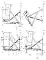
- Figs. 1-4 show a lifting truck which in a known way is provided with two forks 1 which can be lowered from the lifted position shown in the Figures to a lower position (not shown) where the forks are located immediately above a supporting surface 2.
- the forks may have a height of 90 mm above the floor while the forks in the lifted position shown may have a height of 800 mm above the support 2.
- the forks 1 are connected by means of a bracket 3 which also supports a hydraulic cylinder piston unit 4 which at the lower end is connected to a wheel frame 5 in which a wheel 6 is mounted upon which the lifting truck rests in its lowered position.
- the cylinder piston unit 4 is activated by means of a grip 7 which is also used as a control lever when driving the lifting truck.
- the forks 1 are secured in a chosen lifted position by means of a shear support comprising two pairs of shears (one of the pairs is shown in the Figure). At its one end the one shear 8 is hinged to the wheel frame 5 by a joint 9. At the other end 10 the shear 8 is provided with a roll (not shown) which supports the underside of the fork 1. The other shear 11 is hinged to the rearmost end of the fork 1 by a joint 12. At its frontmost lower end the shear 11 is provided with a travelling roller 13 and an extension extending beyond the travelling roller 13 and which forms a thrust pad 14 upon which the lifting truck rests when the shears occupy a predetermined steep position as shown in Fig. 1. In the embodiment shown the first shear is also connected with a thrust pad 15 which is located at an extension extending beyond the joint 9. In the position shown in Fig. 1 the lifting truck will be in a stable supporting position resting on the thrust pads 14,15.
- the forks 1 support goods 16 and a centre of gravity 17 for the goods 16 is at a distance 18 from the bracket 3 so that the total centre of gravity of the goods 16 as well as the lifting truck is located within the supporting area of the shear support.
- the distance 37 indicates the increase of the distance to an overturn point brought about by the thrust pad 14.
- a displacement of the centre of gravity 17 of the goods 16 occurs so that the goods are now at a distance 19 from the bracket 3.
- This displacement may cause the displacement of the total centre of gravity for the lifting truck and the goods 16 beyond the overturn point brought about by the thrust pad in the stable state illustrated in Fig. 1.
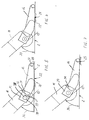
- Fig. 5 shows that in the position where a stable support is obtained as illustrated in Fig. 1, the thrust pad 14 rests on a first supporting surface 20 at the underside of the thrust pad 14.
- the thrust pad 14 comprises a second supporting surface 21 which is situated farther from the travelling roller 13 and extends upwards under an angle relative to the plane which includes the first supporting surface 20.
- the thrust pad 14 tilts around a line 22 that separates the first supporting surface and the second supporting surface 21.
- the thrust pad occupies a new stable state with the supporting surface 21 abutting the support 2.
- the third supporting surface 25 is situated under a small angle relative to the plane which includes the second supporting surface 21. In this situation even a quite small force 26 (See Fig. 3) applied to the grip of the lifting truck or a quite small further displacement of the centre of gravity on the lifting truck and the goods 16 will cause the forward tilting of the lifting truck to the position shown in Fig. 4.
- Fig. 4 shows an almost unimaginable situation where a user has ignored the forewarning given in the position shown in Fig. 2, and moreover, the unstable state of equilibrium which is illustrated in Fig. 3 has been exceeded.
- the lifting truck has tilted forwards and rests on the point of the forks 1 and on the outermost point of the thrust pad 14. For the sake of clearness no goods are shown in Fig. 4.
- the thrust pad 14 may be provided with a stay bolt 27 extending perpendicularly outwards from the side of the thrust pad 14 and the underside 28 being provided approximately in the plane which includes the third supporting surface 25.
- the thrust pad is pivotally embedded around its shaft 38 of the travelling roller 13.
- the embedding is provided by means of two flanges 29 (only one is shown) which pass on either side of the shear 11 and which is provided with a bore 30 through which the shaft 38 passes. Between the two flanges 29 a stopper 31 is shaped which co-operates with the terminal surface 32 of the shear 11 in order to reduce the rotating movement of the thrust pad 14.
- the stopper 31 Seen from the top side of the thrust pad the two flanges 29 form a U where the bottom of the U is constituted by the stopper 31.
- the stopper 31 may be made from sheets which are welded onto the inside of each flange 29, onto one of the flanges 29 or extend across the entire distance between the flanges 29 and thus constitute an end bottom in the U formed.
- the stopper 31 is made with two stop surfaces 33 extending obliquely inwards from the top side and the underside of the thrust pad 14 and in the direction where the pull of the travelling roller is provided. A swivelling embedding of the thrust pad 14 will trigger a double forewarning as described in the introductory part of the specification.
- the thrust pad is substantially banana-shaped having an edged profile at the underside.
- the angles between the edged profile formed by the supporting surfaces may be from approximately 1° to 5°.
- the angle 34, which the shear 11 forms with the support in the stable state may be 43°
- the angle 35, which the shear forms with the support in the stable forewarning position in Fig. 6, may then be within the range of 43-47°.
- the angle 36, which the shear 11 forms with the support 2 may be 48° in the unstable state of equilibrium shown in Fig. 3.
- the lifting height 23 and 24 for the position of the thrust pad 15 over the support will be 60 mm, respectively 100 mm. These lifting heights will give the user a clear indication of the imminent risk of tilting. With the stated data and if the goods 16 placed on the forks 1 weigh 500 kg, the force indicated in Fig. 3 will only have to be about 30 N to cause the complete tilting shown in Fig. 4.
Landscapes
- Engineering & Computer Science (AREA)
- Mechanical Engineering (AREA)
- Life Sciences & Earth Sciences (AREA)
- Geology (AREA)
- Structural Engineering (AREA)
- Chemical & Material Sciences (AREA)
- Combustion & Propulsion (AREA)
- Transportation (AREA)
- Forklifts And Lifting Vehicles (AREA)
- Handcart (AREA)
Claims (8)
- Hydraulischer Hubwagen mit einer Scherenstütze und umfassend zwei Gabeln (1), die an dem einen Ende mit einem eine an ihrem unteren Ende von einem Radgestell (5) unterstütze Hubkolbenzylindereinheit (4) enthaltenden Träger (3) verbunden sind, und zwei Paaren von Scherenarmen (8, 11), die zum Unterstützen von jeder der beiden Gabeln (1) gedacht sind, und bei dem der eine Scherenarm (8) an dem einen Ende gelenkig mit dem Radgestell (5) des Trägers verbunden ist und an dem anderen Ende (10) mit einer die Unterseite der Gabel (1) unterstützenden Walze versehen ist und bei dem der andere Scherenarm (11) an dem einen Ende gelenkig mit dem hinteren Ende der Gabel (1) verbunden ist und an dem anderen Ende mit einer Verfahrrolle (13) und einem sich über die Verfahrrolle (13) hinaus erstreckenden Fortsatz versehen ist zum Bilden eines Druckstückes (14), auf dem der Hubwagen ruht wenn die Scheren eine festgelegte, steile Stellung durch Anheben der Gabeln einnehmen, bei dem jedes der Druckstücke (14) an seiner Unterseite eine Unterstützungsfläche (20) aufweist, die als Normalunterstützungsfläche verwendet wird, wenn die Gabeln angehoben sind, gekennzeichnet durch eine weiter von der Verfahrrolle (13) entfernt angeordnete und sich bezüglich der Ebene, in der die erste Unterstützungsfläche (20) enthalten ist, unter einem spitzen Winkel nach oben erstreckende, zweite Unterstützungsfläche (21) und eine am weitesten von der Verfahrrolle (13) entfernt angeordnete und in Fortsetzung der ersten Unterstützungsfläche (20) und der zweiten Unterstützungsfläche (21) vorgesehene und sich bezüglich der Ebene, in der die zweite Unterstützungsfläche (21) enthalten ist unter einem spitzen Winkel nach oben erstreckende, dritte Unterstützungsfläche (25).
- Hubwagen nach Anspruch 1, dadurch gekennzeichnet, daß der Winkel zwischen der ersten Unterstützungsfläche (20) und der zweiten Unterstützungsfläche (21) im Bereich von etwa 1° bis näherungsweise 5° enthalten ist.
- Hubwagen nach Anspruch 1 oder 2, dadurch gekennzeichnet, daß der Winkel zwischen der zweiten Unterstützungsfläche (21) und der dritten Unterstützungsfläche (25) im Bereich von etwa 1° bis näherungsweise 5° enthalten ist.
- Hubwagen nach einem der vorhergehenden Ansprüche, dadurch gekennzeichnet, daß die dritte Unterstützungsfläche (25) des Druckstückes in der Längsrichtung des Scherenarms eine wesentliche kürzere Ausdehnung aufweist als die erste (20) und die zweite (21).
- Hubwagen nach einem der vorhergehenden Ansprüche, dadurch gekennzeichnet, daß lotrecht zur Orientierung der Druckstücke (14) in der Längsrichtung des Scherenarms in seitlicher Richtung vorspringende Ankerbolzen (27) sicher an den Seiten befestigt sind, wobei die Unterseiten (28) der Ankerbolzen näherungsweise in der Ebene angeordnet sind, in der die dritte Unterstützungsfläche (25) der Druckstücke enthalten ist.
- Hubwagen nach einem der vorhergehenden Ansprüche, dadurch gekennzeichnet, daß jedes Druckstück (14) schwenkbar um seine Verfahrrolle (13) eingebaut ist und daß die Drehbewegung des Druckstückes (14) mit Hilfe eines sicher auf dem Druckstück befestigten Stoppers (31) eingeschränkt ist, wobei der Stopper zum Angreifen an die Endfläche (32) des Scherenarms (11) gedacht ist.
- Hubwagen nach einem der vorhergehenden Ansprüche, dadurch gekennzeichnet, daß das Druckstück (14) aus einer von der Seite betrachtet im wesentlichen bananenformigen, langlichen Einheit hergestellt ist mit einem kantigen Profil an der Unterseite, an der die Unterstützungsflächen (20, 21, 25) gebildet sind, daß das Druckstück (14) an dem einen Ende der länglichen Einheit zwei vorspringende Flansche (29) aufweist, so daß von der Oberseite des Druckstückes (14) betrachtet eine im wesentlichen U-förmige Anordnung gebildet ist, und daß jeder der beiden Flansche (29) mit Bohrungen (30) versehen ist zur Schwenkverbindung des Druckstückes um seine Verfahrrolle (13).
- Hubwagen nach Anspruch 6 oder 7, dadurch gekennzeichnet, daß der Stopper (31) vom Endboden in dem zwischen den Flanschen (29) geschaffenen U gebildet ist, wobei der Boden mit zwei Flächen gebildet ist, die sich von der Oberseite und der Unterseite des Druckstückes (14) schräg nach innen und in Richtung auf die Verfahrrolle (13) erstrecken.
Applications Claiming Priority (2)
| Application Number | Priority Date | Filing Date | Title |
|---|---|---|---|
| DK1682/91 | 1991-10-01 | ||
| DK168291A DK167752B1 (da) | 1991-10-01 | 1991-10-01 | Hydraulisk gaffelloeftevogn med understoetning af saksetypen |
Publications (3)
| Publication Number | Publication Date |
|---|---|
| EP0520522A2 EP0520522A2 (de) | 1992-12-30 |
| EP0520522A3 EP0520522A3 (en) | 1993-02-03 |
| EP0520522B1 true EP0520522B1 (de) | 1994-05-18 |
Family
ID=8107167
Family Applications (1)
| Application Number | Title | Priority Date | Filing Date |
|---|---|---|---|
| EP19920114489 Expired - Lifetime EP0520522B1 (de) | 1991-10-01 | 1992-08-26 | Hydraulisch betätigter, auf Scheren gestützter Hebewagen |
Country Status (4)
| Country | Link |
|---|---|
| EP (1) | EP0520522B1 (de) |
| DE (1) | DE69200139T2 (de) |
| DK (1) | DK167752B1 (de) |
| ES (1) | ES2053346T3 (de) |
Families Citing this family (2)
| Publication number | Priority date | Publication date | Assignee | Title |
|---|---|---|---|---|
| CN109179256B (zh) * | 2018-11-09 | 2024-03-19 | 兰州工业学院 | 一种小型可移动式立体升降平台 |
| WO2024261746A1 (en) * | 2023-06-20 | 2024-12-26 | Ofer Levy | A system for loading and unloading of pallets to and from transport utilities using an autonomic forklift |
Family Cites Families (3)
| Publication number | Priority date | Publication date | Assignee | Title |
|---|---|---|---|---|
| US2300165A (en) * | 1942-04-13 | 1942-10-27 | Mustafa Ferhad | Hand truck |
| FR990485A (fr) * | 1948-07-09 | 1951-09-21 | H R G Engineering Company Ltd | Chariot pour le transport de plateaux à double fond |
| DE3642700C3 (de) * | 1986-11-25 | 1995-03-23 | Freimuth Gmbh | Hydraulischer Gabelhubwagen mit Scherenabstützung |
-
1991
- 1991-10-01 DK DK168291A patent/DK167752B1/da not_active IP Right Cessation
-
1992
- 1992-08-26 DE DE1992600139 patent/DE69200139T2/de not_active Expired - Fee Related
- 1992-08-26 EP EP19920114489 patent/EP0520522B1/de not_active Expired - Lifetime
- 1992-08-26 ES ES92114489T patent/ES2053346T3/es not_active Expired - Lifetime
Also Published As
| Publication number | Publication date |
|---|---|
| DE69200139T2 (de) | 1994-09-01 |
| DK168291A (da) | 1993-04-02 |
| EP0520522A3 (en) | 1993-02-03 |
| EP0520522A2 (de) | 1992-12-30 |
| DK168291D0 (da) | 1991-10-01 |
| DK167752B1 (da) | 1993-12-13 |
| ES2053346T3 (es) | 1994-07-16 |
| DE69200139D1 (de) | 1994-06-23 |
Similar Documents
| Publication | Publication Date | Title |
|---|---|---|
| US20050042068A1 (en) | Forklift with stabilizing forks | |
| US5489183A (en) | Hand truck for handling cylinders of compressed gas and the like | |
| EP0209502B1 (de) | Anordnung an Gabelstaplern | |
| US4065012A (en) | Low lift truck | |
| US5417541A (en) | Manual forklift pallet jack for unloading the contents of a beverage delivery truck | |
| US5911408A (en) | Transportable lift | |
| RU2131363C1 (ru) | Транспортное средство для подъема контейнера или аналогичного груза на погрузочную платформу и снятия их с нее | |
| US5222717A (en) | Booster arm for high-lift mechanism | |
| EP1045812B1 (de) | Hebevorrichtung mit einer hebbaren und kippbaren plattform | |
| JPH08511488A (ja) | 関節部付きブームを有する荷重処理自動車両 | |
| US5409346A (en) | Self-loading and unloading forklift truck | |
| US5217342A (en) | Self-loading and unloading forklift truck | |
| US6398480B1 (en) | Fork lift truck | |
| KR100517690B1 (ko) | 유압식 지게 카트 | |
| US6357990B1 (en) | Truck freight loading wheeled elevator | |
| EP0329946B1 (de) | Wagen | |
| EP0163407B1 (de) | Abschleppfahrzeug | |
| EP0520522B1 (de) | Hydraulisch betätigter, auf Scheren gestützter Hebewagen | |
| US4375903A (en) | Vehicle suspension system augmenter | |
| US4390314A (en) | Container truck for lifting and carrying away a container | |
| EP0726224A2 (de) | Fasshebe- und Transporteinrichtung | |
| US5346356A (en) | Fork-lift truck | |
| NL9400772A (nl) | Vorkhefwagen met vorksteun. | |
| US4101040A (en) | Vehicle for transporting palletized loads | |
| EP0961750A1 (de) | Bewegliche hebevorrichtung für güter |
Legal Events
| Date | Code | Title | Description |
|---|---|---|---|
| PUAI | Public reference made under article 153(3) epc to a published international application that has entered the european phase |
Free format text: ORIGINAL CODE: 0009012 |
|
| PUAL | Search report despatched |
Free format text: ORIGINAL CODE: 0009013 |
|
| ITCL | It: translation for ep claims filed |
Representative=s name: JACOBACCI CASETTA & PERANI S.P.A. |
|
| AK | Designated contracting states |
Kind code of ref document: A2 Designated state(s): CH DE ES FR GB IT LI NL SE |
|
| AK | Designated contracting states |
Kind code of ref document: A3 Designated state(s): CH DE ES FR GB IT LI NL SE |
|
| 17P | Request for examination filed |
Effective date: 19930624 |
|
| 17Q | First examination report despatched |
Effective date: 19930816 |
|
| GRAA | (expected) grant |
Free format text: ORIGINAL CODE: 0009210 |
|
| AK | Designated contracting states |
Kind code of ref document: B1 Designated state(s): CH DE ES FR GB IT LI NL SE |
|
| ITF | It: translation for a ep patent filed | ||
| REF | Corresponds to: |
Ref document number: 69200139 Country of ref document: DE Date of ref document: 19940623 |
|
| REG | Reference to a national code |
Ref country code: ES Ref legal event code: FG2A Ref document number: 2053346 Country of ref document: ES Kind code of ref document: T3 |
|
| ET | Fr: translation filed | ||
| EAL | Se: european patent in force in sweden |
Ref document number: 92114489.5 |
|
| PLBE | No opposition filed within time limit |
Free format text: ORIGINAL CODE: 0009261 |
|
| 26N | No opposition filed | ||
| PGFP | Annual fee paid to national office [announced via postgrant information from national office to epo] |
Ref country code: ES Payment date: 19960802 Year of fee payment: 5 |
|
| PGFP | Annual fee paid to national office [announced via postgrant information from national office to epo] |
Ref country code: NL Payment date: 19960828 Year of fee payment: 5 Ref country code: CH Payment date: 19960828 Year of fee payment: 5 |
|
| PG25 | Lapsed in a contracting state [announced via postgrant information from national office to epo] |
Ref country code: ES Free format text: LAPSE BECAUSE OF THE APPLICANT RENOUNCES Effective date: 19970827 |
|
| PG25 | Lapsed in a contracting state [announced via postgrant information from national office to epo] |
Ref country code: LI Free format text: LAPSE BECAUSE OF NON-PAYMENT OF DUE FEES Effective date: 19970831 Ref country code: CH Free format text: LAPSE BECAUSE OF NON-PAYMENT OF DUE FEES Effective date: 19970831 |
|
| PG25 | Lapsed in a contracting state [announced via postgrant information from national office to epo] |
Ref country code: NL Free format text: LAPSE BECAUSE OF NON-PAYMENT OF DUE FEES Effective date: 19980301 |
|
| REG | Reference to a national code |
Ref country code: CH Ref legal event code: PL |
|
| NLV4 | Nl: lapsed or anulled due to non-payment of the annual fee |
Effective date: 19980301 |
|
| REG | Reference to a national code |
Ref country code: ES Ref legal event code: FD2A Effective date: 20001102 |
|
| REG | Reference to a national code |
Ref country code: GB Ref legal event code: IF02 |
|
| PGFP | Annual fee paid to national office [announced via postgrant information from national office to epo] |
Ref country code: SE Payment date: 20020814 Year of fee payment: 11 |
|
| PG25 | Lapsed in a contracting state [announced via postgrant information from national office to epo] |
Ref country code: SE Free format text: LAPSE BECAUSE OF NON-PAYMENT OF DUE FEES Effective date: 20030827 |
|
| REG | Reference to a national code |
Ref country code: FR Ref legal event code: CD |
|
| EUG | Se: european patent has lapsed | ||
| PGFP | Annual fee paid to national office [announced via postgrant information from national office to epo] |
Ref country code: FR Payment date: 20040722 Year of fee payment: 13 |
|
| PGFP | Annual fee paid to national office [announced via postgrant information from national office to epo] |
Ref country code: DE Payment date: 20040726 Year of fee payment: 13 |
|
| PGFP | Annual fee paid to national office [announced via postgrant information from national office to epo] |
Ref country code: GB Payment date: 20040728 Year of fee payment: 13 |
|
| PG25 | Lapsed in a contracting state [announced via postgrant information from national office to epo] |
Ref country code: IT Free format text: LAPSE BECAUSE OF NON-PAYMENT OF DUE FEES;WARNING: LAPSES OF ITALIAN PATENTS WITH EFFECTIVE DATE BEFORE 2007 MAY HAVE OCCURRED AT ANY TIME BEFORE 2007. THE CORRECT EFFECTIVE DATE MAY BE DIFFERENT FROM THE ONE RECORDED. Effective date: 20050826 Ref country code: GB Free format text: LAPSE BECAUSE OF NON-PAYMENT OF DUE FEES Effective date: 20050826 |
|
| PG25 | Lapsed in a contracting state [announced via postgrant information from national office to epo] |
Ref country code: DE Free format text: LAPSE BECAUSE OF NON-PAYMENT OF DUE FEES Effective date: 20060301 |
|
| GBPC | Gb: european patent ceased through non-payment of renewal fee |
Effective date: 20050826 |
|
| PG25 | Lapsed in a contracting state [announced via postgrant information from national office to epo] |
Ref country code: FR Free format text: LAPSE BECAUSE OF NON-PAYMENT OF DUE FEES Effective date: 20060428 |
|
| REG | Reference to a national code |
Ref country code: FR Ref legal event code: ST Effective date: 20060428 |