EP0520304B1 - Analyser for the automatic analysis of body fluids - Google Patents
Analyser for the automatic analysis of body fluids Download PDFInfo
- Publication number
- EP0520304B1 EP0520304B1 EP92110182A EP92110182A EP0520304B1 EP 0520304 B1 EP0520304 B1 EP 0520304B1 EP 92110182 A EP92110182 A EP 92110182A EP 92110182 A EP92110182 A EP 92110182A EP 0520304 B1 EP0520304 B1 EP 0520304B1
- Authority
- EP
- European Patent Office
- Prior art keywords
- calibration
- reagent
- calibrator
- initiation
- parameter
- Prior art date
- Legal status (The legal status is an assumption and is not a legal conclusion. Google has not performed a legal analysis and makes no representation as to the accuracy of the status listed.)
- Expired - Lifetime
Links
- 238000004458 analytical method Methods 0.000 title claims abstract description 45
- 210000001124 body fluid Anatomy 0.000 title claims abstract description 4
- 239000010839 body fluid Substances 0.000 title claims abstract description 4
- 239000003153 chemical reaction reagent Substances 0.000 claims abstract description 94
- 230000000977 initiatory effect Effects 0.000 claims abstract description 31
- 238000006243 chemical reaction Methods 0.000 claims abstract description 20
- 239000007788 liquid Substances 0.000 claims abstract description 16
- 238000010521 absorption reaction Methods 0.000 claims description 16
- 238000005259 measurement Methods 0.000 claims description 9
- 239000012491 analyte Substances 0.000 claims description 7
- 230000003287 optical effect Effects 0.000 claims description 5
- 238000004519 manufacturing process Methods 0.000 claims description 2
- 238000012545 processing Methods 0.000 abstract description 7
- 239000000243 solution Substances 0.000 description 15
- 230000008859 change Effects 0.000 description 14
- 238000000034 method Methods 0.000 description 8
- 239000000126 substance Substances 0.000 description 7
- 238000012360 testing method Methods 0.000 description 7
- 238000001514 detection method Methods 0.000 description 5
- 238000011156 evaluation Methods 0.000 description 5
- 238000002156 mixing Methods 0.000 description 5
- 230000036962 time dependent Effects 0.000 description 5
- 238000005375 photometry Methods 0.000 description 4
- 230000008569 process Effects 0.000 description 4
- 210000002966 serum Anatomy 0.000 description 4
- 230000000737 periodic effect Effects 0.000 description 3
- 238000003860 storage Methods 0.000 description 3
- 210000002700 urine Anatomy 0.000 description 3
- BVKZGUZCCUSVTD-UHFFFAOYSA-M Bicarbonate Chemical compound OC([O-])=O BVKZGUZCCUSVTD-UHFFFAOYSA-M 0.000 description 2
- 230000006978 adaptation Effects 0.000 description 2
- 230000005540 biological transmission Effects 0.000 description 2
- 238000013461 design Methods 0.000 description 2
- 238000010586 diagram Methods 0.000 description 2
- 230000006870 function Effects 0.000 description 2
- 238000012544 monitoring process Methods 0.000 description 2
- 239000002904 solvent Substances 0.000 description 2
- 230000001960 triggered effect Effects 0.000 description 2
- 238000005406 washing Methods 0.000 description 2
- 230000008033 biological extinction Effects 0.000 description 1
- 238000011088 calibration curve Methods 0.000 description 1
- 238000002144 chemical decomposition reaction Methods 0.000 description 1
- 238000004140 cleaning Methods 0.000 description 1
- 238000001816 cooling Methods 0.000 description 1
- 230000001419 dependent effect Effects 0.000 description 1
- 238000005516 engineering process Methods 0.000 description 1
- 238000001704 evaporation Methods 0.000 description 1
- 230000008020 evaporation Effects 0.000 description 1
- 230000002349 favourable effect Effects 0.000 description 1
- 239000012530 fluid Substances 0.000 description 1
- 230000003993 interaction Effects 0.000 description 1
- 238000004806 packaging method and process Methods 0.000 description 1
- 238000012856 packing Methods 0.000 description 1
- 239000002504 physiological saline solution Substances 0.000 description 1
- 230000002028 premature Effects 0.000 description 1
- 238000009420 retrofitting Methods 0.000 description 1
- 238000004092 self-diagnosis Methods 0.000 description 1
- 238000003756 stirring Methods 0.000 description 1
- 238000012546 transfer Methods 0.000 description 1
Images


Classifications
-
- G—PHYSICS
- G01—MEASURING; TESTING
- G01N—INVESTIGATING OR ANALYSING MATERIALS BY DETERMINING THEIR CHEMICAL OR PHYSICAL PROPERTIES
- G01N35/00—Automatic analysis not limited to methods or materials provided for in any single one of groups G01N1/00 - G01N33/00; Handling materials therefor
- G01N35/00584—Control arrangements for automatic analysers
- G01N35/00594—Quality control, including calibration or testing of components of the analyser
- G01N35/00613—Quality control
- G01N35/00663—Quality control of consumables
-
- G—PHYSICS
- G01—MEASURING; TESTING
- G01N—INVESTIGATING OR ANALYSING MATERIALS BY DETERMINING THEIR CHEMICAL OR PHYSICAL PROPERTIES
- G01N35/00—Automatic analysis not limited to methods or materials provided for in any single one of groups G01N1/00 - G01N33/00; Handling materials therefor
- G01N35/00584—Control arrangements for automatic analysers
- G01N35/00594—Quality control, including calibration or testing of components of the analyser
- G01N35/00712—Automatic status testing, e.g. at start-up or periodic
-
- G—PHYSICS
- G01—MEASURING; TESTING
- G01N—INVESTIGATING OR ANALYSING MATERIALS BY DETERMINING THEIR CHEMICAL OR PHYSICAL PROPERTIES
- G01N35/00—Automatic analysis not limited to methods or materials provided for in any single one of groups G01N1/00 - G01N33/00; Handling materials therefor
- G01N35/02—Automatic analysis not limited to methods or materials provided for in any single one of groups G01N1/00 - G01N33/00; Handling materials therefor using a plurality of sample containers moved by a conveyor system past one or more treatment or analysis stations
- G01N35/025—Automatic analysis not limited to methods or materials provided for in any single one of groups G01N1/00 - G01N33/00; Handling materials therefor using a plurality of sample containers moved by a conveyor system past one or more treatment or analysis stations having a carousel or turntable for reaction cells or cuvettes
-
- G—PHYSICS
- G01—MEASURING; TESTING
- G01N—INVESTIGATING OR ANALYSING MATERIALS BY DETERMINING THEIR CHEMICAL OR PHYSICAL PROPERTIES
- G01N35/00—Automatic analysis not limited to methods or materials provided for in any single one of groups G01N1/00 - G01N33/00; Handling materials therefor
- G01N2035/00346—Heating or cooling arrangements
- G01N2035/00435—Refrigerated reagent storage
-
- G—PHYSICS
- G01—MEASURING; TESTING
- G01N—INVESTIGATING OR ANALYSING MATERIALS BY DETERMINING THEIR CHEMICAL OR PHYSICAL PROPERTIES
- G01N35/00—Automatic analysis not limited to methods or materials provided for in any single one of groups G01N1/00 - G01N33/00; Handling materials therefor
- G01N2035/00465—Separating and mixing arrangements
- G01N2035/00534—Mixing by a special element, e.g. stirrer
-
- G—PHYSICS
- G01—MEASURING; TESTING
- G01N—INVESTIGATING OR ANALYSING MATERIALS BY DETERMINING THEIR CHEMICAL OR PHYSICAL PROPERTIES
- G01N35/00—Automatic analysis not limited to methods or materials provided for in any single one of groups G01N1/00 - G01N33/00; Handling materials therefor
- G01N2035/00465—Separating and mixing arrangements
- G01N2035/00564—Handling or washing solid phase elements, e.g. beads
-
- G—PHYSICS
- G01—MEASURING; TESTING
- G01N—INVESTIGATING OR ANALYSING MATERIALS BY DETERMINING THEIR CHEMICAL OR PHYSICAL PROPERTIES
- G01N35/00—Automatic analysis not limited to methods or materials provided for in any single one of groups G01N1/00 - G01N33/00; Handling materials therefor
- G01N35/00584—Control arrangements for automatic analysers
- G01N35/00594—Quality control, including calibration or testing of components of the analyser
- G01N35/00613—Quality control
- G01N35/00663—Quality control of consumables
- G01N2035/00673—Quality control of consumables of reagents
-
- G—PHYSICS
- G01—MEASURING; TESTING
- G01N—INVESTIGATING OR ANALYSING MATERIALS BY DETERMINING THEIR CHEMICAL OR PHYSICAL PROPERTIES
- G01N35/00—Automatic analysis not limited to methods or materials provided for in any single one of groups G01N1/00 - G01N33/00; Handling materials therefor
- G01N35/02—Automatic analysis not limited to methods or materials provided for in any single one of groups G01N1/00 - G01N33/00; Handling materials therefor using a plurality of sample containers moved by a conveyor system past one or more treatment or analysis stations
- G01N35/04—Details of the conveyor system
- G01N2035/0439—Rotary sample carriers, i.e. carousels
- G01N2035/0441—Rotary sample carriers, i.e. carousels for samples
-
- G—PHYSICS
- G01—MEASURING; TESTING
- G01N—INVESTIGATING OR ANALYSING MATERIALS BY DETERMINING THEIR CHEMICAL OR PHYSICAL PROPERTIES
- G01N35/00—Automatic analysis not limited to methods or materials provided for in any single one of groups G01N1/00 - G01N33/00; Handling materials therefor
- G01N35/02—Automatic analysis not limited to methods or materials provided for in any single one of groups G01N1/00 - G01N33/00; Handling materials therefor using a plurality of sample containers moved by a conveyor system past one or more treatment or analysis stations
- G01N35/04—Details of the conveyor system
- G01N2035/0439—Rotary sample carriers, i.e. carousels
- G01N2035/0443—Rotary sample carriers, i.e. carousels for reagents
-
- G—PHYSICS
- G01—MEASURING; TESTING
- G01N—INVESTIGATING OR ANALYSING MATERIALS BY DETERMINING THEIR CHEMICAL OR PHYSICAL PROPERTIES
- G01N35/00—Automatic analysis not limited to methods or materials provided for in any single one of groups G01N1/00 - G01N33/00; Handling materials therefor
- G01N35/02—Automatic analysis not limited to methods or materials provided for in any single one of groups G01N1/00 - G01N33/00; Handling materials therefor using a plurality of sample containers moved by a conveyor system past one or more treatment or analysis stations
- G01N35/04—Details of the conveyor system
- G01N2035/0439—Rotary sample carriers, i.e. carousels
- G01N2035/0444—Rotary sample carriers, i.e. carousels for cuvettes or reaction vessels
-
- G—PHYSICS
- G01—MEASURING; TESTING
- G01N—INVESTIGATING OR ANALYSING MATERIALS BY DETERMINING THEIR CHEMICAL OR PHYSICAL PROPERTIES
- G01N35/00—Automatic analysis not limited to methods or materials provided for in any single one of groups G01N1/00 - G01N33/00; Handling materials therefor
- G01N35/10—Devices for transferring samples or any liquids to, in, or from, the analysis apparatus, e.g. suction devices, injection devices
- G01N35/1065—Multiple transfer devices
- G01N2035/1076—Multiple transfer devices plurality or independently movable heads
-
- G—PHYSICS
- G01—MEASURING; TESTING
- G01N—INVESTIGATING OR ANALYSING MATERIALS BY DETERMINING THEIR CHEMICAL OR PHYSICAL PROPERTIES
- G01N35/00—Automatic analysis not limited to methods or materials provided for in any single one of groups G01N1/00 - G01N33/00; Handling materials therefor
- G01N35/10—Devices for transferring samples or any liquids to, in, or from, the analysis apparatus, e.g. suction devices, injection devices
- G01N35/1081—Devices for transferring samples or any liquids to, in, or from, the analysis apparatus, e.g. suction devices, injection devices characterised by the means for relatively moving the transfer device and the containers in an horizontal plane
- G01N35/1083—Devices for transferring samples or any liquids to, in, or from, the analysis apparatus, e.g. suction devices, injection devices characterised by the means for relatively moving the transfer device and the containers in an horizontal plane with one horizontal degree of freedom
- G01N2035/1086—Cylindrical, e.g. variable angle
-
- Y—GENERAL TAGGING OF NEW TECHNOLOGICAL DEVELOPMENTS; GENERAL TAGGING OF CROSS-SECTIONAL TECHNOLOGIES SPANNING OVER SEVERAL SECTIONS OF THE IPC; TECHNICAL SUBJECTS COVERED BY FORMER USPC CROSS-REFERENCE ART COLLECTIONS [XRACs] AND DIGESTS
- Y10—TECHNICAL SUBJECTS COVERED BY FORMER USPC
- Y10T—TECHNICAL SUBJECTS COVERED BY FORMER US CLASSIFICATION
- Y10T436/00—Chemistry: analytical and immunological testing
- Y10T436/11—Automated chemical analysis
- Y10T436/115831—Condition or time responsive
Definitions
- the invention relates to an analysis system for the automatic analysis of body fluids.
- the system is used for the quantitative determination of several different analytes (parameters).
- Components of the system are an analysis device, reaction vessels that are transported on the device to various processing stations, liquid reagents that are kept in the device in test tubes and the contents of which are sufficient for a large number of analyzes, and at least one liquid calibrator that contains at least one analyte contains in a known concentration.
- the system can also include other components, such as special sample vessels or control solutions.
- the analysis systems to which the invention relates are often used as wet chemical selective multi-parameter analyzers designated. On them, individual reaction vessels are transported past different processing stations, often using a rotor that can be rotated in stages.
- the processing stations include pipetting stations to add the samples and reagents in a defined quantity to the reaction vessels, often a mixing device for mixing and finally a measuring device to determine a physically detectable measurement variable on the reaction solution contained in the reaction vessels after the analysis reaction has ended.
- the optical absorption is usually measured in transmission.
- the wet chemical analyzers differ from the likewise widespread analysis systems, in which an analysis element is used for each individual analysis, which contains the reagents required for the individual analysis in a packing unit (usually in dry form).
- the packaging unit can have very different shapes, for example as test strips, so-called analysis chips, or as a "test pack".
- analysis systems are hereinafter referred to collectively as test pack analysis systems.
- the wet chemical analyzers are characterized above all by low analysis costs because the reagents do not have to be packed individually in the smallest units. On the other hand, it is much more difficult than with test pack systems to meet the constantly increasing requirements for simple operation, security against operating errors and little time required for the operating personnel.
- the present invention is particularly directed to the calibration of automatic wet chemical analyzers. Due to instabilities of both the reagents and the device, it is necessary to calibrate the system from time to time with the help of a calibrator, i.e. a liquid that contains the respective analyte (parameter) in a known concentration.
- a calibrator i.e. a liquid that contains the respective analyte (parameter) in a known concentration.
- This defines an evaluation curve (functional relationship between the physical measured variable, e.g. absorption, and the concentration sought) and stores it in the device. Since the evaluation curve for tests based on a photometric transmission measurement usually has a straight course, a calibration on a single calibrator with a concentration other than zero is usually sufficient for the calibration in addition to the measurement of a blank value. Under certain circumstances (in the case of a non-linear course of the calibration curve), several calibrations in different concentration ranges of a parameter are required.
- the Japanese patent application with the publication number 62-144071 describes the possibility, in addition to the conventionally carried out calibration, to measure the extinction of a zero standard (blank) at certain periodic intervals in order to take account of time-dependent changes in the reagent.
- An important example of a parameter in which such a periodic readjustment of the zero value is advantageous is the analysis of bicarbonate, which is based on the detection of CO 2 . It is characteristic of this test that the properties of the reagent change relatively quickly due to the inevitable absorption of CO 2 from the air. It is therefore necessary to adjust the zero value of the calibration at regular intervals. This is done by measuring a physiological saline solution as a blank. In contrast to conventional calibrators with a concentration not equal to zero, this is easily stable in storage.
- this method is only an adaptation of the evaluation curve originally defined (using a calibrator with a concentration not equal to zero) in a conventional manner to the time-dependent change of the reagent, the evaluation curve in each case in adaptation to the measured zero value is moved.
- the method is not readily transferable to other parameters. In practice, it is used exclusively to adjust the zero value when determining bicarbonate.
- the rigid periodic execution of the adjustment measurement at constant intervals is not suitable for a fully automatic calibration.
- a system according to claim 1 is proposed according to the invention.
- the calibrator is ready for use in liquid form in a calibrator station of the analyzer (ie in such a way that it can be removed from the calibrator vessel and analyzed without human intervention).
- the calibration for various parameters can be initiated (initiated) and carried out independently of one another automatically (ie without an operator having to intervene).
- the calibration initiation cycle at least one system-inherent calibration influencing variable is queried, logically linked with a control value specifically defined for the respective parameter, and the decision about the initiation of the calibration is made automatically, taking into account the result of the logical link.
- the calibration initiation cycle is expediently carried out in succession for all analysis parameters for which the device is set up. This process is repeated continuously or at certain intervals.
- the invention allows the necessary calibrations to be carried out without human intervention. This prevents errors.
- the initiation of the calibration is specifically tailored to the parameter and system-inherent calibration influencing variables are also taken into account in the context of the calibration initiation cycle. In many cases, this enables longer intervals between calibrations of a certain parameter, thereby saving. Time and cost achieved.
- disruptive factors that require premature recalibration can be recognized automatically.
- Significant progress is being made with regard to the long-desired goal of analysis technology that wet chemical analysis systems should work independently of the operator (stand-alone operation ").
- the invention overcomes the prevailing view in the specialist world that analytical reliability requires that calibration steps be initiated individually and carried out with a freshly prepared calibrator.
- the initiation of a calibration is based on a defined algorithm called the calibration initiation cycle. As will be explained in more detail below, this algorithm is specifically matched to the parameter. This refers to the selection of one or more system-related influencing variables that are taken into account when initiating the calibration of a specific parameter. It relates further on the definition of the respective defined control value and the type of logical link.
- System-inherent calibration influencing variables in the sense of the invention are states or properties of components of the analysis system including the samples which are important for the need to initiate a calibration.
- quantities could be found (which have no direct relation to the type of calibrator, its setpoint value or its actual measured concentration value (actual value)), by monitoring them the need for calibration during the operation of a diagnostic analysis system is automatically recognized so that the initiation of the calibration is possible at the right time.
- These influencing variables which are inherent in the system, are suitable for characterizing the state of the overall system, consisting of samples, calibrators, control solutions, reagents and analysis device, to the extent necessary for initiating the calibration. Through their monitoring, the cause that makes a calibration necessary for a parameter (or is suitable for postponing a calibration) can be recognized automatically. The system is therefore capable of self-diagnosis and - since the calibration is carried out automatically - also of self-regulation.
- a system-inherent calibration influencing variable can be a measured value (for example the absorption or the pH value of a reagent).
- the control value with which the detected measured value is linked is a numerical value.
- it can also be information communicated to the system in machine-readable form trade about a system component (for example, the reagent lot and the bottle number of the reagent).
- sample serum or urine
- the type of sample is taken into account by logically linking it with stored information as to whether a calibration for this type of sample and the parameters requested in connection therewith already exist.
- control value can be both a logical value denoting a state and a numerical value. In general, it is a value that is used to control the calibration initiation cycle by logically combining it with an inherent influencing variable suitable is. If the influencing variable inherent in the system is a continuously variable variable, such as the absorption value of the reagent, the control value is usually a threshold value or a range of values for these variables.
- the control value normally also has only two logical states (eg logical 0 for "no calibration") when changing bottles "and logical 1 for” calibration when changing bottles ").
- control solution can basically be the same calibrator with which the calibration was carried out.
- a special control solution is used, which is kept ready for use in a control solution station of the device. As a result, such calibration errors are also recognized which have their cause in the calibrator.
- the calibrator station and possibly the control solution station are cooled. This reduces errors due to evaporation and / or chemical decomposition of the calibrator or the control solution.
- the cooling does require considerable technical effort, but this is more than compensated for by the advantages of the invention.
- the calibrator In order to ensure calibration automatically during an entire day of operation, the calibrator should be "stable in the day” in liquid state and in contact with air, i.e. the concentration of the analyte in question should remain in the setpoint range for a full working day.
- the analysis system 1 shown in FIG. 1 has a reaction rotor 3, two reagent rotors 4 and 5 with reagent vessels 9 and a sample rotor 6 with sample vessels 7 on a processing table 2.
- Numerous reaction vessels 8 are arranged in a circle on the reaction rotor 3.
- the swivel arms 10a to 14a of the various stations are computer-controlled and serve to sample and to transfer the reagents into the reaction vessels 8 at the right time, or to immerse a stirring paddle of the mixing stations 13, 14 in the reaction vessels 8 for mixing.
- the photometric measurement takes place through the reagent vessels, which are designed as optical cuvettes in the lower part.
- the photometry station is therefore located under the cover of the processing table 2 and is symbolized by an arrow 16.
- a special feature of the system according to the invention is the calibrator station 17, which is integrated in the sample rotor 6 in the case shown. It contains several calibrators which are kept ready for use in liquid form in calibrator vessels 18. The number of calibrators required depends on the number of parameters and on the possibility of using multi-parameter calibrators, in which several different analytes are contained in known concentration in a single solution. In order to ensure the desired daily stability, it is often advantageous to use single calibrators within the scope of the invention. Since handling is automatic, there is practically no additional effort involved.
- the calibrator station 17 contains additional control vessels 19 which contain control solutions. Overall, the calibrator station 17 should be cooled (for example with the help of Peltier elements). The openings of the calibrator vessels 18 and the control vessels 19 are within the reach of the pipetting needle which can be pivoted on the arm 12a of the sample pipetting station 12 and can thus be transferred into a reaction vessel 8 on the reaction rotor 3 instead of a sample.
- Both the liquid calibrators kept in stock in the calibrator vessels 18 and the control solutions kept in stock in the control vessels 19 contain the respective analytes in known concentrations.
- a calibrator and a control solution for a particular parameter may be the same.
- solutions are used as calibrators in which the concentration of the respective analyte is in a very narrow setpoint range and the analyte is dissolved in a solvent which ensures a high stability of the calibrator.
- serum or a serum-like liquid is preferably used as the solvent and the target value range of the analyte is somewhat wider.
- the rotor 6 is rotated to a position in which the required calibrator is located in the swivel range of the arm 12a of the sample pipetting station 12, without human intervention being required.
- a measured portion of the calibrator is removed from the calibrator vessel 18 and transferred to the reaction vessel 8.
- reagents are added in the usual way and the color change resulting from the reaction is determined photometrically.
- This measured value is defined in the computer of the device as a new calibration factor and used in the same way as for manually initiated calibrations to correct the evaluation curve.
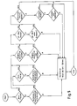
- FIG. 2 illustrates the interaction of the various components (shown in the form of a block diagram) of a system according to the invention.
- a microprocessor-controlled central unit 20 with memory 25 serves in the usual way to control a rotor controller 21 and a treatment station controller 22 in order to perform the required rotary movements of the rotors 3, 4, 5 and 6, movement, suction, exhaust, washing and To control measuring operations of the treatment stations 10 to 16.
- the measured values of the photometry station 16 are supplied to the central unit 20 via a measured value acquisition 23, processed and output via a data output 24 to data output units, not shown, such as a printer or a screen.
- a total of 26 means are provided for taking into account various influencing variables inherent in the system, the value of which influences the initiation of a calibration. Shown are a reagent vessel detector 27, a reagent fill level detector 28, a reagent absorption detector 29, a reagent pH detector 30 and the memory 25.
- the individual detectors can be largely conventional.
- the term "detection” is understood broadly to mean any form of detection or observation of an influencing variable inherent in the system.
- FIG. 3 shows a preferred form of a reagent vessel detector 27.
- the reagent vessel 9 bears a machine-readable coding in the form of a bar code 33 on a label (label) 32.
- a reflection code reader 34 is provided on the device side, which is of conventional design and is only shown symbolically in the figure .
- the reflection code reader 34 is installed on the periphery of the respective reagent rotor 4, 5 in such a way that it can read the bar code on the reagent vessels 9 located in the device.
- a reagent vessel detector 27 constructed in this way fulfills a double function within the scope of the invention. On the one hand, it serves to recognize the change of a reagent tube. Secondly, it allows barcode 33 to be read. This contains information about the batch of the reagent and preferably also about the identity of the reagent bottle (production number). In addition to initiating a calibration, reading this barcode can also be used for additional security measures. In particular, it is checked whether the correct reagent is used (reagent identification). In addition, it can be determined whether the same bottle is used multiple times in the device, which suggests misuse of the reagent vessel which impairs the accuracy of the analysis.
- the calibrator vessels also preferably carry a label 36 with a bar code 37.
- a bar code reader 38 which is again of conventional design, is used to record the coded information.
- the code 37 contains in particular information about the parameter or parameters of the calibrator. This ensures "positive calibrator identification", i.e. a mix-up of the calibrator is excluded.
- the detection of the reagent liquid level (fill level) in the reagent vessels 9 can be carried out according to known methods, for example with the aid of a conductivity measurement or with the aid of a capacitance measurement.
- the measuring device is preferably located on the suction needle of the respective pipetting arm 10a, 11a, so that the height position of the respective pipette is detected when immersed in the reagent liquid.
- Such a level detector is already present in many devices in order to generate a warning signal when the reagent supply in one of the vessels 9 is running low.
- a conventional pH electrode is preferably used as the reagent pH detector, which can be arranged on the reaction rotor 3 or also directly on the reagent rotor 4 or 5.
- a pH detector is arranged under the table 2, the filling openings 30a and 30b of which are each positioned in the pivoting range of the arms 10a, 11a of the reagent pipetting stations 10, 11, so that a sample of the reagent can be placed in the respective filling opening 30a if necessary , 30b can be transferred.
- the photometry station 16 serves as the reagent absorption detector, the pure reagent being photometrized without the addition of a sample.
- the memory 25 of the central unit 20 is also to be regarded as a means of taking into account influencing variables inherent in the system if such variables are stored there. In particular, this can be information about the samples or analyzes, as will be explained in more detail below.
- system feedback of the system-inherent influencing variables in the form of a logical connection influences the initiation of a calibration. Examples are explained with reference to FIG. 5.
- the flowchart of a calibration initiation cycle for a parameter is shown, in which, in addition to a calibration interval, the change of the reagent vessel, the change of the batch of the reagent, the fill level of the reagent, the pH value and the reagent absorption are taken into account as influencing factors inherent in the system.
- the cycle shown runs automatically on the device at defined intervals. Similar cycles are carried out individually for the individual parameters.
- a query is made as to whether a new calibration is required when changing the bottle.
- the answer depends on the respective reagent and thus on the parameter. It is saved as a logical control value for each parameter when the system is set up. In the case of reagents with critical stability properties, the answer "yes" is saved and a calibration is carried out each time the reagent bottle is changed.
- the query is made as to whether the reagent absorption is relevant for the respective parameter. This was also saved for each parameter when the system was set up. If the answer is "yes”, a query is made as to whether the reagent absorption is above a (parameter-specific, stored as control value) limit value. If the result is positive, calibration is carried out.
- the counter is reset, which controls the course of the calibration interval.
- system-inherent influencing variables are made using logical links taken into account, on the one hand, to trigger additional calibration processes (when changing bottles or batches or when the pH or absorption limit values are reached) and, on the other hand, to avoid unnecessary calibration processes (when the reagent is low).
- the calibration takes place at defined time intervals each time a calibration interval has elapsed.
- Influencing factors that are directly linked to the state of the reagent can also be used to initiate a calibration process, completely independently of the time lapse.
- Such influencing variables are the absorption of the reagent or its pH. It has been found that these quantities may be a better indicator of the condition of the reagent than the passage of time.
- Changes to reagents in wet chemical analyzers are dependent on a number of influencing factors, for example the temperature, the air humidity, the age of the reagents before opening the reagent container (ie the storage time) and the like.
- "worst case” considerations must be taken into account when determining a calibration interval that is only defined in terms of time, ie the calibration interval that ensures timely calibration under the most unfavorable conditions is selected. If instead an indicator that is characteristic of the condition of the reagent is determined, the calibration can be carried out less frequently under favorable circumstances without the analysis accuracy suffering.
- information about the sample or the analyzes which are stored in the memory 25 can also be taken into account as influencing variables inherent in the system when initiating a calibration.
- the system is used to analyze several different types of samples (e.g. serum and urine), information about the sample sequence can be stored and queried. This makes it possible to recalibrate in good time before analyzing the first sample of another type of sample.
- samples e.g. serum and urine
- Information about the analyzes stored in the memory 25 can also be important for initiating a calibration. For example, before each calibration, an additional query can be made as to whether the respective parameter was requested as an analysis value for the samples to be processed in the near future. If this is not the case, the calibration can be postponed accordingly. If such a device is present, on the other hand, it should be possible to detect specially defined samples, in particular so-called "emergency samples", for which purpose either a sample detector with a bar code reader (similar to FIGS. 3 and 4) or information stored in the memory 25 can be used . This ensures that when additional emergency samples are inserted into the previously planned sample sequence, a new calibration is carried out if a parameter has to be determined whose calibration was initially postponed.
- Service interventions in the analysis system or retrofitting of the system can also be taken into account as influencing factors inherent in the system. If the analysis system registers such interventions itself and stores the relevant information, an automatic recalibration can be triggered.
- calibration is initiated on a parameter-specific basis, i.e. individually adapted to the requirements of the respective parameter. It may be expedient to initiate the calibration in a time-dependent manner for some parameters and to take other influencing variables into account only in addition, while for other parameters the calibration is initiated on the basis of one or more indicators characteristic of the condition of the reagent.
- a comparator circuit is the suitable standard hardware for implementing such a step of the calibration initiation cycle.
- the decisions during the calibration initiation cycle are preferably software-controlled by appropriate programming of a microprocessor, which is part of the central unit 20 of the analysis device.
Landscapes
- Chemical & Material Sciences (AREA)
- Analytical Chemistry (AREA)
- General Health & Medical Sciences (AREA)
- Health & Medical Sciences (AREA)
- Life Sciences & Earth Sciences (AREA)
- Quality & Reliability (AREA)
- Engineering & Computer Science (AREA)
- Biochemistry (AREA)
- Physics & Mathematics (AREA)
- General Physics & Mathematics (AREA)
- Immunology (AREA)
- Pathology (AREA)
- Chemical Kinetics & Catalysis (AREA)
- Automatic Analysis And Handling Materials Therefor (AREA)
- Investigating Or Analyzing Non-Biological Materials By The Use Of Chemical Means (AREA)
Abstract
Description
Die Erfindung betrifft ein Analysesystem zur automatischen Analyse von Körperflüssigkeiten. Das System dient zur quantitativen Bestimmung von mehreren unterschiedlichen Analyten (Parametern). Bestandteile des Systems sind ein Analysegerät, Reaktionsgefäße, die auf dem Gerät zu verschiedenen Bearbeitungsstationen transportiert werden, flüssige Reagenzien, die in dem Gerät in Reagenzgefäßen bereitgehalten werden und deren Inhalt für eine Vielzahl von Analysen ausreicht, sowie mindestens ein flüssiger Kalibrator, der mindestens einen Analyten in einer bekannten Konzentration enthält. Darüber hinaus kann das System weitere Bestandteile, wie beispielsweise spezielle Probengefäße oder Kontrollösungen einschließen.The invention relates to an analysis system for the automatic analysis of body fluids. The system is used for the quantitative determination of several different analytes (parameters). Components of the system are an analysis device, reaction vessels that are transported on the device to various processing stations, liquid reagents that are kept in the device in test tubes and the contents of which are sufficient for a large number of analyzes, and at least one liquid calibrator that contains at least one analyte contains in a known concentration. The system can also include other components, such as special sample vessels or control solutions.
Die Analysesysteme, auf die sich die Erfindung bezieht, werden vielfach als naßchemische selektive Mehrparameter-Analyseautomaten bezeichnet. Auf ihnen werden einzelne Reaktionsgefäße an verschiedenen Bearbeitungsstationen vorbeitransportiert, wobei als Transportmittel häufig ein stufenweise drehbarer Rotor dient. Zu den Bearbeitungsstationen gehören Pipettierstationen, um die Proben und Reagenzien in definierter Menge in die Reaktionsgefäße zu geben, häufig eine Mischeinrichtung zur Vermischung und schließlich eine Meßeinrichtung, um nach Ablauf der Analysereaktion eine physikalisch nachweisbare Meßgröße an der in den Reaktionsgefäßen enthaltenen Reaktionslösung zu bestimmen. Meist wird die optische Absorption in Transmission gemessen.The analysis systems to which the invention relates are often used as wet chemical selective multi-parameter analyzers designated. On them, individual reaction vessels are transported past different processing stations, often using a rotor that can be rotated in stages. The processing stations include pipetting stations to add the samples and reagents in a defined quantity to the reaction vessels, often a mixing device for mixing and finally a measuring device to determine a physically detectable measurement variable on the reaction solution contained in the reaction vessels after the analysis reaction has ended. The optical absorption is usually measured in transmission.
In diesen konstruktiven Elementen unterscheiden sich die naßchemischen Analyseautomaten von den ebenfalls weit verbreiteten Analysesystemen, bei denen für jede einzelne Analyse ein Analyseelement verwendet wird, das die jeweils für die einzelne Analyse erforderlichen Reagenzien in einer Packungseinheit (meist in trockener Form) enthält. Die Packungseinheit kann ganz verschiedene Formen, beispielsweise als Teststreifen, sogenannte Analysechips, oder als "Testpack" haben. Solche Analysesysteme werden nachfolgend insgesamt als Testpack-Analysesysteme bezeichnet.In these constructive elements, the wet chemical analyzers differ from the likewise widespread analysis systems, in which an analysis element is used for each individual analysis, which contains the reagents required for the individual analysis in a packing unit (usually in dry form). The packaging unit can have very different shapes, for example as test strips, so-called analysis chips, or as a "test pack". Such analysis systems are hereinafter referred to collectively as test pack analysis systems.
Die naßchemischen Analyseautomaten zeichnen sich vor allem durch geringe Analysekosten aus, weil die Reagenzien nicht jeweils einzeln in kleinsten Einheiten verpackt werden müssen. Andererseits ist es sehr viel schwieriger als bei Testpack-Systemen, die ständig steigenden Anforderungen an eine einfache Bedienung, Sicherheit gegen Bedienungsfehler und geringen Zeitbedarf hinsichtlich des Bedienungspersonals zu realisieren.The wet chemical analyzers are characterized above all by low analysis costs because the reagents do not have to be packed individually in the smallest units. On the other hand, it is much more difficult than with test pack systems to meet the constantly increasing requirements for simple operation, security against operating errors and little time required for the operating personnel.
Die vorliegende Erfindung richtet sich speziell auf die Kalibration von naßchemischen Analyseautomaten. Aufgrund von Instabilitäten sowohl der Reagenzien, als auch des Gerätes ist es erforderlich, das System von Zeit zu Zeit mit Hilfe eines Kalibrators, also einer Flüssigkeit, die den jeweiligen Analyten (Parameter) in bekannter Konzentration enthält, zu Kalibrieren. Damit wird eine Auswertekurve (funktionaler Zusammenhang zwischen der physikalischen Meßgröße, z.B. Absorption, und der gesuchten Konzentration) festgelegt und im Gerät abgespeichert. Da die Auswertekurve bei Tests, die auf einer photometrischen Transmissionsmessung beruhen, meist einen geraden Verlauf hat, genügt für die Kalibration in der Regel neben der Messung eines Leerwertes ("Blank") eine Messung an einem einzigen Kalibrator mit einer Konzentration ungleich Null. Unter Umständen sind (bei einem nichtlinearen Verlauf der Kalibrationskurve) auch mehrere Kalibrationen in verschiedenen Konzentrationsbereichen eines Parameters erforderlich.The present invention is particularly directed to the calibration of automatic wet chemical analyzers. Due to instabilities of both the reagents and the device, it is necessary to calibrate the system from time to time with the help of a calibrator, i.e. a liquid that contains the respective analyte (parameter) in a known concentration. This defines an evaluation curve (functional relationship between the physical measured variable, e.g. absorption, and the concentration sought) and stores it in the device. Since the evaluation curve for tests based on a photometric transmission measurement usually has a straight course, a calibration on a single calibrator with a concentration other than zero is usually sufficient for the calibration in addition to the measurement of a blank value. Under certain circumstances (in the case of a non-linear course of the calibration curve), several calibrations in different concentration ranges of a parameter are required.
Dabei sind vor allem folgende Kalibrationsverfahren üblich:
- a) Der Kalibrator wird von einer Bedienungsperson in das System eingebracht und die Kalibration wird für den gewünschten Parameter durch manuelle Eingabe angefordert. Dabei bestimmt das Bedienungspersonal den Zeitpunkt jeder Kalibration anhand von Vorschriften der Reagenz- bzw. Gerätehersteller.
- b) In dem Analysegerät sind zeitliche Intervalle (Kalibrationsintervalle) gespeichert. Jeweils nach Ablauf eines solchen Intervalls wird das Bedienungspersonal aufgefordert, eine Kalibration manuell einzuleiten. Eine Variante dieses Systems, bei der für jeden Parameter ein gesondertes Kalibrationsintervall abgespeichert wird, ist in der US-Patentschrift 4 678 755 beschrieben. Dabei wird die Notwendigkeit einer Kalibration für den Benutzer in verschiedenerlei Weise (beispielsweise als Tabelle auf einem Bildschirm) angezeigt und es kann zusätzlich ein akustischer Alarm ausgelöst werden, um auf das Erfordernis der Kalibration hinzuweisen.
- a) The calibrator is introduced into the system by an operator and the calibration is requested for the desired parameter by manual input. The operator determines the time of each calibration based on the instructions of the reagent or device manufacturer.
- b) Time intervals (calibration intervals) are stored in the analyzer. After such an interval has expired, the operating personnel are asked to initiate a calibration manually. A variant of this system in which a separate calibration interval is saved for each parameter is described in U.S. Patent 4,678,755. The need for a calibration for the user is displayed in various ways (for example as a table on a screen) and an acoustic alarm can also be triggered to indicate the need for the calibration.
In der japanischen Patentanmeldung mit der Publikationsnummer 62-144071 ist die Möglichkeit beschrieben, in Ergänzung zu der konventionell durchgeführten Kalibration in bestimmten periodischen Abständen die Extinktion eines Null-Standards (Blank) nachzumessen, um dadurch zeitabhängige Veränderungen des Reagenz zu berücksichtigen. Ein wichtiges Beispiel eines Parameters, bei dem eine solche periodische Nachstellung des Null-Wertes vorteilhaft ist, ist die Analyse von Bicarbonat, die auf der Detektion von CO2 basiert. Charakteristisch für diesen Test ist, daß die Eigenschaften des Reagenz sich durch die unvermeidliche Aufnahme von CO2 aus der Luft verhältnismäßig schnell ändern. Es ist deshalb erforderlich, den Null-Wert der Kalibration in regelmäßigen Zeitabständen nachzustellen. Dies geschieht durch eine Messung an einer physiologischen Kochsalzlösung als Blank. Diese ist, im Gegensatz zu üblichen Kalibratoren mit einer Konzentration ungleich Null, problemlos lagerbeständig.The Japanese patent application with the publication number 62-144071 describes the possibility, in addition to the conventionally carried out calibration, to measure the extinction of a zero standard (blank) at certain periodic intervals in order to take account of time-dependent changes in the reagent. An important example of a parameter in which such a periodic readjustment of the zero value is advantageous is the analysis of bicarbonate, which is based on the detection of CO 2 . It is characteristic of this test that the properties of the reagent change relatively quickly due to the inevitable absorption of CO 2 from the air. It is therefore necessary to adjust the zero value of the calibration at regular intervals. This is done by measuring a physiological saline solution as a blank. In contrast to conventional calibrators with a concentration not equal to zero, this is easily stable in storage.
Obwohl in der genannten Druckschrift von einer Kalibration gesprochen wird, handelt es sich bei diesem Verfahren nur um eine Anpassung der ursprünglich (unter Verwendung eines Kalibrators mit einer Konzentration ungleich Null) in konventioneller Weise festgelegten Auswertekurve an die zeitabhängige Änderung des Reagenz, wobei die Auswertekurve jeweils in Anpassung an den gemessenen Null-Wert verschoben wird. Das Verfahren ist auf andere Parameter nicht ohne weiteres übertragbar. In der Praxis wird es ausschließlich zur Anpassung des Null-Wertes bei der Bicarbonatbestimmung eingesetzt. Die starre periodische Durchführung der Anpassungsmessung in konstanten Abständen ist für eine vollautomatische Kalibration nicht geeignet.Although the document mentioned speaks of a calibration, this method is only an adaptation of the evaluation curve originally defined (using a calibrator with a concentration not equal to zero) in a conventional manner to the time-dependent change of the reagent, the evaluation curve in each case in adaptation to the measured zero value is moved. The method is not readily transferable to other parameters. In practice, it is used exclusively to adjust the zero value when determining bicarbonate. The rigid periodic execution of the adjustment measurement at constant intervals is not suitable for a fully automatic calibration.
Um einen hohen Grad an Analysegenauigkeit mit reduzierter Wahrscheinlichkeit von Bedienungsfehlern und ohne wesentliche Erhöhung der System-Gesamtkosten zu erreichen, wird erfindungsgemäß ein System gemäß Anspruch 1 vorgeschlagen. Der Kalibrator ist in einer Kalibratorstation des Analysegerätes in flüssiger Form gebrauchsfertig (d.h. so, daß er ohne menschliches Zutun aus dem Kalibratorgefäß entnommen und analysiert werden kann) vorrätig. Die Kalibration für verschiedene Parameter kann unabhängig voneinander automatisch (d.h. ohne daß eine Bedienungsperson eingreifen muß) eingeleitet (initiiert) und durchgeführt werden. In den Kalibrationsinitiierungszyklus wird jeweils mindestens eine systemimmanente Kalibrations-Einflußgröße abgefragt, mit einem für den jeweiligen Parameter spezifisch definierten Steuerungswert logisch verknüpft und die Entscheidung über die Initiierung der Kalibration unter Berücksichtigung des Ergebnisses der logischen Verknüpfung automatisch getroffen. Zweckmäßigerweise wird der Kalibrationsinitiierungszyklus nacheinander für sämtliche Analyseparameter, für die das Gerät eingerichtet ist, durchgeführt. Dieser Prozeß wird fortlaufend oder in bestimmten Zeitabständen wiederholt.In order to achieve a high degree of analysis accuracy with a reduced probability of operating errors and without a significant increase in the total system costs, a system according to claim 1 is proposed according to the invention. The calibrator is ready for use in liquid form in a calibrator station of the analyzer (ie in such a way that it can be removed from the calibrator vessel and analyzed without human intervention). The calibration for various parameters can be initiated (initiated) and carried out independently of one another automatically (ie without an operator having to intervene). In the calibration initiation cycle, at least one system-inherent calibration influencing variable is queried, logically linked with a control value specifically defined for the respective parameter, and the decision about the initiation of the calibration is made automatically, taking into account the result of the logical link. The calibration initiation cycle is expediently carried out in succession for all analysis parameters for which the device is set up. This process is repeated continuously or at certain intervals.
Die Erfindung erlaubt die Durchführung der erforderlichen Kalibrationen ohne menschliche Eingriffe. Dadurch werden Fehler vermieden. Die Initiierung der Kalibration ist jeweils spezifisch auf den Parameter abgestimmt und es werden zusätzlich systemimmanente Kalibrations-Einflußgrößen im Rahmen des Kalibrationsinitiierungszyklus berücksichtigt. Dadurch werden einerseits in vielen Fällen längere zeitliche Abstände der Kalibrationen eines bestimmten Parameters ermöglicht und damit eine Einsparung an. Zeit und Kosten erzielt. Andererseits können Störfaktoren, die eine vorzeitige Neukalibration erforderlich machen, automatisch erkannt werden. Es wird ein wesentlicher Fortschritt im Hinblick auf das in der Analysetechnik seit langem angestrebte Ziel erreicht, daß naßchemische Analysesysteme Operator-unabhängig arbeiten sollen (stand-alone-Betrieb").The invention allows the necessary calibrations to be carried out without human intervention. This prevents errors. The initiation of the calibration is specifically tailored to the parameter and system-inherent calibration influencing variables are also taken into account in the context of the calibration initiation cycle. In many cases, this enables longer intervals between calibrations of a certain parameter, thereby saving. Time and cost achieved. On the other hand, disruptive factors that require premature recalibration can be recognized automatically. Significant progress is being made with regard to the long-desired goal of analysis technology that wet chemical analysis systems should work independently of the operator (stand-alone operation ").
Die Erfindung überwindet die in der Fachwelt vorherrschenden Auffassung, daß die Analysesicherheit es erfordere, Kalibrationsschritte jeweils individuell einzuleiten und mit einem frisch zubereiteten Kalibrator durchzuführen.The invention overcomes the prevailing view in the specialist world that analytical reliability requires that calibration steps be initiated individually and carried out with a freshly prepared calibrator.
Die Initiierung einer Kalibration läuft auf Basis eines definierten Algorithmus ab, der als Kalibrationsinitiierungszyklus bezeichnet wird. Dieser Algorithmus ist, wie im folgenden noch näher erläutert wird, jeweils spezifisch auf den Parameter abgestimmt. Dies bezieht sich auf die Auswahl von einer oder mehreren systemimmanenten Einflußgrößen, die bei der Initiierung der Kalibration eines bestimmten Parameters berücksichtigt werden. Es bezieht sich weiter auf die Festlegung des jeweiligen definierten Steuerungswertes und die Art der logischen Verknüpfung.The initiation of a calibration is based on a defined algorithm called the calibration initiation cycle. As will be explained in more detail below, this algorithm is specifically matched to the parameter. This refers to the selection of one or more system-related influencing variables that are taken into account when initiating the calibration of a specific parameter. It relates further on the definition of the respective defined control value and the type of logical link.
Systemimmanente Kalibrations-Einflußgrößen (die man auch als Kalibrationsindikatoren bezeichnen kann) im Sinne der Erfindung sind Zustände oder Eigenschaften von Bestandteilen des Analysesystems einschließlich der Proben, die für die Notwendigkeit, eine Kalibration zu initiieren, von Bedeutung sind. Im Rahmen der Erfindung konnten Größen gefunden werden (die keinen unmittelbaren Bezug zur Art des Kalibrators, dessen Konzentrations-Sollwert oder dessen tatsächlichem Konzentrations-Meßwert (Ist-Wert) haben), durch deren Überwachung die Notwendigkeit für eine Kalibration während des Betriebes eines diagnostischen Analysesystems automatisch erkannt wird, so daß die Initiierung der Kalibration zum richtigen Zeitpunkt möglich ist. Diese systemimmanenten Einflußgrößen sind geeignet, den Zustand des Gesamtsystems, bestehend aus Proben, Kalibratoren, Kontrollösungen, Reagenzien und Analysegerät in dem jeweils für die Initiierung der Kalibration erforderlichen Umfang zu charakterisieren. Durch ihre Überwachung kann die Ursache, die eine Kalibration für einen Parameter erforderlich macht (bzw. geeignet ist, eine Kalibration hinauszuschieben) automatisch erkannt werden. Das System ist somit zur Selbstdiagnose und - da die Kalibration automatisch durchgeführt wird - auch zur Selbstregelung fähig.System-inherent calibration influencing variables (which can also be called calibration indicators) in the sense of the invention are states or properties of components of the analysis system including the samples which are important for the need to initiate a calibration. Within the scope of the invention, quantities could be found (which have no direct relation to the type of calibrator, its setpoint value or its actual measured concentration value (actual value)), by monitoring them the need for calibration during the operation of a diagnostic analysis system is automatically recognized so that the initiation of the calibration is possible at the right time. These influencing variables, which are inherent in the system, are suitable for characterizing the state of the overall system, consisting of samples, calibrators, control solutions, reagents and analysis device, to the extent necessary for initiating the calibration. Through their monitoring, the cause that makes a calibration necessary for a parameter (or is suitable for postponing a calibration) can be recognized automatically. The system is therefore capable of self-diagnosis and - since the calibration is carried out automatically - also of self-regulation.
Eine systemimmanente Kalibrations-Einflußgröße kann ein Meßwert (beispielsweise die Absorption oder der pH-Wert eines Reagenz) sein. In diesem Fall ist der Steuerungswert, mit dem der detektierte Meßwert verknüpft wird, ein Zahlenwert. Es kann sich jedoch auch um eine in maschinenlesbarer Form dem System mitgeteilte Information über einen Systembestandteil (beispielsweise die Reagenzcharge und die Flaschennummer des Reagenz) handeln.A system-inherent calibration influencing variable can be a measured value (for example the absorption or the pH value of a reagent). In this case, the control value with which the detected measured value is linked is a numerical value. However, it can also be information communicated to the system in machine-readable form trade about a system component (for example, the reagent lot and the bottle number of the reagent).
Schließlich sind als systemimmanente Kalibrations-Einflußgrößen auch Informationen anzusehen, die in einem Analysegerät üblicherweise ohnehin vorliegen, im Rahmen der Erfindung jedoch in neuartiger Weise zur automatischen Initiierung einer Kalibration verwendet werden. Beispiele hierfür sind die Art der Proben (insbesondere Serum oder Urin), für welche innerhalb eines automatischen Analyselaufes (Run) des Gerätes Analysen durchgeführt werden sollen, sowie die für die einzelnen Proben angeforderten Analysen (Parameter) und die daraus üblicherweise vom Computer des Gerätes berechnete Sequenz, mit der die Anforderungen abgearbeitet werden. In diesem Falle kann als Steuerungswert beispielsweise einen Grenz-Zahlenwert von Analysen eingegeben sein, die für einen bestimmten Parameter am Ende eines Run noch durchgeführt werden können, ohne daß eine Kalibration erforderlich ist. Die Probenart (Serum oder Urin) wird durch logische Verknüpfung mit einer abgespeicherten Information berücksichtigt, ob eine Kalibration für diese Probenart und den in Verbindung hiermit angeforderten Parameter bereits vorliegt. Diese verschiedenen Möglichkeiten der Berücksichtigung systemimmanenter Einflußgrößen werden im folgenden noch näher erläutert.Finally, information that is inherent in the system and that is normally present in an analysis device, but is used in a novel manner for the automatic initiation of a calibration is also to be regarded as a system-inherent calibration influencing variable. Examples of this are the type of samples (in particular serum or urine) for which analyzes are to be carried out within an automatic analysis run (run) of the device, as well as the analyzes (parameters) requested for the individual samples and the ones usually calculated from them by the computer of the device Sequence with which the requests are processed. In this case, a limit numerical value of analyzes can be entered as the control value, for example, which can still be carried out for a specific parameter at the end of a run, without the need for calibration. The type of sample (serum or urine) is taken into account by logically linking it with stored information as to whether a calibration for this type of sample and the parameters requested in connection therewith already exist. These various options for taking system-influencing factors into account are explained in more detail below.
Es wird deutlich, daß der Steuerungswert sowohl ein einen Zustand bezeichnender logischer Wert, als auch ein Zahlenwert sein kann. Allgemein ist es ein Wert, der zur Steuerung des Kalibrationsinitiierungszyklus durch logische Verknüpfung mit einer systemimmanenten Einflußgröße geeignet ist. Wenn die systemimmanente Einflußgröße eine kontinuierlich veränderliche Variable, wie beispielsweise der Absorptionswert des Reagenz ist, ist der Steuerungswert in der Regel ein Schwellwert oder ein Wertebereich dieser Variablen. Wenn die Kalibrations-Einflußgröße lediglich zwei logische Zustände hat, wie beispielsweise bei der Abfrage eines Reagenzflaschenwechsels (keine neue Flasche entspricht logisch 0, neue Flasche entspricht logisch 1), hat der Steuerungswert normalerweise ebenfalls nur zwei logische Zustände (z.B. logisch 0 für "keine Kalibration bei Flaschenwechsel" und logisch 1 für "Kalibration bei Flaschenwechsel").It is clear that the control value can be both a logical value denoting a state and a numerical value. In general, it is a value that is used to control the calibration initiation cycle by logically combining it with an inherent influencing variable suitable is. If the influencing variable inherent in the system is a continuously variable variable, such as the absorption value of the reagent, the control value is usually a threshold value or a range of values for these variables. If the calibration influencing variable has only two logical states, such as when querying for a reagent bottle change (no new bottle corresponds to logical 0, new bottle corresponds to logical 1), the control value normally also has only two logical states (eg logical 0 for "no calibration") when changing bottles "and logical 1 for" calibration when changing bottles ").
Da die Notwendigkeit einer neuen Kalibration eines bestimmten Parameters wesentlich von zeitabhängigen Veränderungen der verwendeten Reagenzien abhängt, erfolgt auch die Initiierung einer Kalibration meist in erster Linie zeitabhängig, wobei für jeden Parameter ein Kalibrationsintervall abgespeichert ist. Erfindungsgemäß erfolgt jedoch zusätzlich ein "System-feedback", bei dem weitere Einflußgrößen durch logische Verknüpfung berücksichtigt werden.Since the need for a new calibration of a certain parameter depends essentially on time-dependent changes in the reagents used, the initiation of a calibration is usually primarily time-dependent, with a calibration interval being stored for each parameter. According to the invention, however, there is also a "system feedback" in which further influencing variables are taken into account by means of a logical link.
Eine weitere Erhöhung der Zuverlässigkeit und Analysesicherheit wird durch folgende bevorzugte Maßnahmen erreicht.A further increase in reliability and analytical reliability is achieved by the following preferred measures.
Nach jeder Kalibration eines Parameters sollte eine Kontrollmessung mit einer Kontrollösung bekannter Konzentration des gleichen Parameters durchgeführt werden. Dadurch werden Fehler bei der Kalibrations-Messung, beispielsweise durch eine Luftblase im Photometer, erkannt. Die Kontrollösung kann grundsätzlich der gleiche Kalibrator sein, mit dem die Kalibration durchgeführt wurde. Vorzugsweise wird jedoch eine spezielle Kontrollösung verwendet, die in einer Kontrollösung-Station des Gerätes gebrauchsfertig vorrätig gehalten wird. Dadurch werden auch solche Kalibrationsfehler erkannt, die ihre Ursache in dem Kalibrator haben.After each calibration of a parameter, a control measurement should be carried out with a control solution of known concentration of the same parameter. As a result, errors in the calibration measurement, for example due to an air bubble in the photometer, are recognized. The control solution can basically be the same calibrator with which the calibration was carried out. Preferably However, a special control solution is used, which is kept ready for use in a control solution station of the device. As a result, such calibration errors are also recognized which have their cause in the calibrator.
Die Kalibratorstation und gegebenenfalls die Kontrollösungsstation (welche vorteilhaft räumlich zusammengefaßt sind) sind gekühlt. Hierdurch werden Fehler durch Verdunstung und/oder chemische Zersetzung des Kalibrators bzw. der Kontrollösung reduziert. Die Kühlung erfordert zwar einen erheblichen technischen Aufwand, jedoch wird dieser durch die Vorteile der Erfindung mehr als ausgeglichen.The calibrator station and possibly the control solution station (which are advantageously spatially combined) are cooled. This reduces errors due to evaporation and / or chemical decomposition of the calibrator or the control solution. The cooling does require considerable technical effort, but this is more than compensated for by the advantages of the invention.
Um die Kalibration während eines ganzen Betriebstages automatisch zu gewährleisten, sollte der Kalibrator in flüssigem Zustand und in Kontakt mit Luft "tagesstabil" sein, d.h. die Konzentration des jeweiligen Analyten sollte während eines vollen Arbeitstages im Sollwertbereich bleiben.In order to ensure calibration automatically during an entire day of operation, the calibrator should be "stable in the day" in liquid state and in contact with air, i.e. the concentration of the analyte in question should remain in the setpoint range for a full working day.
Die Erfindung wird im folgenden anhand eines in den Figuren schematisch dargestellten Ausführungsbeispiels näher erläutert; es zeigen:
- Fig. 1
- Eine Aufsicht auf ein für die Erfindung geeignetes Analysegerät,
- Fig. 2
- ein Blockschaltbild eines für die Erfindung geeigneten Analysegerätes,
- Fig. 3
- eine perspektivische Prinzipdarstellung eines Reagenzgefäßdetektors,
- Fig. 4
- eine perspektivische Prinzipdarstellung eines Kalibratorgefäßdetektors,
- Fig. 5
- ein Ablaufdiagramm zur Verdeutlichung des funktionalen Ablaufs in einem erfindungsgemäßen Analysesystem.
- Fig. 1
- A supervision of an analysis device suitable for the invention,
- Fig. 2
- 2 shows a block diagram of an analysis device suitable for the invention,
- Fig. 3
- 1 shows a perspective illustration of a reagent vessel detector,
- Fig. 4
- 1 shows a perspective illustration of a calibrator vessel detector,
- Fig. 5
- a flowchart to illustrate the functional flow in an analysis system according to the invention.
Das in Figur 1 dargestellte Analysesystem 1 weist auf einem Bearbeitungstisch 2 einen Reaktionsrotor 3, zwei Reagenzrotoren 4 und 5 mit Reagenzgefäßen 9 und einen Probenrotor 6 mit Probengefäßen 7 auf. Auf dem Reaktionsrotor 3 sind kreisförmig zahlreiche Reaktionsgefäße 8 angeordnet. An der Peripherie des Reaktionsrotors 3 befinden sich verschiedene Bearbeitungsstationen, nämlich Pipettierstationen 10, 11, 12, Mischstationen 13,14 und eine Waschstation 15 zum Reinigen der Reaktionsgefäße 8. Die Schwenkarme 10a bis 14a der verschiedenen Stationen werden computergesteuert und dienen dazu, die Probe und die Reagenzien jeweils zum richtigen Zeitpunkt in die Reaktionsgefäße 8 zu transferieren, bzw. ein Rührpaddel der Mischstationen 13,14 zum Mischen in die Reaktionsgefäße 8 einzutauchen. Die photometrische Messung erfolgt bei dem dargestellten Gerät durch die Reagenzgefäße hindurch, die im unteren Teil als optische Küvetten ausgebildet sind. Die Photometriestation befindet sich deshalb unter der Abdeckung des Bearbeitungstisches 2 und ist durch einen Pfeil 16 symbolisiert.The analysis system 1 shown in FIG. 1 has a reaction rotor 3, two reagent rotors 4 and 5 with
Insoweit ist der Aufbau des Systems konventionell und muß nicht näher erläutert werden.In this respect, the structure of the system is conventional and need not be explained in more detail.
Eine Besonderheit des erfindungsgemäßen Systems ist die Kalibratorstation 17, die im dargestellten Fall in den Probenrotor 6 integriert ist. Sie enthält mehrere Kalibratoren, die in flüssiger Form in Kalibratorgefäßen 18 gebrauchsfertig vorrätig gehalten werden. Die Zahl der erforderlichen Kalibratoren hängt von der Anzahl der Parameter und von der Möglichkeit ab, Mehr-Parameter-Kalibratoren zu verwenden, bei denen mehrere verschiedene Analyten in bekannter Konzentration in einer einzigen Lösung enthalten sind. Um die gewünschte Tagesstabilität zu gewährleisten, ist es im Rahmen der Erfindung häufig vorteilhaft Einfach-Kalibratoren einzusetzen. Da die Handhabung automatisch geschieht, ist hiermit praktisch kein zusätzlicher Aufwand verbunden.A special feature of the system according to the invention is the
Die Kalibratorstation 17 enthält im dargestellten bevorzugten Fall zusätzliche Kontrollgefäße 19, die Kontrollösungen enthalten. Insgesamt sollte die Kalibratorstation 17 (beispielsweise mit Hilfe von Peltier-Elementen) gekühlt sein. Die Öffnungen der Kalibratorgefäße 18 und der Kontrollgefäße 19 befinden sich in der Reichweite der an dem Arm 12a der Proben-Pipettierstation 12 schwenkbaren Pipettiernadel und können somit statt einer Probe in ein Reaktionsgefäß 8 auf dem Reaktionsrotor 3 transferiert werden.In the preferred case shown, the
Sowohl die in den Kalibratorgefäßen 18 vorrätig gehaltenen flüssigen Kalibratoren als auch die in den Kontrollgefäßen 19 vorrätig gehaltenen Kontrollösungen enthalten die jeweiligen Analyten in bekannten Konzentrationen. Ein Kalibrator und eine Kontrollösung für einen bestimmten Parameter können unter Umständen identisch sein. Vielfach werden jedoch als Kalibratoren Lösungen eingesetzt, bei denen die Konzentration des jeweiligen Analyten in einem sehr engen Sollwertbereich liegt und der Analyt in einem Lösungsmittel gelöst ist, das eine hohe Stabilität des Kalibrators gewährleistet. Bei einer Kontrollösung wird dagegen vorzugsweise Serum oder eine serumartige Flüssigkeit als Lösungsmittel verwendet und der Sollwertbereich des Analyten ist etwas breiter.Both the liquid calibrators kept in stock in the
Zur Durchführung einer Kalibration wird - ohne daß ein menschliches Eingreifen erforderlich ist - der Rotor 6 jeweils in eine Position gedreht, in der sich der benötigte Kalibrator im Schwenkbereich des Arms 12a der Probenpipettierstation 12 befindet. Eine abgemessene Teilmenge des Kalibrators wird aus dem Kalibratorgefäß 18 entnommen und in das Reaktionsgefäß 8 transferiert. Dort werden in üblicher Weise Reagenzien zugegeben und die aus der Reaktion resultierende Farbänderung wird photometrisch bestimmt. Dieser Meßwert wird im Computer des Gerätes als neuer Kalibrationsfaktor definiert und in gleicher Weise wie bei manuell initiierten Kalibrationen zur Korrektur der Auswertekurve verwendet.In order to carry out a calibration, the
Figur 2 verdeutlicht das Zusammenwirken der verschiedenen (in Form eines Blockschaltbilds dargestellten) Komponenten eines erfindungsgemäßen Systems. Eine mikroprozessorgesteuerte Zentraleinheit 20 mit Speicher 25 dient in üblicher Weise dazu, eine Rotorsteuerung 21 und eine Behandlungsstation-Steuerung 22 anzusteuern, um die erforderlichen Drehbewegungen der Rotoren 3, 4, 5 und 6, Bewegungs-, Ansaug-, Ausstoß-, Wasch- und Meßvorgänge der Behandlungsstationen 10 bis 16 zu steuern. Die Meßwerte der Photometriestation 16 werden über eine Meßwerterfassung 23 an die Zentraleinheit 20 geliefert, verarbeitet und über einen Datenausgang 24 an nicht dargestellte Datenausgabeeinheiten, wie beispielsweise einen Drucker oder einen Bildschirm, ausgegeben.Figure 2 illustrates the interaction of the various components (shown in the form of a block diagram) of a system according to the invention. A microprocessor-controlled
Wesentlich für die Erfindung ist, daß insgesamt mit 26 bezeichnete Mittel zur Berücksichtigung verschiedener systemimmanenter Einflußgrößen vorhanden sind, deren Wert die Initiierung einer Kalibration beeinflußt. Dargestellt sind ein Reagenzgefäßdetektor 27, ein ReagenzfüllstandsDetektor 28, ein Reagenzabsorptionsdetektor 29, ein Reagenz-pH-Detektor 30 sowie der Speicher 25.It is essential for the invention that a total of 26 means are provided for taking into account various influencing variables inherent in the system, the value of which influences the initiation of a calibration. Shown are a
Die einzelnen Detektoren können weitgehend konventionell ausgebildet sein. Der Begriff "Detektion" wird dabei breit verstanden als jede Form der Erfassung oder Beobachtung einer systemimmanenten Einflußgröße.The individual detectors can be largely conventional. The term "detection" is understood broadly to mean any form of detection or observation of an influencing variable inherent in the system.
Figur 3 zeigt eine bevorzugte Form eines Reagenzgefäßdetektors 27. Das Reagenzgefäß 9 trägt auf einem Etikett (Label) 32 eine maschinenlesbare Codierung in Form eines Barcode 33. Geräteseitig ist ein Reflexions-Codeleser 34 vorgesehen, der konventionell aufgebaut und in der Figur lediglich symbolisch dargestellt ist.FIG. 3 shows a preferred form of a
Der Reflexions-Codeleser 34 ist an der Pheripherie des jeweiligen Reagenzrotors 4,5 so eingebaut, daß er den Barcode auf den im Gerät befindlichen Reagenzgefäßen 9 lesen kann. Ein so aufgebauter Reagenzgefäßdetektor 27 erfüllt im Rahmen der Erfindung eine doppelte Funktion. Zum einen dient er dazu, den Wechsel eines Reagenzgefäßes zu erkennen. Zum zweiten erlaubt er, den Barcode 33 zu lesen. Dieser enthält eine Information über die Charge des Reagenz und vorzugsweise zusätzlich über die Identität der Reagenzflasche (Herstellungs-Nummer). Das Lesen dieses Barcodes kann zusätzlich zu der Initiierung einer Kalibration auch zu ergänzenden Sicherheitsmaßnahmen genutzt werden. Insbesondere wird kontrolliert, ob das richtige Reagenz eingesetzt ist (Reagenzidentifikation). Außerdem kann festgestellt werden, ob die gleiche Flasche mehrfach in das Gerät eingesetzt wird, was auf einen die Analysegenauigkeit beeinträchtigenden Mißbrauch des Reagenzgefäßes schließen läßt.The
Wie in Figur 4 dargestellt ist, tragen auch die Kalibratorgefäße bevorzugt ein Etikett 36 mit einem Barcode 37. Ein wiederum konventionell ausgebildeter Barcodeleser 38 dient zur Erfassung der codierten Information. Der Code 37 enthält insbesondere Informationen über den bzw. die Parameter des Kalibrators. Dadurch wird eine "positive Kalibratoridentifikation" gewährleistet, d.h. eine Verwechslung des Kalibrators wird ausgeschlossen.As shown in FIG. 4, the calibrator vessels also preferably carry a
Die Detektion des Reagenz-Flüssigkeitsstandes (Füllstandes) in den Reagenzgefäßen 9 kann nach bekannten Verfahren zum Beispiel mit Hilfe einer Leitfähigkeitsmessung oder mit Hilfe einer Kapazitätsmessung erfolgen. Die Meßeinrichtung befindet sich bevorzugt an der Absaugnadel des jeweiligen Pipettierarmes 10a, 11a, so daß die Höhenposition des jeweiligen Pipettors beim Eintauchen in die Reagenzflüssigkeit detektiert wird. Ein solcher Füllstandsdetektor ist bei vielen Geräten ohnehin vorhanden, um ein Warnsignal zu erzeugen, wenn der Reagenzvorrat in einem der Gefäße 9 zur Neige geht.The detection of the reagent liquid level (fill level) in the
Als Reagenz-pH-Detektor wird vorzugsweise eine übliche pH-Elektrode verwendet, die an dem Reaktionsrotor 3 oder auch unmittelbar an dem Reagenzrotor 4 bzw. 5 angeordnet sein kann. Im dargestellten Fall ist ein pH-Detektor unter dem Tisch 2 angeordnet, dessen Einfüllöffnungen 30a und 30b jeweils im Schwenkbereich der Arme 10a,11a der Reagenz-Pipettierstationen 10,11 positioniert sind, so daß bei Bedarf eine Probe des Reagenz in die jeweilige Einfüllöffnung 30a,30b transferiert werden kann.A conventional pH electrode is preferably used as the reagent pH detector, which can be arranged on the reaction rotor 3 or also directly on the reagent rotor 4 or 5. In the illustrated case, a pH detector is arranged under the table 2, the filling
Für die Detektion der optischen Absorption des Reagenz sind keine zusätzlichen konstruktiven Mittel erforderlich. Als Reagenzabsorptionsdetektor dient vielmehr die Photometriestation 16, wobei das reine Reagenz ohne Zugabe von Probe photometriert wird.No additional constructive means are required for the detection of the optical absorption of the reagent. Rather, the
Auch der Speicher 25 der Zentraleinheit 20 ist als Mittel zur Berücksichtigung systemimmanenter Einflußgrößen anzusehen, wenn solche Größen dort gespeichert werden. Insbesondere kann es sich dabei um Informationen über die Proben oder Analysen handeln, wie weiter unten näher erläutert wird.The
Wie erwähnt, hat der Systemfeedback der systemimmanenten Einflußgrößen in Form einer logischen Verknüpfung Einfluß auf die Initiierung einer Kalibration. Beispiele werden anhand von Figur 5 erläutert.As mentioned, the system feedback of the system-inherent influencing variables in the form of a logical connection influences the initiation of a calibration. Examples are explained with reference to FIG. 5.
Dargestellt ist das Ablaufdiagramm eines Kalibrationsinitiierungszyklus für einen Parameter, bei dem neben einem Kalibrationsintervall der Wechsel des Reagenzgefäßes, der Wechsel der Charge des Reagenz, der Füllstand des Reagenz, der pH-Wert und die Reagenzabsorption als systemimmanente Einflußgrößen berücksichtigt werden. Der dargestellt Zyklus läuft auf dem Gerät in festgelegten Zeitabständen automatisch ab. Gleichartige Zyklen werden nacheinander für die einzelnen Parameter individuell durchgeführt.The flowchart of a calibration initiation cycle for a parameter is shown, in which, in addition to a calibration interval, the change of the reagent vessel, the change of the batch of the reagent, the fill level of the reagent, the pH value and the reagent absorption are taken into account as influencing factors inherent in the system. The cycle shown runs automatically on the device at defined intervals. Similar cycles are carried out individually for the individual parameters.
Innerhalb des Zyklus erfolgt zunächst eine Abfrage, ob (seit dem letzten Kalibrationsinitiierungszyklus des gleichen Parameters) ein Wechsel des Reagenzgefäßes (Flasche) durchgeführt wurde. Dies wird durch den Reagenzgefäßdetektor angezeigt, wobei der Flaschenwechsel zu einer Zustandsänderung eines Speicherelementes (Flip-Flop) führt, dessen Ist-Wert in dieser Stufe des Zyklus abgefragt wird.Within the cycle, there is first a query as to whether (since the last calibration initiation cycle of the same parameter) a change of the reagent vessel (bottle) was carried out. This is indicated by the reagent vessel detector, the bottle change leading to a change in state of a storage element (flip-flop) whose actual value is queried at this stage of the cycle.
Falls ein Flaschenwechsel vorgenommen wurde, erfolgt eine Abfrage, ob bei Flaschenwechsel eine Neukalibration erforderlich ist. Die Antwort ist abhängig vom jeweiligen Reagenz und damit von dem Parameter. Sie wird bei der Einrichtung des Systems für jeden Parameter als logischer Steuerungswert abgespeichert. Bei Reagenzien mit kritischen stabilitätseigenschaften wird die Antwort "ja" gespeichert und es erfolgt eine Kalibration bei jedem Wechsel der Reagenzflasche.If a bottle change has been made, a query is made as to whether a new calibration is required when changing the bottle. The answer depends on the respective reagent and thus on the parameter. It is saved as a logical control value for each parameter when the system is set up. In the case of reagents with critical stability properties, the answer "yes" is saved and a calibration is carried out each time the reagent bottle is changed.
Falls die zuletzt erwähnte Abfrage zu der Antwort "nein" führt, erfolgen entsprechende Abfragen hinsichtlich des Wechsels der Charge bzw. der Erforderlichkeit einer Neukalibration bei Chargenwechsel. Dadurch wird berücksichtigt, daß beim Wechsel eines Reagenzgefäßes häufig eine neue Charge des Reagenz verwendet wird und dieser Chargenwechsel auch in solchen Fällen eine Neukalibration erfordern kann, in denen der Flaschenwechsel bei gleichbleibender Charge nicht zur Initiierung einer Kalibration führt.If the last-mentioned query leads to the answer "no", corresponding queries regarding the change of the batch or the necessity of a recalibration when changing the batch are carried out. This takes into account the fact that when changing a reagent tube, a new batch of reagent is often used and this batch change can also require a new calibration in those cases in which changing the bottle with the same batch does not lead to the initiation of a calibration.
Falls eine dieser Abfragen oder die erste Abfrage (hinsichtlich des Flaschenwechsels) zur Antwort "nein" führt, erfolgt die Abfrage, ob die Reagenzabsorption für den jeweiligen Parameter relevant ist. Auch dies ist bei der Einrichtung des Systems für jeden Parameter abgespeichert worden. Ist die Antwort "ja", so erfolgt eine Abfrage, ob die Reagenzabsorption über einem (parameterspezifischen, als Steuerungswert abgespeicherten) Grenzwert liegt. Bei positivem Ergebnis erfolgt eine Kalibration.If one of these queries or the first query (regarding the bottle change) leads to the answer "no", the query is made as to whether the reagent absorption is relevant for the respective parameter. This was also saved for each parameter when the system was set up. If the answer is "yes", a query is made as to whether the reagent absorption is above a (parameter-specific, stored as control value) limit value. If the result is positive, calibration is carried out.
Ist die Antwort auf eine der Abfragen hinsichtlich der Reagenzabsorption "nein", erfolgen entsprechende Abfragen hinsichtlich des pH-Wertes. In diesem Fall erfolgt eine Kalibration, wenn der pH-Wert unter einem als Steuerungswert abgespeicherten Grenzwert liegt.If the answer to one of the queries regarding reagent absorption is "no", corresponding queries regarding the pH value are made. In this case, calibration takes place when the pH value is below a limit value stored as a control value.
Wenn auch hier beide Abfragen mit "nein" beantwortet werden, erfolgt als nächstes die Abfrage, ob das Kalibrationsintervall abgelaufen ist. Bei der Antwort "nein" ist der Zyklus beendet.If both queries are answered with "no", the next question is whether the calibration interval has expired. If the answer is "no", the cycle is ended.
Bei der Antwort "ja" erfolgen zwei weitere Anfragen zum Füllstand des Reagenz in dem jeweiligen Reagenzgefäß. Zweck dieser Abfragen ist es, den mit der Neukalibration verbundenen Aufwand an Kalibratorflüssigkeit und Maschinenzeit zu vermeiden, wenn der Füllstand unterhalb eines definierten Grenzwertes ist (d.h. nur noch eine geringe Restmenge Reagenz in dem Reagenzbehälter vorhanden ist) und für den fraglichen Parameter eine geringfügige Überschreitung des Kalibrationsintervalls toleriert werden kann. Falls entweder der Füllstand für den betreffenden Parameter nicht relevant ist (d.h. auch bei niedrigem Füllstand eine Kalibration erfolgen soll) oder der Füllstand über dem als Steuerungswert abgespeicherter Grenzwert liegt, wird eine Kalibration initiiert. Dagegen entfällt sie, wenn der Füllstand relevant ist und unterhalb des Grenzwertes liegt.If the answer is "yes", two further questions about the fill level of the reagent are made in the respective reagent vessel. The purpose of these queries is to avoid the expenditure of calibrator fluid and machine time associated with the recalibration if the level is below a defined limit value (ie only a small amount of reagent is left in the reagent container) and the parameter in question is slightly exceeded Calibration interval can be tolerated. If either the level is not relevant for the relevant parameter (i.e. a calibration should also be carried out at a low level) or the level is above the limit value stored as a control value, a calibration is initiated. On the other hand, it does not apply if the level is relevant and is below the limit.
Bei Initiierung einer Kalibration erfolgt jeweils ein Reset des Zählwerkes, welches den Ablauf des Kalibrationsintervalls kontrolliert.When a calibration is initiated, the counter is reset, which controls the course of the calibration interval.
Bei dem in Figur 5 dargestellten Beispiel werden systemimmanente Einflußgrößen mit Hilfe logischer Verknüpfungen berücksichtigt, um einerseits zusätzliche Kalibrationsvorgänge (bei Flaschen- oder Chargenwechseln oder bei Erreichen der pH- oder Absorptionsgrenzwerte) auszulösen und andererseits unnötige Kalibrationsvorgänge (bei geringem Füllstand des Reagenz) zu vermeiden. Im übrigen erfolgt die Kalibration in definierten Zeitabständen jeweils nach Ablauf eines Kalibrationsintervalls.In the example shown in FIG. 5, system-inherent influencing variables are made using logical links taken into account, on the one hand, to trigger additional calibration processes (when changing bottles or batches or when the pH or absorption limit values are reached) and, on the other hand, to avoid unnecessary calibration processes (when the reagent is low). For the rest, the calibration takes place at defined time intervals each time a calibration interval has elapsed.
Einflußgrößen, die mit dem Zustand des Reagenz unmittelbar verknüpft sind, können auch völlig unabhängig vom Zeitablauf zur Initiierung eines Kalibrationsvorganges herangezogen werden. Solche Einflußgrößen sind die Absorption des Reagenz oder dessen pH-Wert. Es wurde nämlich gefunden, daß diese Größen unter Umständen einen besseren Indikator für den Zustand des Reagenz als der Zeitablauf darstellen.Influencing factors that are directly linked to the state of the reagent can also be used to initiate a calibration process, completely independently of the time lapse. Such influencing variables are the absorption of the reagent or its pH. It has been found that these quantities may be a better indicator of the condition of the reagent than the passage of time.
Veränderungen von Reagenzien in naßchemischen Analyseautomaten sind von einer Vielzahl von Einflußfaktoren, beispielsweise der Temperatur, der Luftfeuchtigkeit, dem Alter der Reagenzien vor Öffnung des Reagenzbehälters (d.h. der Lagerzeit) und dergleichen abhängig. Um dies zu berücksichtigen, muß bei der Festlegung eines ausschließlich zeitlich definierten Kalibrationsintervalls von "worst case" Überlegungen ausgegangen werden, d.h. es wird dasjenige Kalibrationsintervall gewählt, welches bei ungünstigsten Bedingungen noch eine rechtzeitige Kalibration sicherstellt. Wenn statt dessen ein Indikator, der für den Zustand des Reagenz charakteristisch ist, bestimmt wird, kann bei günstigen Umständen die Kalibration seltener erfolgen, ohne daß die Analysegenauigkeit darunter leidet.Changes to reagents in wet chemical analyzers are dependent on a number of influencing factors, for example the temperature, the air humidity, the age of the reagents before opening the reagent container (ie the storage time) and the like. In order to take this into account, "worst case" considerations must be taken into account when determining a calibration interval that is only defined in terms of time, ie the calibration interval that ensures timely calibration under the most unfavorable conditions is selected. If instead an indicator that is characteristic of the condition of the reagent is determined, the calibration can be carried out less frequently under favorable circumstances without the analysis accuracy suffering.
Wie erwähnt, können auch Informationen über die Probe oder die Analysen, die in dem Speicher 25 abgespeichert sind, als systemimmanente Einflußgrößen bei der Initiierung einer Kalibration berücksichtigt werden.As mentioned, information about the sample or the analyzes which are stored in the
Soweit das System zur Analyse mehrerer verschiedener Probenarten (zum Beispiel Serum und Urin) dient, können Informationen über die Probensequenz abgespeichert sein und abgefragt werden. Dadurch ist es möglich, rechtzeitig vor der Analyse der ersten Probe einer anderen Probenart eine Neukalibration durchzuführen.If the system is used to analyze several different types of samples (e.g. serum and urine), information about the sample sequence can be stored and queried. This makes it possible to recalibrate in good time before analyzing the first sample of another type of sample.
Informationen über die Analysen, die in dem Speicher 25 abgespeichert sind, können ebenfalls von Bedeutung für die Initiierung einer Kalibration sein. Beispielsweise kann vor jeder Kalibration eine zusätzliche Abfrage erfolgen, ob der jeweilige Parameter als Analysewert für die in nächster Zeit zu bearbeitenden Proben überhaupt angefordert wurde. Soweit dies nicht der Fall ist, kann die Kalibration entsprechend hinausgeschoben werden. Falls eine solche Einrichtung vorhanden ist, sollte andererseits eine Detektion besonders definierter Proben, insbesondere sogenannter "Notfallproben" möglich sein, wozu entweder ein Probendetektor mit einem Barcodeleser (ähnlich Fig. 3 und Fig. 4) oder eine in dem Speicher 25 abgespeicherte Information dienen kann. Dadurch wird gewährleistet, daß bei Einfügung zusätzlicher Notfallproben in die vorher geplante Probensequenz eine Neukalibration erfolgt, wenn ein Parameter bestimmt werden muß, dessen Kalibration zunächst aufgeschoben worden war.Information about the analyzes stored in the
Es kann auch sinnvoll sein, die Anzahl der durchgeführten Analysen eines bestimmten Parameters als Einflußgröße für die Initiierung der Kalibration zu berücksichtigen. Dies gilt insbesondere, wenn ein Reagenz besonders empfindlich auf Verschleppung von Stoffen aus anderen Reagenzien reagiert und deswegen nach einer bestimmten Zahl von Reagenzpipettierungen eine Neukalibration erforderlich ist.It can also make sense to take into account the number of analyzes carried out for a certain parameter as an influencing variable for initiating the calibration. This applies in particular if a reagent is particularly sensitive to carryover of substances from other reagents and therefore a new calibration is necessary after a certain number of reagent pipetting.
Auch Serviceeingriffe in das Analysesystem oder Umrüstungen des Systems können als systemimmanente Einflußgrößen Berücksichtigung finden. Wenn das Analysesystem solche Eingriffe selbst registriert und entsprechende Informationen abspeichert, kann eine automatische Neukalibration ausgelöst werden.Service interventions in the analysis system or retrofitting of the system can also be taken into account as influencing factors inherent in the system. If the analysis system registers such interventions itself and stores the relevant information, an automatic recalibration can be triggered.
In allen Fällen erfolgt die Initiierung der Kalibration parameterspezifisch, d.h. individuell auf die Erfordernisse des jeweiligen Parameters angepaßt. Es kann zweckmäßig sein, für einige Parameter die Kalibration jeweils grundsätzlich zeitabhängig auszulösen und andere Einflußgrößen lediglich ergänzend zu berücksichtigen, während für andere Parameter die Kalibration jeweils aufgrund einer oder mehrerer für den Zustand des Reagenz charakteristischer Indikatoren initiiert wird.In all cases, calibration is initiated on a parameter-specific basis, i.e. individually adapted to the requirements of the respective parameter. It may be expedient to initiate the calibration in a time-dependent manner for some parameters and to take other influencing variables into account only in addition, while for other parameters the calibration is initiated on the basis of one or more indicators characteristic of the condition of the reagent.
Die Mittel zur Implementierung der beschriebenen Funktionen während des Kalibrationsinitiierungszyklus sind dem Fachmann ohne weiteres zugänglich. Wenn eine Hardware-Implementierung gewünscht wird, können Entscheidungen auf Basis der Verknüpfung logischer Zustände (beispielsweise, ob beim Wechsel einer Reagenzflasche ein Kalibration initiiert werden soll) mit Hilfe üblicher logischer Gatter (UND-Gatter, ODER-Gatter etc.) implementiert werden. Die logischen Werte der Kalibrations-Einflußgröße (beispielsweise Wechsel der Flasche) und des Steuerungswertes (beispielsweise ob eine Neukalibrierung beim Wechsel der Flasche erforderlich ist) werden an ein solches Gatter oder an eine aus mehreren Gattern bestehende logische Schaltung in bekannter Weise angeschlossen, um das gewünschte Resultat zu erzeugen. Soweit die Initiierung einer Kalibration von der logischen Verknüpfung zweier numerischer Werte (beispielsweise der optischen Absorption des Reagenz als Kalibrations-Einflußgröße und eines entsprechenden Grenzwertes als Steuerungswert) abhängt, ist eine Komparator-Schaltung die geeignete Standardhardware zur Implementierung eines solchen Schrittes des Kalibrationsinitiierungszyklus. In der Praxis werden vorzugsweise die Entscheidungen während des Kalibrationsinitiierungszyklus Software-kontrolliert durch entsprechende Programmierung eines Mikroprozessors getroffen, welcher Bestandteil der Zentraleinheit 20 des Analysegerätes ist.The means for implementing the functions described during the calibration initiation cycle are readily accessible to the person skilled in the art. If a hardware implementation is desired, decisions based on the combination of logical states (for example whether a calibration should be initiated when changing a reagent bottle) can be implemented with the aid of conventional logic gates (AND gates, OR gates etc.). The logical values of the calibration influencing variable (for example changing the bottle) and the control value (for example whether a recalibration is necessary when changing the bottle) are sent to such a gate or connected to a logic circuit consisting of several gates in a known manner in order to produce the desired result. Insofar as the initiation of a calibration depends on the logical combination of two numerical values (for example the optical absorption of the reagent as a calibration influencing variable and a corresponding limit value as a control value), a comparator circuit is the suitable standard hardware for implementing such a step of the calibration initiation cycle. In practice, the decisions during the calibration initiation cycle are preferably software-controlled by appropriate programming of a microprocessor, which is part of the
Claims (5)
- Analysis system for the selective automatic analysis of body fluids for a plurality of parameters, comprisingan analytical apparatus with reaction vessels (8) which are transported on the apparatus to various handling stations (10 to 16), and with means to initiate the calibration for various parameters independently of one another, which carry out for the initiation of each calibration a parameter-specifically predetermined calibration-initiation cycle, andliquid reagents which are held in readiness in the apparatus in reagent vessels (9), the volume of which suffices for a large number of analyses,charaterized in thatthe analytical apparatus provides means for automatically carrying out calibrations comprising at least one liquid calibrator which contains an analyte in a known concentration and is stored ready for use in liquid form in a calibrator station (17) of the analytical apparatus in a calibrator vessel (18), andfor initiation of the calibration for a parameter at least one system-immanent calibration-influencing variable is interrogated in each calibration-initiation cycle,whereinthe system-immanent calibration-influencing variable is selected from a group consisting of the switching of a reagent vessel (9), the switching of the reagent manufacturing batch of the reagent contained in one of the reagent vessels (9), the filling level of the reagent in a reagent vessel (9), the optical absorption of the reagent in one of the reagent vessels (9), the pH-value of the reagent in one of the reagent vessels (9) and the nature and/or number and/or sequence of the sample to be analyzed and/or analyses, andin the calibration-initiation cycle the calibration-influencing variable is combined logically with a control value specifically defined for the respective parameter and the decision on the initiation of the calibration is taken automatically in accordance with the result of the logic combination.
- Analysis system according to claim 1, characterized in that it provides means to carry out after the calibration a control measurement with a control solution of known concentration stored on the apparatus in a control vessel (19).
- Analysis system according to any one of the preceding claims, characterized in that the calibrator station (17) is cooled.
- Analysis system according to any one of the preceding claims, characterized in that the calibrator is a liquid and is day-stable in contact with the surrounding atmosphere.
- Analysis system according to any one of the preceding claims, characterized in that the calibrator vessel (18) incorporates the machine-readable code (37) and the calibrator station (17) a reader (38) for such a code.
Applications Claiming Priority (2)
| Application Number | Priority Date | Filing Date | Title |
|---|---|---|---|
| DE4121089A DE4121089A1 (en) | 1991-06-26 | 1991-06-26 | ANALYSIS SYSTEM FOR THE AUTOMATIC ANALYSIS OF BODY LIQUIDS |
| DE4121089 | 1991-06-26 |
Publications (3)
| Publication Number | Publication Date |
|---|---|
| EP0520304A2 EP0520304A2 (en) | 1992-12-30 |
| EP0520304A3 EP0520304A3 (en) | 1993-03-24 |
| EP0520304B1 true EP0520304B1 (en) | 1996-10-09 |
Family
ID=6434782
Family Applications (1)
| Application Number | Title | Priority Date | Filing Date |
|---|---|---|---|
| EP92110182A Expired - Lifetime EP0520304B1 (en) | 1991-06-26 | 1992-06-17 | Analyser for the automatic analysis of body fluids |
Country Status (6)
| Country | Link |
|---|---|
| US (1) | US5424212A (en) |
| EP (1) | EP0520304B1 (en) |
| JP (1) | JP2524454B2 (en) |
| AT (1) | ATE144049T1 (en) |
| DE (2) | DE4121089A1 (en) |
| ES (1) | ES2092600T3 (en) |
Families Citing this family (56)
| Publication number | Priority date | Publication date | Assignee | Title |
|---|---|---|---|---|
| US5357095A (en) * | 1992-07-16 | 1994-10-18 | Schiapparelli Biosystems, Inc. | Reagent bottle identification and reagent monitoring system for a chemical analyzer |
| JPH06249857A (en) * | 1993-02-26 | 1994-09-09 | Hitachi Ltd | Automatic analyzing device |
| DE69515565T2 (en) * | 1994-07-15 | 2000-11-02 | Dade Chemistry Systems Inc., Deerfield | Analyzer |
| US5550053A (en) * | 1995-01-05 | 1996-08-27 | Si Industrial Instruments, Inc. | Method of calibrating an automatic chemical analyzer |
| JP3063564B2 (en) * | 1995-03-17 | 2000-07-12 | 株式会社日立製作所 | Automatic analyzer |
| US5786223A (en) * | 1995-05-19 | 1998-07-28 | Fuji Photo Film Co., Ltd. | Two-step calibration method for dry chemical analysis element |
| JP3156550B2 (en) * | 1995-07-11 | 2001-04-16 | 株式会社日立製作所 | Reagent management method and apparatus |
| JP3326054B2 (en) * | 1995-09-05 | 2002-09-17 | 株式会社日立製作所 | Automatic analyzer |
| DE19540527A1 (en) * | 1995-10-31 | 1997-05-07 | Hewlett Packard Gmbh | Identification modules for exchangeable components in analytical instruments |
| DE19610855A1 (en) * | 1996-03-07 | 1997-09-11 | Geesthacht Gkss Forschung | Calibrating units analysing chemical elements and/or compounds in solutions/liquid mixtures |
| US5807523A (en) * | 1996-07-03 | 1998-09-15 | Beckman Instruments, Inc. | Automatic chemistry analyzer |
| AU3651497A (en) * | 1996-07-05 | 1998-02-02 | Beckman Coulter, Inc. | Automated sample processing system |
| WO1998009172A1 (en) * | 1996-08-30 | 1998-03-05 | Optimum Research | Method for analysing proteins and system for its implementation |
| JP3812065B2 (en) * | 1997-05-21 | 2006-08-23 | 株式会社島津製作所 | Analysis equipment |
| US6063634A (en) * | 1998-04-01 | 2000-05-16 | Abbott Laboratories | Fluid assembly and method for diagnostic instrument |
| EP2082806A3 (en) | 1998-05-01 | 2010-04-28 | Gen-Probe Incorporated | Automated diagnostic analyzer and method |
| US8337753B2 (en) | 1998-05-01 | 2012-12-25 | Gen-Probe Incorporated | Temperature-controlled incubator having a receptacle mixing mechanism |
| DE19830891C2 (en) * | 1998-07-10 | 2001-06-13 | Pe Diagnostik Gmbh | Analysis system |
| JP3525757B2 (en) * | 1998-09-18 | 2004-05-10 | 株式会社日立製作所 | Chemical analyzer |
| JP3727481B2 (en) * | 1999-02-04 | 2005-12-14 | 株式会社日立製作所 | Automatic analysis method and apparatus |
| US6426227B1 (en) * | 1999-08-31 | 2002-07-30 | Common Sense Ltd. | Method for analyzing secreted bodily fluids |
| US20030207454A1 (en) * | 2002-05-01 | 2003-11-06 | Eyster Curt R. | Devices and methods for analyte concentration determination |
| DE20216998U1 (en) * | 2002-11-05 | 2004-03-18 | Evotec Oai Ag | calibration means |
| JP2004219218A (en) * | 2003-01-14 | 2004-08-05 | Fuji Photo Film Co Ltd | Automatic analyzer |
| JP4033060B2 (en) * | 2003-07-17 | 2008-01-16 | 株式会社日立ハイテクノロジーズ | Automatic analyzer |
| US7029922B2 (en) * | 2003-07-18 | 2006-04-18 | Dade Behring Inc. | Method for resupplying reagents in an automatic clinical analyzer |
| US7264142B2 (en) | 2004-01-27 | 2007-09-04 | Medical Instill Technologies, Inc. | Dispenser having variable-volume storage chamber and depressible one-way valve assembly for dispensing creams and other substances |
| US20050249634A1 (en) * | 2004-05-10 | 2005-11-10 | Devlin William J Sr | Calibration solution system for use in an automatic clinical analyzer |
| CN1295494C (en) * | 2004-07-04 | 2007-01-17 | 华中科技大学 | Integrated minisize optical analyser |
| CN1320350C (en) * | 2004-07-06 | 2007-06-06 | 武汉市华中电测技术开发有限公司 | Blood coagulation functional system detection apparatus |
| CA2600934A1 (en) * | 2005-03-07 | 2006-09-14 | Novx Systems Inc. | Automated analyzer |
| CA2871777C (en) | 2005-03-10 | 2015-07-28 | Matthew J. Hayes | System and methods for detecting multiple optical signals |
| JP4576307B2 (en) * | 2005-09-12 | 2010-11-04 | 株式会社日立ハイテクノロジーズ | Automatic analyzer |
| JP4818744B2 (en) * | 2006-02-09 | 2011-11-16 | シスメックス株式会社 | Sample measuring device |
| JP4525624B2 (en) * | 2006-03-23 | 2010-08-18 | 日立化成工業株式会社 | Automatic analyzer |
| JP4908968B2 (en) * | 2006-08-23 | 2012-04-04 | 株式会社日立ハイテクノロジーズ | Automatic analyzer |
| JP5191664B2 (en) * | 2007-01-09 | 2013-05-08 | ベックマン コールター, インコーポレイテッド | Analysis equipment |
| JP4874827B2 (en) * | 2007-02-02 | 2012-02-15 | ベックマン コールター, インコーポレイテッド | Analysis equipment |
| JP2008209338A (en) * | 2007-02-28 | 2008-09-11 | Hitachi High-Technologies Corp | Automatic analyzer |
| KR20100009645A (en) * | 2007-06-19 | 2010-01-28 | 베크만 컬터, 인코포레이티드 | Method of specifying error and analyzer |
| JP5134931B2 (en) * | 2007-12-03 | 2013-01-30 | 株式会社日立ハイテクノロジーズ | Automatic analyzer |
| JP5618489B2 (en) * | 2009-02-17 | 2014-11-05 | シスメックス株式会社 | Analysis device, analysis method, and computer program |
| JP2010230570A (en) * | 2009-03-27 | 2010-10-14 | Sysmex Corp | Reagent preparing apparatus and sample analyzer |
| DE102009046762A1 (en) * | 2009-11-17 | 2011-05-26 | Diasys Technologies S.A.R.L. | Configuration and operation of an automated analysis device |
| JP5570240B2 (en) | 2010-02-22 | 2014-08-13 | アークレイ株式会社 | DATA OUTPUT METHOD, ANALYSIS DEVICE, ANALYSIS SYSTEM, PROGRAM FOR IMPLEMENTING THE METHOD, AND STORAGE MEDIUM FOR THE PROGRAM |
| US9046507B2 (en) | 2010-07-29 | 2015-06-02 | Gen-Probe Incorporated | Method, system and apparatus for incorporating capacitive proximity sensing in an automated fluid transfer procedure |
| US8718948B2 (en) | 2011-02-24 | 2014-05-06 | Gen-Probe Incorporated | Systems and methods for distinguishing optical signals of different modulation frequencies in an optical signal detector |
| JP5771060B2 (en) * | 2011-05-02 | 2015-08-26 | シスメックス株式会社 | Sample analyzer and data processing apparatus |
| CN103657548A (en) * | 2012-08-31 | 2014-03-26 | 艾博生物医药(杭州)有限公司 | Method and equipment for automatically adding liquid reagent |
| EP2972402B1 (en) | 2013-03-15 | 2023-12-20 | Abbott Laboratories | Diagnostic analyzers with pretreatment carousels and related methods |
| EP2972403B1 (en) | 2013-03-15 | 2022-12-07 | Abbott Laboratories | Automated diagnostic analyzers having vertically arranged carousels and related methods |
| CN114137240A (en) | 2013-03-15 | 2022-03-04 | 雅培制药有限公司 | Automated diagnostic analyzer with rear accessible track system and related methods |
| JP2017198494A (en) * | 2016-04-26 | 2017-11-02 | 東芝メディカルシステムズ株式会社 | Automatic analyzer |
| CN109690318B (en) * | 2016-06-30 | 2023-08-29 | 拜克门寇尔特公司 | Core calibration of an analyzer |
| CN108052134B (en) * | 2017-12-30 | 2023-05-12 | 利穗科技(苏州)有限公司 | Digital buffer solution preparing system and method |
| EP4143583B1 (en) * | 2020-04-30 | 2024-02-14 | Diasys Technologies S.A.R.L. | Apparatus for the automated diagnostic analysis of liquid samples |
Family Cites Families (26)
| Publication number | Priority date | Publication date | Assignee | Title |
|---|---|---|---|---|
| DE2230349A1 (en) * | 1972-06-21 | 1974-01-17 | Merestechnikai Kozponti | AUTOMATIC, CHEMICAL ANALYZER WITH MULTIPLE MEASURING POINTS AND ZERO POINT CORRECTION, AS WELL AS PROCESS FOR THE AUTOMATIC ANALYSIS OF THE SAMPLES COMING FROM DIFFERENT MEASURING POINTS |
| US4043756A (en) * | 1976-12-29 | 1977-08-23 | Hycel, Inc. | Calibration in an automatic chemical testing apparatus |
| US4080833A (en) * | 1977-02-25 | 1978-03-28 | Bodenseewerk Perkin-Elmer & Co., Gmbh | Device for automatically supplying liquid samples to analytical instruments |
| JPS55136958A (en) * | 1979-04-14 | 1980-10-25 | Olympus Optical Co Ltd | Automatic analyzer |
| FR2474697B1 (en) * | 1980-01-28 | 1985-07-26 | Coulter Electronics | MULTI-POSITION FLUID TRANSFER MECHANISM |
| US4276051A (en) * | 1980-01-28 | 1981-06-30 | Coulter Electronics, Inc. | System and program for chemical reaction observation with a moving photometer |
| JPS5782769A (en) * | 1980-11-10 | 1982-05-24 | Hitachi Ltd | Automatic analyzing device |
| JPS59116045A (en) * | 1982-12-22 | 1984-07-04 | Olympus Optical Co Ltd | Calibration mechanism in multi-item automatic analytical apparatus |
| JPS60125542A (en) * | 1983-12-13 | 1985-07-04 | Olympus Optical Co Ltd | Measured data correcting method |
| JPH0776771B2 (en) * | 1984-07-30 | 1995-08-16 | 株式会社東芝 | Automatic chemical analyzer |
| EP0216026B1 (en) * | 1985-06-26 | 1992-01-22 | Japan Tectron Instruments Corporation | Automatic analysis apparatus |
| US4678752A (en) * | 1985-11-18 | 1987-07-07 | Becton, Dickinson And Company | Automatic random access analyzer |
| JPS62144071A (en) | 1985-12-18 | 1987-06-27 | Hitachi Ltd | Automatic chemical analyzer |
| JPS62278460A (en) * | 1986-05-28 | 1987-12-03 | Olympus Optical Co Ltd | Automatic analyzer |
| US4933146A (en) * | 1986-07-11 | 1990-06-12 | Beckman Instruments, Inc. | Temperature control apparatus for automated clinical analyzer |
| US4900513A (en) * | 1986-07-11 | 1990-02-13 | Beckman Instruments, Inc. | Sample loading apparatus |
| JPH0690208B2 (en) * | 1987-04-01 | 1994-11-14 | 株式会社日立製作所 | Automatic analyzer |
| AT391214B (en) * | 1987-06-17 | 1990-09-10 | Avl Verbrennungskraft Messtech | ANALYZER |
| EP0296259A1 (en) * | 1987-06-22 | 1988-12-28 | Pacific Scientific Company | Spectrometer with combined visible and ultraviolet sample illumination |
| US5051238A (en) * | 1987-11-20 | 1991-09-24 | Hitachi, Ltd. | Automatic analyzing system |
| DE8816740U1 (en) * | 1988-07-04 | 1990-08-02 | Bergwerksverband Gmbh, 45307 Essen | Device for recalibrating online devices |
| US5229074A (en) * | 1988-07-25 | 1993-07-20 | Precision Systems, Inc. | Automatic multiple-sample multiple-reagent chemical analyzer |
| US5075077A (en) * | 1988-08-02 | 1991-12-24 | Abbott Laboratories | Test card for performing assays |
| JPH02251768A (en) * | 1989-03-27 | 1990-10-09 | Mitsui Toatsu Chem Inc | Automatic apparatus for analyzing liquid resin |
| US4969993A (en) * | 1989-08-31 | 1990-11-13 | The Perkin-Elmer Corporation | Chromatographic instrument with command sequencing |
| JPH0448267A (en) * | 1990-06-15 | 1992-02-18 | Hitachi Ltd | Automatic analysis apparatus |
-
1991
- 1991-06-26 DE DE4121089A patent/DE4121089A1/en not_active Withdrawn
-
1992
- 1992-06-17 DE DE59207314T patent/DE59207314D1/en not_active Expired - Fee Related
- 1992-06-17 EP EP92110182A patent/EP0520304B1/en not_active Expired - Lifetime
- 1992-06-17 ES ES92110182T patent/ES2092600T3/en not_active Expired - Lifetime
- 1992-06-17 AT AT92110182T patent/ATE144049T1/en not_active IP Right Cessation
- 1992-06-23 JP JP4165039A patent/JP2524454B2/en not_active Expired - Fee Related
-
1994
- 1994-02-16 US US08/197,457 patent/US5424212A/en not_active Expired - Lifetime
Also Published As
| Publication number | Publication date |
|---|---|
| EP0520304A3 (en) | 1993-03-24 |
| DE59207314D1 (en) | 1996-11-14 |
| EP0520304A2 (en) | 1992-12-30 |
| ATE144049T1 (en) | 1996-10-15 |
| JP2524454B2 (en) | 1996-08-14 |
| ES2092600T3 (en) | 1996-12-01 |
| DE4121089A1 (en) | 1993-01-07 |
| US5424212A (en) | 1995-06-13 |
| JPH05196626A (en) | 1993-08-06 |
Similar Documents
| Publication | Publication Date | Title |
|---|---|---|
| EP0520304B1 (en) | Analyser for the automatic analysis of body fluids | |
| DE69837230T2 (en) | Automatic analyzer | |
| DE69635150T2 (en) | Method and device for managing reagents | |
| DE4109118C2 (en) | Method for the automatic evaluation of a sample component of a water sample | |
| EP1662261B1 (en) | Device for analysis of samples | |
| DE3115600C2 (en) | Method and device for the automatic analysis of chemical substances in liquid samples | |
| DE69735176T2 (en) | Analyzer for multiple analyzes with multiple test modules | |
| EP1945360B1 (en) | Photometric measuring method for a sample liquid and mixing container for a photometric measuring apparatus | |
| DE4204853C2 (en) | Method for performing chromatographic analysis of samples and system for using the same | |
| DE69835181T2 (en) | Automatic sample analysis system and method of operation | |
| DE69732058T2 (en) | Analysis device with a transfer line for sample stands | |
| DE3908831C2 (en) | ||
| DE69434128T2 (en) | METHOD AND APPARATUS FOR AUTOMATICALLY PERFORMING ANALYZES ON THROMBOSE AND BLOOD GENERATION | |
| DE3504955C2 (en) | ||
| DE112009003796B4 (en) | Automatic analyzer and support system for it | |
| DE4326342A1 (en) | Method for analyzing sample liquids | |
| DE4312093A1 (en) | Automatic analysis system e.g. for analysing blood, urine, serum - contains external computer and communications link passing specimen and reagent identification codes and analysis parameters between analyser and computer | |
| EP1156434A1 (en) | Device and method for automating the resource and operating material management of an analysis instrument | |
| EP3193015B1 (en) | Method for checking the function of a dosing pump | |
| DE102019135489A1 (en) | Method for determining a parameter that is dependent on the concentration of at least one analyte in a sample liquid | |
| DE69020987T2 (en) | Method and device for electrochemical analysis and aqueous solution for carrying out the analysis. | |
| EP3216517B1 (en) | Method for mixing a liquid in an automatic analyzer | |
| WO2010069960A1 (en) | Device and method for automated verification of the calibration (calibration verification) of an analyzer | |
| EP3751289A1 (en) | Device for optically monitoring a dosing of a liquid to be pipetted | |
| EP3206036B1 (en) | Method for operating an automatic analyzer and automatic analyzer |
Legal Events
| Date | Code | Title | Description |
|---|---|---|---|
| PUAI | Public reference made under article 153(3) epc to a published international application that has entered the european phase |
Free format text: ORIGINAL CODE: 0009012 |
|
| 17P | Request for examination filed |
Effective date: 19920617 |
|
| AK | Designated contracting states |
Kind code of ref document: A2 Designated state(s): AT BE CH DE DK ES FR GB GR IT LI LU NL PT SE |
|
| PUAL | Search report despatched |
Free format text: ORIGINAL CODE: 0009013 |
|
| AK | Designated contracting states |
Kind code of ref document: A3 Designated state(s): AT BE CH DE DK ES FR GB GR IT LI LU NL PT SE |
|
| 17Q | First examination report despatched |
Effective date: 19931011 |
|
| GRAG | Despatch of communication of intention to grant |
Free format text: ORIGINAL CODE: EPIDOS AGRA |
|
| GRAH | Despatch of communication of intention to grant a patent |
Free format text: ORIGINAL CODE: EPIDOS IGRA |
|
| GRAH | Despatch of communication of intention to grant a patent |
Free format text: ORIGINAL CODE: EPIDOS IGRA |
|
| GRAA | (expected) grant |
Free format text: ORIGINAL CODE: 0009210 |
|
| AK | Designated contracting states |
Kind code of ref document: B1 Designated state(s): AT BE CH DE DK ES FR GB GR IT LI LU NL PT SE |
|
| PG25 | Lapsed in a contracting state [announced via postgrant information from national office to epo] |
Ref country code: GR Free format text: LAPSE BECAUSE OF FAILURE TO SUBMIT A TRANSLATION OF THE DESCRIPTION OR TO PAY THE FEE WITHIN THE PRESCRIBED TIME-LIMIT Effective date: 19961009 Ref country code: GB Effective date: 19961009 Ref country code: NL Free format text: LAPSE BECAUSE OF FAILURE TO SUBMIT A TRANSLATION OF THE DESCRIPTION OR TO PAY THE FEE WITHIN THE PRESCRIBED TIME-LIMIT Effective date: 19961009 Ref country code: DK Effective date: 19961009 |
|
| REF | Corresponds to: |
Ref document number: 144049 Country of ref document: AT Date of ref document: 19961015 Kind code of ref document: T |
|
| REG | Reference to a national code |
Ref country code: CH Ref legal event code: NV Representative=s name: A. BRAUN, BRAUN, HERITIER, ESCHMANN AG PATENTANWAE |
|
| ET | Fr: translation filed | ||
| REF | Corresponds to: |
Ref document number: 59207314 Country of ref document: DE Date of ref document: 19961114 |
|
| ITF | It: translation for a ep patent filed | ||
| REG | Reference to a national code |
Ref country code: ES Ref legal event code: FG2A Ref document number: 2092600 Country of ref document: ES Kind code of ref document: T3 |
|
| PG25 | Lapsed in a contracting state [announced via postgrant information from national office to epo] |
Ref country code: SE Effective date: 19970109 Ref country code: PT Effective date: 19970109 |
|
| NLV1 | Nl: lapsed or annulled due to failure to fulfill the requirements of art. 29p and 29m of the patents act | ||
| GBV | Gb: ep patent (uk) treated as always having been void in accordance with gb section 77(7)/1977 [no translation filed] |
Effective date: 19961009 |
|
| PG25 | Lapsed in a contracting state [announced via postgrant information from national office to epo] |
Ref country code: AT Free format text: LAPSE BECAUSE OF NON-PAYMENT OF DUE FEES Effective date: 19970617 |
|
| PG25 | Lapsed in a contracting state [announced via postgrant information from national office to epo] |
Ref country code: LU Free format text: LAPSE BECAUSE OF NON-PAYMENT OF DUE FEES Effective date: 19970630 Ref country code: BE Effective date: 19970630 |
|
| PLBE | No opposition filed within time limit |
Free format text: ORIGINAL CODE: 0009261 |
|
| STAA | Information on the status of an ep patent application or granted ep patent |
Free format text: STATUS: NO OPPOSITION FILED WITHIN TIME LIMIT |
|
| 26N | No opposition filed | ||
| BERE | Be: lapsed |
Owner name: BOEHRINGER MANNHEIM G.M.B.H. Effective date: 19970630 |
|
| REG | Reference to a national code |
Ref country code: CH Ref legal event code: PFA Owner name: BOEHRINGER MANNHEIM GMBH Free format text: BOEHRINGER MANNHEIM GMBH# #68298 MANNHEIM (DE) -TRANSFER TO- BOEHRINGER MANNHEIM GMBH# #68298 MANNHEIM (DE) |
|
| PGFP | Annual fee paid to national office [announced via postgrant information from national office to epo] |
Ref country code: ES Payment date: 20090623 Year of fee payment: 18 |
|
| PGFP | Annual fee paid to national office [announced via postgrant information from national office to epo] |
Ref country code: IT Payment date: 20090620 Year of fee payment: 18 Ref country code: FR Payment date: 20090605 Year of fee payment: 18 |
|
| PGFP | Annual fee paid to national office [announced via postgrant information from national office to epo] |
Ref country code: CH Payment date: 20090430 Year of fee payment: 18 |
|
| PGFP | Annual fee paid to national office [announced via postgrant information from national office to epo] |
Ref country code: DE Payment date: 20090630 Year of fee payment: 18 |
|
| REG | Reference to a national code |
Ref country code: CH Ref legal event code: PL |
|
| REG | Reference to a national code |
Ref country code: FR Ref legal event code: ST Effective date: 20110228 |
|
| PG25 | Lapsed in a contracting state [announced via postgrant information from national office to epo] |
Ref country code: IT Free format text: LAPSE BECAUSE OF NON-PAYMENT OF DUE FEES Effective date: 20100617 |
|
| PG25 | Lapsed in a contracting state [announced via postgrant information from national office to epo] |
Ref country code: LI Free format text: LAPSE BECAUSE OF NON-PAYMENT OF DUE FEES Effective date: 20100630 Ref country code: CH Free format text: LAPSE BECAUSE OF NON-PAYMENT OF DUE FEES Effective date: 20100630 Ref country code: DE Free format text: LAPSE BECAUSE OF NON-PAYMENT OF DUE FEES Effective date: 20110101 |
|
| PG25 | Lapsed in a contracting state [announced via postgrant information from national office to epo] |
Ref country code: FR Free format text: LAPSE BECAUSE OF NON-PAYMENT OF DUE FEES Effective date: 20100630 |
|
| REG | Reference to a national code |
Ref country code: ES Ref legal event code: FD2A Effective date: 20110715 |
|
| PG25 | Lapsed in a contracting state [announced via postgrant information from national office to epo] |
Ref country code: ES Free format text: LAPSE BECAUSE OF NON-PAYMENT OF DUE FEES Effective date: 20110705 |
|
| PG25 | Lapsed in a contracting state [announced via postgrant information from national office to epo] |
Ref country code: ES Free format text: LAPSE BECAUSE OF NON-PAYMENT OF DUE FEES Effective date: 20100618 |