EP0520249A1 - Laser à haute puissance excité par haute fréquence, en particulier laser CO2 à guide à ruban - Google Patents
Laser à haute puissance excité par haute fréquence, en particulier laser CO2 à guide à ruban Download PDFInfo
- Publication number
- EP0520249A1 EP0520249A1 EP92109852A EP92109852A EP0520249A1 EP 0520249 A1 EP0520249 A1 EP 0520249A1 EP 92109852 A EP92109852 A EP 92109852A EP 92109852 A EP92109852 A EP 92109852A EP 0520249 A1 EP0520249 A1 EP 0520249A1
- Authority
- EP
- European Patent Office
- Prior art keywords
- laser
- outer conductor
- inner conductor
- frequency
- conductor
- Prior art date
- Legal status (The legal status is an assumption and is not a legal conclusion. Google has not performed a legal analysis and makes no representation as to the accuracy of the status listed.)
- Granted
Links
Images
Classifications
-
- H—ELECTRICITY
- H01—ELECTRIC ELEMENTS
- H01S—DEVICES USING THE PROCESS OF LIGHT AMPLIFICATION BY STIMULATED EMISSION OF RADIATION [LASER] TO AMPLIFY OR GENERATE LIGHT; DEVICES USING STIMULATED EMISSION OF ELECTROMAGNETIC RADIATION IN WAVE RANGES OTHER THAN OPTICAL
- H01S3/00—Lasers, i.e. devices using stimulated emission of electromagnetic radiation in the infrared, visible or ultraviolet wave range
- H01S3/09—Processes or apparatus for excitation, e.g. pumping
- H01S3/097—Processes or apparatus for excitation, e.g. pumping by gas discharge of a gas laser
- H01S3/0975—Processes or apparatus for excitation, e.g. pumping by gas discharge of a gas laser using inductive or capacitive excitation
-
- H—ELECTRICITY
- H01—ELECTRIC ELEMENTS
- H01S—DEVICES USING THE PROCESS OF LIGHT AMPLIFICATION BY STIMULATED EMISSION OF RADIATION [LASER] TO AMPLIFY OR GENERATE LIGHT; DEVICES USING STIMULATED EMISSION OF ELECTROMAGNETIC RADIATION IN WAVE RANGES OTHER THAN OPTICAL
- H01S3/00—Lasers, i.e. devices using stimulated emission of electromagnetic radiation in the infrared, visible or ultraviolet wave range
- H01S3/02—Constructional details
- H01S3/03—Constructional details of gas laser discharge tubes
- H01S3/0315—Waveguide lasers
Definitions
- the present invention relates to an RF-excited laser for high input powers, in particular a CO2 ribbon laser according to the preamble of claim 1.
- a CO2 ribbon laser according to the preamble of claim 1.
- Such a laser is described in the German application P 40 30 442.6.
- a stripline laser is known from DE-OS 37 29 053.
- a matching unit is used for higher power, high frequency excited lasers, e.g. at an input power of at least one kW, for transforming the impedance of the electrons exciting the plasma to the output impedance of the generator, which is generally 50 ohms, at a predetermined frequency.
- high frequency excited lasers e.g. at an input power of at least one kW
- the output impedance of the generator which is generally 50 ohms
- the object on which the present invention is based consists in a compact construction of an adapter and at the same time a minimization of the current load.
- the LC element acts as a resonance transformer at the specified frequency.
- the special design ensures a high-frequency-tight termination of the laser and a high-frequency-tight connection to a high-frequency cable.
- the inner conductor advantageously forms an area with an enlarged diameter, the capacitance of the capacitor being determined by the axial position of the sliding ring in relation to this area.
- Optimal space utilization of the existing laser housing is made possible by designing the outer conductor coaxially with the laser housing and displaceable in relation to it in the axial direction, by guiding the inner conductor through an end plate of the outer conductor in an insulated manner, by the inner conductor behind this end plate using a link which is movable in the axial direction contains and by the axial position of the outer conductor relative to the housing determines the set inductance.
- the outer conductor advantageously encloses the inner conductor completely up to a plug connection for a coaxial plug and adjoins the housing wall in a highly frequency-tight manner. In this way, the laser can be connected to a connecting cable in a high-frequency-tight manner in a simple manner.
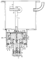
- a matching unit 2 is accommodated in a laser housing 1.
- the adapter unit 2 consists of an L-C element, an inductance being formed by the entire length of the RF feed and discharge to and from the gas discharge space, not shown in the drawing.
- the RF feed line is designed as an inner conductor 3, which is composed of a plug inner contact 4, a bolt 5, a capacitor electrode cylinder 6 and an inner conductor 7 that is variable in its electrically effective length and is connected via a link 8 to a laser electrode connection 9 and opposite it is displaceable in the axial direction.
- the end face of the capacitor electrode cylinder 6 is connected to the variable inner conductor 7 and by an insulating part 12 made of plastic, preferably made of Teflon, opposite an end plate 13 of the outer conductor 10 insulated and mechanically supported against this end plate 13.
- the outer conductor 10 is designed to be displaceable in the axial direction with respect to the laser housing 1 and forms a high-frequency-tight seal with the laser housing 1.
- the end plate 13 is connected to the outer cylinder 14, which projects beyond the capacitor electrode cylinder 6 in the axial direction and is completed via an outer plate 17 and an adjacent outer tube 24.
- the outer tube 24 is connected in its end region to the outer contact ring 25 and is supported against the inner conductor 3 via an insulating disk 26.
- the external contact ring 25 is used to make contact with an external contact of a coaxial connector, not shown, whose shielded contact contacts the internal connector contact 4 of the inner conductor 3.
- a slide ring 27 is arranged to be displaceable in the axial direction.
- the slide ring 27 is supported with the outer cylinder 14 via contact springs and separated from the inner conductor 3 by a dielectric cylinder 28.
- the dielectric cylinder 28 rests on an insulating flange 19, which is preferably made of Teflon.
- the insulating flange 19 encloses an insulating cylinder 20, which is preferably made of ceramic and extends to the capacitor electrode cylinder 6.
- the dielectric cylinder 28 adjoins a stop ring 22 of the insulating part 12, the stop ring 22 serving as a stop for the sliding possibility of the slide ring 27.
- the slide ring 27 is adjusted from the outside by moving bolts 29 in the direction of arrow B.
- the bolts 29 can be fixed in relation to the outer plate 17 and then separated, since readjustment is not provided.
- the end plate 13 can also be fixed relative to the laser housing 1.
- the insulating cylinder 20 is arranged in an extension of the outer conductor 24 between the outer plate 17 and the capacitor electrode cylinder 6 and presses the capacitor electrode cylinder 6 against the insulating part 12 via a corrugated spring 21 and this against the end plate 13.
Landscapes
- Physics & Mathematics (AREA)
- Electromagnetism (AREA)
- Engineering & Computer Science (AREA)
- Plasma & Fusion (AREA)
- Optics & Photonics (AREA)
- Lasers (AREA)
Applications Claiming Priority (2)
| Application Number | Priority Date | Filing Date | Title |
|---|---|---|---|
| DE4121306 | 1991-06-27 | ||
| DE4121306 | 1991-06-27 |
Publications (2)
| Publication Number | Publication Date |
|---|---|
| EP0520249A1 true EP0520249A1 (fr) | 1992-12-30 |
| EP0520249B1 EP0520249B1 (fr) | 1996-02-28 |
Family
ID=6434909
Family Applications (1)
| Application Number | Title | Priority Date | Filing Date |
|---|---|---|---|
| EP92109852A Expired - Lifetime EP0520249B1 (fr) | 1991-06-27 | 1992-06-11 | Laser à haute puissance excité par haute fréquence, en particulier laser CO2 à guide à ruban |
Country Status (3)
| Country | Link |
|---|---|
| US (1) | US5245625A (fr) |
| EP (1) | EP0520249B1 (fr) |
| DE (1) | DE59205437D1 (fr) |
Cited By (1)
| Publication number | Priority date | Publication date | Assignee | Title |
|---|---|---|---|---|
| EP0590343A1 (fr) * | 1992-09-30 | 1994-04-06 | CARL ZEISS JENA GmbH | Laser excité en haute fréquence à haute puissance en particulier laser à ruban à CO2 |
Families Citing this family (8)
| Publication number | Priority date | Publication date | Assignee | Title |
|---|---|---|---|---|
| US6822553B1 (en) * | 1985-10-16 | 2004-11-23 | Ge Interlogix, Inc. | Secure entry system with radio reprogramming |
| US6198758B1 (en) | 1999-12-27 | 2001-03-06 | Synrad, Inc. | Laser with heat transfer system and method |
| US6198759B1 (en) | 1999-12-27 | 2001-03-06 | Synrad, Inc. | Laser system and method for beam enhancement |
| US6195379B1 (en) | 1999-12-27 | 2001-02-27 | Synrad, Inc. | Laser assembly system and method |
| US6614826B1 (en) | 2000-05-05 | 2003-09-02 | Synrad, Inc. | Laser system and method for gain medium with output beam transverse profile tailoring longitudinal strips |
| US6879616B2 (en) * | 2003-01-24 | 2005-04-12 | Trumpf, Inc. | Diffusion-cooled laser system |
| JP4185958B1 (ja) * | 2007-06-11 | 2008-11-26 | ファナック株式会社 | ガスレーザ装置の立ち上げ方法及びガスレーザ装置 |
| RU2438220C2 (ru) * | 2008-02-26 | 2011-12-27 | Валерий Афанасьевич Свиридов | Газоразрядный импульсный источник оптического излучения |
Citations (3)
| Publication number | Priority date | Publication date | Assignee | Title |
|---|---|---|---|---|
| GB2060989A (en) * | 1979-09-24 | 1981-05-07 | Laakmann K D | Rf-excited waveguide gas laser |
| EP0243592A2 (fr) * | 1986-04-29 | 1987-11-04 | Elcede Gmbh | Laser à gaz à excitation haute-fréquence |
| EP0305893A2 (fr) * | 1987-08-31 | 1989-03-08 | Deutsches Zentrum für Luft- und Raumfahrt e.V. | Laser de haute puissance à guide d'onde en forme de bande |
Family Cites Families (1)
| Publication number | Priority date | Publication date | Assignee | Title |
|---|---|---|---|---|
| US5164952A (en) * | 1990-09-26 | 1992-11-17 | Siemens Aktiengesellschaft | Electrically pumped gas laser suitable for high input power |
-
1992
- 1992-06-11 EP EP92109852A patent/EP0520249B1/fr not_active Expired - Lifetime
- 1992-06-11 DE DE59205437T patent/DE59205437D1/de not_active Expired - Fee Related
- 1992-06-24 US US07/903,500 patent/US5245625A/en not_active Expired - Fee Related
Patent Citations (3)
| Publication number | Priority date | Publication date | Assignee | Title |
|---|---|---|---|---|
| GB2060989A (en) * | 1979-09-24 | 1981-05-07 | Laakmann K D | Rf-excited waveguide gas laser |
| EP0243592A2 (fr) * | 1986-04-29 | 1987-11-04 | Elcede Gmbh | Laser à gaz à excitation haute-fréquence |
| EP0305893A2 (fr) * | 1987-08-31 | 1989-03-08 | Deutsches Zentrum für Luft- und Raumfahrt e.V. | Laser de haute puissance à guide d'onde en forme de bande |
Non-Patent Citations (1)
| Title |
|---|
| REVIEW OF SCIENTIFIC INSTRUMENTS Bd. 55, Nr. 10, Oktober 1984, NEW-YORK Seiten 1539 - 1541; R.L.SINCLAIR ET AL.: 'RADIO FREQUENCY EXCITED CO2 WAVEGUIDE LASERS' * |
Cited By (1)
| Publication number | Priority date | Publication date | Assignee | Title |
|---|---|---|---|---|
| EP0590343A1 (fr) * | 1992-09-30 | 1994-04-06 | CARL ZEISS JENA GmbH | Laser excité en haute fréquence à haute puissance en particulier laser à ruban à CO2 |
Also Published As
| Publication number | Publication date |
|---|---|
| DE59205437D1 (de) | 1996-04-04 |
| EP0520249B1 (fr) | 1996-02-28 |
| US5245625A (en) | 1993-09-14 |
Similar Documents
| Publication | Publication Date | Title |
|---|---|---|
| EP1337001B1 (fr) | Dispositif pour la transmission sans contact des signaux électriques et/ou énergie | |
| DE69501782T2 (de) | Überspannungsableiter für koaxialübertragungsleitung | |
| DE857087C (de) | Anschlussglied zum Anschliessen einer koaxialen Leitung oder zum Verbinden zweier koaxialer Leitungen | |
| EP0978157B1 (fr) | Conducteur a impulsions electromagnetiques a large bande | |
| EP1516390B1 (fr) | Dispositif parafoudre et filtre antiparasite | |
| EP0267403A2 (fr) | Circuit capacitif séparateur | |
| DE69625054T2 (de) | Antennenanordnung | |
| WO2002035659A1 (fr) | Systeme de filtrage antiparasite et de paratonnerre | |
| EP0855756B1 (fr) | Parafouder EMP | |
| DE3781146T2 (de) | Hf-entladungsangeregter laser. | |
| EP0520249B1 (fr) | Laser à haute puissance excité par haute fréquence, en particulier laser CO2 à guide à ruban | |
| DE2828927C2 (de) | Mechanisch abstimmbarer koaxialer Impatt-Oszillator | |
| DE3731394C2 (de) | Hochfrequenz-Entstörfilter für eine an eine Leitung anzuschließende Schaltung, insbesondere für Zweidraht-Sensoren | |
| EP0590343B1 (fr) | Laser excité en haute fréquence à haute puissance en particulier laser à ruban à CO2 | |
| DE10010936B4 (de) | Antenne | |
| DE1903518B2 (de) | Hochfrequenzoszillator | |
| EP4342032A1 (fr) | Câble préfabriqué, agencement de connecteur de fiche de câble et connexion de fiche électrique | |
| DE1950596A1 (de) | Elektronische Abstimmvorrichtung fuer elektromagnetischen Resonator | |
| DE2253710A1 (de) | Festkoerper-mikrowellenoszillator | |
| DE3833696C2 (de) | Signalverarbeitungsvorrichtung und Verfahren zum Ausdehnen des flachen Frequenzgangs einer Komponente | |
| EP2625933A1 (fr) | Dispositif hf et accélérateur doté d'un tel dispositif hf | |
| DE914638C (de) | Kopplungselement fuer die UEbertragung einer elektrischen Schwingung sehr hoher Frequenz | |
| DE2240565C3 (de) | Mikrowellenanordnung | |
| DE4329550A1 (de) | Gasentladungslaser | |
| DE102023101789A1 (de) | Niederimpedanz-Hochstromkoaxialleitung für ein Plasmaprozessversorgungssystem und ein Plasmaprozesssystem sowie ein Verfahren zum Betreiben eines Plasmaprozesssystems |
Legal Events
| Date | Code | Title | Description |
|---|---|---|---|
| PUAI | Public reference made under article 153(3) epc to a published international application that has entered the european phase |
Free format text: ORIGINAL CODE: 0009012 |
|
| AK | Designated contracting states |
Kind code of ref document: A1 Designated state(s): DE FR GB IT |
|
| 17P | Request for examination filed |
Effective date: 19930618 |
|
| 17Q | First examination report despatched |
Effective date: 19931220 |
|
| RAP1 | Party data changed (applicant data changed or rights of an application transferred) |
Owner name: CARL ZEISS JENA GMBH |
|
| GRAA | (expected) grant |
Free format text: ORIGINAL CODE: 0009210 |
|
| AK | Designated contracting states |
Kind code of ref document: B1 Designated state(s): DE FR GB IT |
|
| PG25 | Lapsed in a contracting state [announced via postgrant information from national office to epo] |
Ref country code: IT Free format text: LAPSE BECAUSE OF FAILURE TO SUBMIT A TRANSLATION OF THE DESCRIPTION OR TO PAY THE FEE WITHIN THE PRE;WARNING: LAPSES OF ITALIAN PATENTS WITH EFFECTIVE DATE BEFORE 2007 MAY HAVE OCCURRED AT ANY TIME BEFORE 2007. THE CORRECT EFFECTIVE DATE MAY BE DIFFERENT FROM THE ONE RECORDED.SCRIBED TIME-LIMIT Effective date: 19960228 Ref country code: FR Effective date: 19960228 |
|
| REF | Corresponds to: |
Ref document number: 59205437 Country of ref document: DE Date of ref document: 19960404 |
|
| GBT | Gb: translation of ep patent filed (gb section 77(6)(a)/1977) |
Effective date: 19960509 |
|
| EN | Fr: translation not filed | ||
| PGFP | Annual fee paid to national office [announced via postgrant information from national office to epo] |
Ref country code: GB Payment date: 19960805 Year of fee payment: 5 |
|
| PLBE | No opposition filed within time limit |
Free format text: ORIGINAL CODE: 0009261 |
|
| STAA | Information on the status of an ep patent application or granted ep patent |
Free format text: STATUS: NO OPPOSITION FILED WITHIN TIME LIMIT |
|
| 26N | No opposition filed | ||
| PG25 | Lapsed in a contracting state [announced via postgrant information from national office to epo] |
Ref country code: DE Effective date: 19970301 |
|
| PG25 | Lapsed in a contracting state [announced via postgrant information from national office to epo] |
Ref country code: GB Free format text: LAPSE BECAUSE OF NON-PAYMENT OF DUE FEES Effective date: 19970611 |
|
| GBPC | Gb: european patent ceased through non-payment of renewal fee |
Effective date: 19970611 |