EP0520249A1 - High frequency excited laser for high input power, in particular CO2 slab waveguide laser - Google Patents
High frequency excited laser for high input power, in particular CO2 slab waveguide laser Download PDFInfo
- Publication number
- EP0520249A1 EP0520249A1 EP92109852A EP92109852A EP0520249A1 EP 0520249 A1 EP0520249 A1 EP 0520249A1 EP 92109852 A EP92109852 A EP 92109852A EP 92109852 A EP92109852 A EP 92109852A EP 0520249 A1 EP0520249 A1 EP 0520249A1
- Authority
- EP
- European Patent Office
- Prior art keywords
- laser
- outer conductor
- inner conductor
- frequency
- conductor
- Prior art date
- Legal status (The legal status is an assumption and is not a legal conclusion. Google has not performed a legal analysis and makes no representation as to the accuracy of the status listed.)
- Granted
Links
Images
Classifications
-
- H—ELECTRICITY
- H01—ELECTRIC ELEMENTS
- H01S—DEVICES USING THE PROCESS OF LIGHT AMPLIFICATION BY STIMULATED EMISSION OF RADIATION [LASER] TO AMPLIFY OR GENERATE LIGHT; DEVICES USING STIMULATED EMISSION OF ELECTROMAGNETIC RADIATION IN WAVE RANGES OTHER THAN OPTICAL
- H01S3/00—Lasers, i.e. devices using stimulated emission of electromagnetic radiation in the infrared, visible or ultraviolet wave range
- H01S3/09—Processes or apparatus for excitation, e.g. pumping
- H01S3/097—Processes or apparatus for excitation, e.g. pumping by gas discharge of a gas laser
- H01S3/0975—Processes or apparatus for excitation, e.g. pumping by gas discharge of a gas laser using inductive or capacitive excitation
-
- H—ELECTRICITY
- H01—ELECTRIC ELEMENTS
- H01S—DEVICES USING THE PROCESS OF LIGHT AMPLIFICATION BY STIMULATED EMISSION OF RADIATION [LASER] TO AMPLIFY OR GENERATE LIGHT; DEVICES USING STIMULATED EMISSION OF ELECTROMAGNETIC RADIATION IN WAVE RANGES OTHER THAN OPTICAL
- H01S3/00—Lasers, i.e. devices using stimulated emission of electromagnetic radiation in the infrared, visible or ultraviolet wave range
- H01S3/02—Constructional details
- H01S3/03—Constructional details of gas laser discharge tubes
- H01S3/0315—Waveguide lasers
Definitions
- the present invention relates to an RF-excited laser for high input powers, in particular a CO2 ribbon laser according to the preamble of claim 1.
- a CO2 ribbon laser according to the preamble of claim 1.
- Such a laser is described in the German application P 40 30 442.6.
- a stripline laser is known from DE-OS 37 29 053.
- a matching unit is used for higher power, high frequency excited lasers, e.g. at an input power of at least one kW, for transforming the impedance of the electrons exciting the plasma to the output impedance of the generator, which is generally 50 ohms, at a predetermined frequency.
- high frequency excited lasers e.g. at an input power of at least one kW
- the output impedance of the generator which is generally 50 ohms
- the object on which the present invention is based consists in a compact construction of an adapter and at the same time a minimization of the current load.
- the LC element acts as a resonance transformer at the specified frequency.
- the special design ensures a high-frequency-tight termination of the laser and a high-frequency-tight connection to a high-frequency cable.
- the inner conductor advantageously forms an area with an enlarged diameter, the capacitance of the capacitor being determined by the axial position of the sliding ring in relation to this area.
- Optimal space utilization of the existing laser housing is made possible by designing the outer conductor coaxially with the laser housing and displaceable in relation to it in the axial direction, by guiding the inner conductor through an end plate of the outer conductor in an insulated manner, by the inner conductor behind this end plate using a link which is movable in the axial direction contains and by the axial position of the outer conductor relative to the housing determines the set inductance.
- the outer conductor advantageously encloses the inner conductor completely up to a plug connection for a coaxial plug and adjoins the housing wall in a highly frequency-tight manner. In this way, the laser can be connected to a connecting cable in a high-frequency-tight manner in a simple manner.
- a matching unit 2 is accommodated in a laser housing 1.
- the adapter unit 2 consists of an L-C element, an inductance being formed by the entire length of the RF feed and discharge to and from the gas discharge space, not shown in the drawing.
- the RF feed line is designed as an inner conductor 3, which is composed of a plug inner contact 4, a bolt 5, a capacitor electrode cylinder 6 and an inner conductor 7 that is variable in its electrically effective length and is connected via a link 8 to a laser electrode connection 9 and opposite it is displaceable in the axial direction.
- the end face of the capacitor electrode cylinder 6 is connected to the variable inner conductor 7 and by an insulating part 12 made of plastic, preferably made of Teflon, opposite an end plate 13 of the outer conductor 10 insulated and mechanically supported against this end plate 13.
- the outer conductor 10 is designed to be displaceable in the axial direction with respect to the laser housing 1 and forms a high-frequency-tight seal with the laser housing 1.
- the end plate 13 is connected to the outer cylinder 14, which projects beyond the capacitor electrode cylinder 6 in the axial direction and is completed via an outer plate 17 and an adjacent outer tube 24.
- the outer tube 24 is connected in its end region to the outer contact ring 25 and is supported against the inner conductor 3 via an insulating disk 26.
- the external contact ring 25 is used to make contact with an external contact of a coaxial connector, not shown, whose shielded contact contacts the internal connector contact 4 of the inner conductor 3.
- a slide ring 27 is arranged to be displaceable in the axial direction.
- the slide ring 27 is supported with the outer cylinder 14 via contact springs and separated from the inner conductor 3 by a dielectric cylinder 28.
- the dielectric cylinder 28 rests on an insulating flange 19, which is preferably made of Teflon.
- the insulating flange 19 encloses an insulating cylinder 20, which is preferably made of ceramic and extends to the capacitor electrode cylinder 6.
- the dielectric cylinder 28 adjoins a stop ring 22 of the insulating part 12, the stop ring 22 serving as a stop for the sliding possibility of the slide ring 27.
- the slide ring 27 is adjusted from the outside by moving bolts 29 in the direction of arrow B.
- the bolts 29 can be fixed in relation to the outer plate 17 and then separated, since readjustment is not provided.
- the end plate 13 can also be fixed relative to the laser housing 1.
- the insulating cylinder 20 is arranged in an extension of the outer conductor 24 between the outer plate 17 and the capacitor electrode cylinder 6 and presses the capacitor electrode cylinder 6 against the insulating part 12 via a corrugated spring 21 and this against the end plate 13.
Landscapes
- Physics & Mathematics (AREA)
- Electromagnetism (AREA)
- Engineering & Computer Science (AREA)
- Plasma & Fusion (AREA)
- Optics & Photonics (AREA)
- Lasers (AREA)
Abstract
Für die Zuführung einer Hochfrequenzenergie hoher Leistung zu einem Laser wird eine Anpaßeinheit (2) für den Wellenwiderstand in den Laser integriert, wobei die Anpaßeinheit (2) ein L-C-Glied enthält, bei dem die Induktivität L und die Kapazität C variabel sind, bei dem die Induktivität durch eine Veränderung der Länge der galvanisch leitenden Teile einer Hochfrequenzzuleitung und einer Hochfrequenzableitung einstellbar ist, wobei der Kondensator durch einen Außenleiter (10) und einen zu diesem koaxialen Innenleiter (3) aufgebaut ist und wobei mit dem Außenleiter (10) ein koaxialer, in axialer Richtung von außen bewegbarer Gleitring (27) in Verbindung steht, welcher an einen Dielektrikumszylinder (28) zwischen dem Außenleiter (10) und dem Innenleiter (3) angrenzt, und wobei der Außenleiter (10) den Innenleiter (3) trägt.For the supply of high-frequency energy of high power to a laser, an adapter unit (2) for the wave resistance is integrated into the laser, the adapter unit (2) including an LC element in which the inductance L and the capacitance C are variable, in which the inductance can be adjusted by changing the length of the galvanically conductive parts of a high-frequency lead and a high-frequency lead, the capacitor being constructed by an outer conductor (10) and an inner conductor (3) coaxial with it, and wherein the outer conductor (10) is a coaxial, In the axial direction from the outside movable slide ring (27) is connected, which adjoins a dielectric cylinder (28) between the outer conductor (10) and the inner conductor (3), and wherein the outer conductor (10) carries the inner conductor (3).
Der erfindungsgemäße hochfrequenzangeregte Laser ist vorgesehen für CO₂-Bandleiterlaser.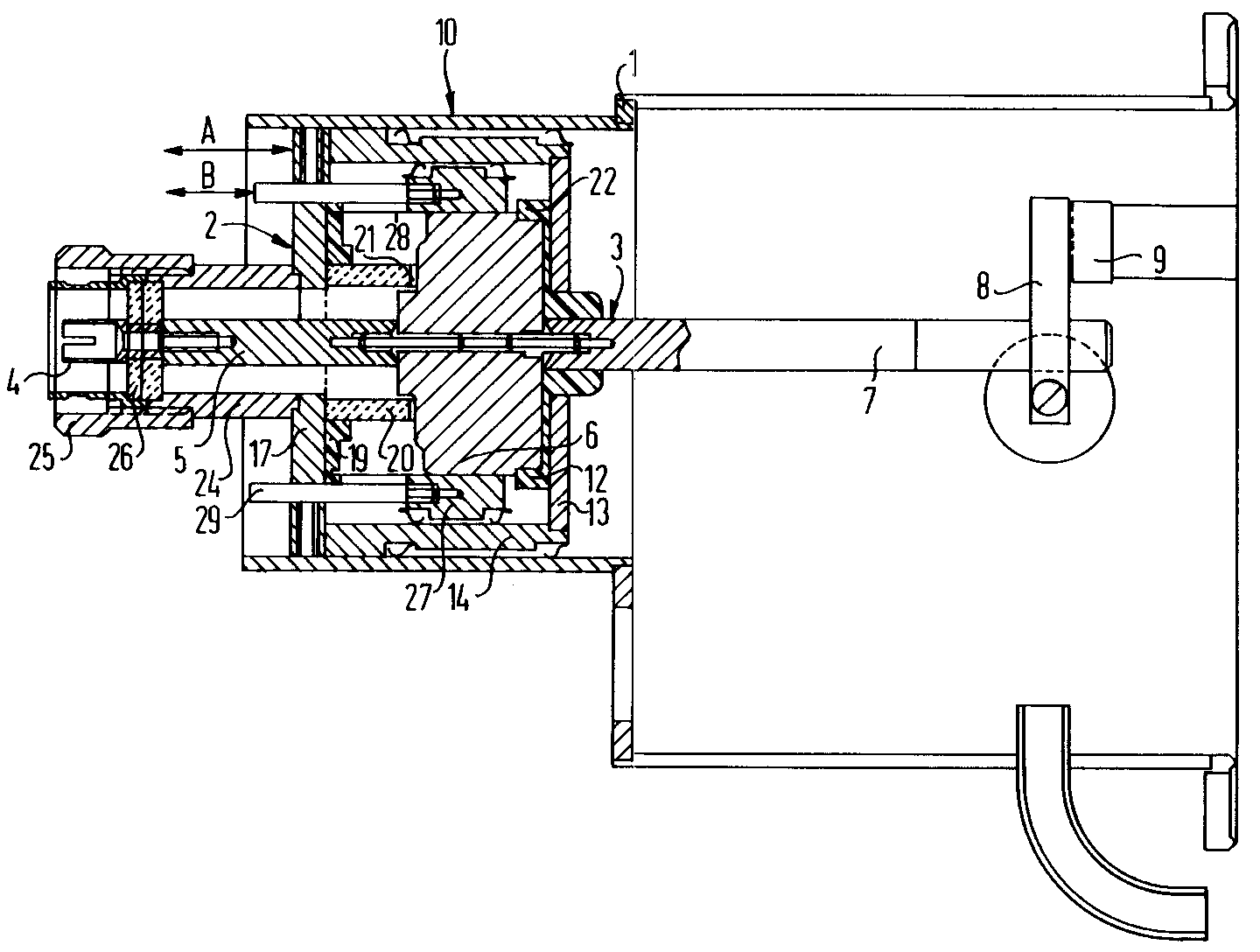
Description
Die vorliegende Erfindung betrifft einen HF-angeregten Laser für hohe Eingangsleistungen, insbesondere einen CO₂-Bandleiterlaser nach dem Oberbegriff des Patentanspruchs 1. Ein derartiger Laser ist in der deutschen Anmeldung P 40 30 442.6 beschrieben. Außerdem ist ein Bandleiterlaser aus der DE-OS 37 29 053 bekannt.The present invention relates to an RF-excited laser for high input powers, in particular a CO₂ ribbon laser according to the preamble of claim 1. Such a laser is described in the German application P 40 30 442.6. In addition, a stripline laser is known from DE-OS 37 29 053.
Eine Anpaßeinheit dient bei hochfrequenzangeregten Lasern höherer Leistung, z.B. bei einer Eingangsleistung von mindestens einem kW, zur Transformation der Inpedanz der das Plasma anregenden Elektronen auf die Ausgangsimpedanz des Generators, die in der Regel 50 Ohm beträgt, bei einer vorgegebenen Frequenz. Hierzu wurden bisher entweder zwei Kurzschlußleitungen im λ/4 Abstand in die Eingangsleitung geschaltet oder ein π-Glied mit fester Längsinduktivität und zwei variablen Querkapazitäten eingesetzt. Die Kurzschlußleitungen bedingen jedoch hohe Ströme und hohe Spannungen auf den 50-Ohm-Leitungen, Während das π-Glied großvolumig aufgebaut werden muß.A matching unit is used for higher power, high frequency excited lasers, e.g. at an input power of at least one kW, for transforming the impedance of the electrons exciting the plasma to the output impedance of the generator, which is generally 50 ohms, at a predetermined frequency. To this end, either two short-circuit lines with a λ / 4 spacing have been connected to the input line or a π element with a fixed series inductance and two variable transverse capacitances has been used. The short-circuit lines, however, require high currents and high voltages on the 50-ohm lines, while the π element has to be constructed with a large volume.
Demgegenüber besteht die Aufgabe, die der vorliegenden Erfindung zugrundeliegt, in einem kompakten Aufbau eines Anpaßgliedes und gleichzeitig einer Minimierung der Strombelastung.In contrast, the object on which the present invention is based consists in a compact construction of an adapter and at the same time a minimization of the current load.
Diese Aufgabe wird bei einem Laser gemäß dem Oberbegriff durch die kennzeichnenden Merkmale des Patentanspruchs 1 gelöst.This object is achieved in a laser according to the preamble by the characterizing features of patent claim 1.
Das L-C-Glied wirkt hier bei der vorgegebenen Frequenz als Resonanztransformator. Der spezielle Aufbau gewährleistet einen hochfrequenzdichten Abschluß des Lasers und einen hochfrequenzdichten Anschluß an ein Hochfrequenzkabel.The LC element acts as a resonance transformer at the specified frequency. The special design ensures a high-frequency-tight termination of the laser and a high-frequency-tight connection to a high-frequency cable.
Vorteilhaft bildet der Innenleiter einen Bereich mit einem vergrößerten Durchmesser, wobei die Kapazität des Kondensators durch die axiale Lage des Gleitringes zu diesem Bereich bestimmt ist.The inner conductor advantageously forms an area with an enlarged diameter, the capacitance of the capacitor being determined by the axial position of the sliding ring in relation to this area.
Eine optimale Raumausnutzung des vorhandenen Lasergehäuses ist ermöglicht, indem der Außenleiter koaxial zum Lasergehäuse und gegenüber diesem in axialer Richtung verschiebbar gestaltet ist, indem der Innenleiter isoliert durch eine Stirnplatte des Außenleiters hindurch geführt ist, indem der Innenleiter hinter dieser Stirnplatte ein in axialer Richtung bewegliches Bindeglied enthält und indem die axiale Lage des Außenleiters gegenüber dem Gehäuse die eingestellte Induktivität bestimmt. Dabei umschließt vorteilhaft der Außenleiter den Innenleiter bis zu einem Steckeranschluß für einen Koaxialstecker hin vollständig und grenzt an die Gehäusewand hochfrenquenzdicht an. So ist auf einfache Weise der Laser hochfrequenzdicht mit einem Anschlußkabel zu verbinden.Optimal space utilization of the existing laser housing is made possible by designing the outer conductor coaxially with the laser housing and displaceable in relation to it in the axial direction, by guiding the inner conductor through an end plate of the outer conductor in an insulated manner, by the inner conductor behind this end plate using a link which is movable in the axial direction contains and by the axial position of the outer conductor relative to the housing determines the set inductance. The outer conductor advantageously encloses the inner conductor completely up to a plug connection for a coaxial plug and adjoins the housing wall in a highly frequency-tight manner. In this way, the laser can be connected to a connecting cable in a high-frequency-tight manner in a simple manner.
Die Erfindung Wird nun anhand einer Figur näher erläutert. Sie ist nicht auf das in der Figur gezeigte Beispiel beschränkt.The invention will now be explained in more detail with reference to a figure. It is not limited to the example shown in the figure.
In einem Lasergehäuse 1 ist eine Anpaßeinheit 2 untergebracht. Die Anpaßeinheit 2 besteht aus einem L-C-Glied, wobei eine Induktivität durch die gesamte Länge der HF-Zu- und -Ableitung zum und vom in der Zeichnung nicht dargestellten Gasentladungsraum gebildet ist. Die HF-Zuleitung ist als Innenleiter 3 ausgebildet, welcher sich aus einem Steckerinnenkontakt 4, einem Bolzen 5, einem Kondensatorelektrodenzylinder 6 und einem in seiner elektrisch wirksamen Länge variablen Innenleiter 7 zusammensetzt und über ein Bindeglied 8 mit einem Laserelektrodenanschluß 9 in Verbindung steht und gegenüber diesem in axialer Richtung verschiebbar ist.A matching unit 2 is accommodated in a laser housing 1. The adapter unit 2 consists of an L-C element, an inductance being formed by the entire length of the RF feed and discharge to and from the gas discharge space, not shown in the drawing. The RF feed line is designed as an inner conductor 3, which is composed of a plug inner contact 4, a bolt 5, a
Die Stirnseite des Kondensatorelektrodenzylinders 6 ist mit dem variablen Innenleiter 7 verbunden und durch ein Isolierteil 12 aus Kunststoff, vorzugsweise aus Teflon gegenüber einer Stirnplatte 13 des Außenleiters 10 isoliert und gegen diese Stirnplatte 13 mechanisch abgestützt. Der Außenleiter 10 ist gegenüber dem Lasergehäuse 1 in axialer Richtung verschiebbar ausgebildet und bildet zum Lasergehäuse 1 einen hochfrequenzdichten Abschluß.The end face of the
Die Stirnplatte 13 ist mit dem Außenzylinder 14 verbunden, welcher den Kondensatorelektrodenzylinder 6 in axialer Richtung überragt und über eine Außenplatte 17 und ein daran angrenzendes Außenrohr 24 vervollständigt wird. Das Außenrohr 24 ist in seinem Endbereich mit dem Außenkontaktring 25 verbunden und über eine Isolierscheibe 26 gegen den Innenleiter 3 abgestützt. Der Außenkontaktring 25 dient zur Kontaktgabe gegenüber einem Außenkontakt eines nicht dargestellten Koaxialsteckers, dessen abgeschirmter Kontakt den Steckerinnenkontakt 4 des Innenleiters 3 kontaktiert.The
Im Außenzylinder 14 ist ein Gleitring 27 in axialer Richtung verschiebbar angeordnet. Der Gleitring 27 ist mit dem Außenzylinder 14 über Kontaktfedern abgestützt und vom Innenleiter 3 durch einen Dielektrikumszylinder 28 getrennt. Der Dielektrikumszylinder 28 liegt auf einem Isolierstoff-Flansch 19 auf, der vorzugsweise aus Teflon besteht. Der Isolierstofflansch 19 umschließt einen Isolierzylinder 20, der vorzugsweise aus Keramik besteht und sich zum Kondensatorelektrodenzylinder 6 erstreckt. Der Dielektrikumszylinder 28 grenzt an einen Anschlagring 22 des Isolierteiles 12 an, wobei der Anschlagring 22 als Anschlag für die Verschiebemöglichkeit des Gleitringes 27 dient. Der Gleitring 27 wird von außen durch Verschiebung von Bolzen 29 in Pfeilrichtung B eingestellt. Nach dem Abgleich können die Bolzen 29 gegenüber der Außenplatte 17 fixiert und dann abgetrennt werden, da eine Nachjustierung nicht vorgesehen ist. Nach dem Abgleich der Induktivität durch Verschieben der gesamten Anpaßeinheit 2 in Pfeilrichtung A kann auch die Stirnplatte 13 gegenüber dem Lasergehäuse 1 fixiert werden.In the
Der Isolierzylinder 20 ist in Verlängerung des Außenleiters 24 zwischen der Außenplatte 17 und dem Kondensatorelektrodenzylinder 6 angeordnet und drückt über eine Wellfeder 21 den Kondensatorelektrodenzylinder 6 gegen das Isolierteil 12 und dieses gegen die Stirnplatte 13.The insulating cylinder 20 is arranged in an extension of the
Claims (4)
Applications Claiming Priority (2)
| Application Number | Priority Date | Filing Date | Title |
|---|---|---|---|
| DE4121306 | 1991-06-27 | ||
| DE4121306 | 1991-06-27 |
Publications (2)
| Publication Number | Publication Date |
|---|---|
| EP0520249A1 true EP0520249A1 (en) | 1992-12-30 |
| EP0520249B1 EP0520249B1 (en) | 1996-02-28 |
Family
ID=6434909
Family Applications (1)
| Application Number | Title | Priority Date | Filing Date |
|---|---|---|---|
| EP92109852A Expired - Lifetime EP0520249B1 (en) | 1991-06-27 | 1992-06-11 | High frequency excited laser for high input power, in particular CO2 slab waveguide laser |
Country Status (3)
| Country | Link |
|---|---|
| US (1) | US5245625A (en) |
| EP (1) | EP0520249B1 (en) |
| DE (1) | DE59205437D1 (en) |
Cited By (1)
| Publication number | Priority date | Publication date | Assignee | Title |
|---|---|---|---|---|
| EP0590343A1 (en) * | 1992-09-30 | 1994-04-06 | CARL ZEISS JENA GmbH | High power high frequency excited laser, in particular CO2 slab laser |
Families Citing this family (8)
| Publication number | Priority date | Publication date | Assignee | Title |
|---|---|---|---|---|
| US6822553B1 (en) * | 1985-10-16 | 2004-11-23 | Ge Interlogix, Inc. | Secure entry system with radio reprogramming |
| US6198758B1 (en) | 1999-12-27 | 2001-03-06 | Synrad, Inc. | Laser with heat transfer system and method |
| US6198759B1 (en) | 1999-12-27 | 2001-03-06 | Synrad, Inc. | Laser system and method for beam enhancement |
| US6195379B1 (en) | 1999-12-27 | 2001-02-27 | Synrad, Inc. | Laser assembly system and method |
| US6614826B1 (en) | 2000-05-05 | 2003-09-02 | Synrad, Inc. | Laser system and method for gain medium with output beam transverse profile tailoring longitudinal strips |
| US6879616B2 (en) * | 2003-01-24 | 2005-04-12 | Trumpf, Inc. | Diffusion-cooled laser system |
| JP4185958B1 (en) * | 2007-06-11 | 2008-11-26 | ファナック株式会社 | Method for starting up gas laser device and gas laser device |
| RU2438220C2 (en) * | 2008-02-26 | 2011-12-27 | Валерий Афанасьевич Свиридов | Gas-discharge pulse optical source |
Citations (3)
| Publication number | Priority date | Publication date | Assignee | Title |
|---|---|---|---|---|
| GB2060989A (en) * | 1979-09-24 | 1981-05-07 | Laakmann K D | Rf-excited waveguide gas laser |
| EP0243592A2 (en) * | 1986-04-29 | 1987-11-04 | Elcede Gmbh | Radio-frequency excited gas laser |
| EP0305893A2 (en) * | 1987-08-31 | 1989-03-08 | Deutsches Zentrum für Luft- und Raumfahrt e.V. | High-power strip-guide laser |
Family Cites Families (1)
| Publication number | Priority date | Publication date | Assignee | Title |
|---|---|---|---|---|
| US5164952A (en) * | 1990-09-26 | 1992-11-17 | Siemens Aktiengesellschaft | Electrically pumped gas laser suitable for high input power |
-
1992
- 1992-06-11 EP EP92109852A patent/EP0520249B1/en not_active Expired - Lifetime
- 1992-06-11 DE DE59205437T patent/DE59205437D1/en not_active Expired - Fee Related
- 1992-06-24 US US07/903,500 patent/US5245625A/en not_active Expired - Fee Related
Patent Citations (3)
| Publication number | Priority date | Publication date | Assignee | Title |
|---|---|---|---|---|
| GB2060989A (en) * | 1979-09-24 | 1981-05-07 | Laakmann K D | Rf-excited waveguide gas laser |
| EP0243592A2 (en) * | 1986-04-29 | 1987-11-04 | Elcede Gmbh | Radio-frequency excited gas laser |
| EP0305893A2 (en) * | 1987-08-31 | 1989-03-08 | Deutsches Zentrum für Luft- und Raumfahrt e.V. | High-power strip-guide laser |
Non-Patent Citations (1)
| Title |
|---|
| REVIEW OF SCIENTIFIC INSTRUMENTS Bd. 55, Nr. 10, Oktober 1984, NEW-YORK Seiten 1539 - 1541; R.L.SINCLAIR ET AL.: 'RADIO FREQUENCY EXCITED CO2 WAVEGUIDE LASERS' * |
Cited By (1)
| Publication number | Priority date | Publication date | Assignee | Title |
|---|---|---|---|---|
| EP0590343A1 (en) * | 1992-09-30 | 1994-04-06 | CARL ZEISS JENA GmbH | High power high frequency excited laser, in particular CO2 slab laser |
Also Published As
| Publication number | Publication date |
|---|---|
| DE59205437D1 (en) | 1996-04-04 |
| EP0520249B1 (en) | 1996-02-28 |
| US5245625A (en) | 1993-09-14 |
Similar Documents
| Publication | Publication Date | Title |
|---|---|---|
| EP1337001B1 (en) | Device for contactless transmission of electrical signals and /or energy | |
| DE69501782T2 (en) | SURGE PROTECTOR FOR COAXIAL TRANSMISSION LINE | |
| DE857087C (en) | Connector for connecting a coaxial line or for connecting two coaxial lines | |
| EP0978157B1 (en) | Wide-band electromagnetic-pulse conductor | |
| EP1516390B1 (en) | Interference filter and lightning conductor device | |
| EP0267403A2 (en) | Capacitive separating circuit | |
| DE69625054T2 (en) | ANTENNA ARRANGEMENT | |
| WO2002035659A1 (en) | Surge protection filter and lightning conductor system | |
| EP0855756B1 (en) | EMP-arrester | |
| DE3781146T2 (en) | HF DISCHARGE-EXCITED LASER. | |
| EP0520249B1 (en) | High frequency excited laser for high input power, in particular CO2 slab waveguide laser | |
| DE2828927C2 (en) | Mechanically tunable coaxial Impatt oscillator | |
| DE3731394C2 (en) | High-frequency interference filter for a circuit to be connected to a line, in particular for two-wire sensors | |
| EP0590343B1 (en) | High power high frequency excited laser, in particular CO2 slab laser | |
| DE10010936B4 (en) | antenna | |
| DE1903518B2 (en) | HIGH FREQUENCY OSCILLATOR | |
| EP4342032A1 (en) | Prefabricated cable, cable plug connector arrangement, and electrical plug connection | |
| DE1950596A1 (en) | Electronic tuning device for electromagnetic resonator | |
| DE2253710A1 (en) | SOLID STATE MICROWAVE OSCILLATOR | |
| DE3833696C2 (en) | Signal processing device and method for expanding the flat frequency response of a component | |
| EP2625933A1 (en) | Rf apparatus and accelerator having such an rf apparatus | |
| DE914638C (en) | Coupling element for the transmission of an electrical oscillation of very high frequency | |
| DE2240565C3 (en) | Microwave array | |
| DE4329550A1 (en) | Gas discharge laser | |
| DE102023101789A1 (en) | Low-impedance high-current coaxial cable for a plasma process supply system and a plasma process system and a method for operating a plasma process system |
Legal Events
| Date | Code | Title | Description |
|---|---|---|---|
| PUAI | Public reference made under article 153(3) epc to a published international application that has entered the european phase |
Free format text: ORIGINAL CODE: 0009012 |
|
| AK | Designated contracting states |
Kind code of ref document: A1 Designated state(s): DE FR GB IT |
|
| 17P | Request for examination filed |
Effective date: 19930618 |
|
| 17Q | First examination report despatched |
Effective date: 19931220 |
|
| RAP1 | Party data changed (applicant data changed or rights of an application transferred) |
Owner name: CARL ZEISS JENA GMBH |
|
| GRAA | (expected) grant |
Free format text: ORIGINAL CODE: 0009210 |
|
| AK | Designated contracting states |
Kind code of ref document: B1 Designated state(s): DE FR GB IT |
|
| PG25 | Lapsed in a contracting state [announced via postgrant information from national office to epo] |
Ref country code: IT Free format text: LAPSE BECAUSE OF FAILURE TO SUBMIT A TRANSLATION OF THE DESCRIPTION OR TO PAY THE FEE WITHIN THE PRE;WARNING: LAPSES OF ITALIAN PATENTS WITH EFFECTIVE DATE BEFORE 2007 MAY HAVE OCCURRED AT ANY TIME BEFORE 2007. THE CORRECT EFFECTIVE DATE MAY BE DIFFERENT FROM THE ONE RECORDED.SCRIBED TIME-LIMIT Effective date: 19960228 Ref country code: FR Effective date: 19960228 |
|
| REF | Corresponds to: |
Ref document number: 59205437 Country of ref document: DE Date of ref document: 19960404 |
|
| GBT | Gb: translation of ep patent filed (gb section 77(6)(a)/1977) |
Effective date: 19960509 |
|
| EN | Fr: translation not filed | ||
| PGFP | Annual fee paid to national office [announced via postgrant information from national office to epo] |
Ref country code: GB Payment date: 19960805 Year of fee payment: 5 |
|
| PLBE | No opposition filed within time limit |
Free format text: ORIGINAL CODE: 0009261 |
|
| STAA | Information on the status of an ep patent application or granted ep patent |
Free format text: STATUS: NO OPPOSITION FILED WITHIN TIME LIMIT |
|
| 26N | No opposition filed | ||
| PG25 | Lapsed in a contracting state [announced via postgrant information from national office to epo] |
Ref country code: DE Effective date: 19970301 |
|
| PG25 | Lapsed in a contracting state [announced via postgrant information from national office to epo] |
Ref country code: GB Free format text: LAPSE BECAUSE OF NON-PAYMENT OF DUE FEES Effective date: 19970611 |
|
| GBPC | Gb: european patent ceased through non-payment of renewal fee |
Effective date: 19970611 |