EP0520114A1 - Interruptable flushing mechanism with garanteed minimum flush - Google Patents
Interruptable flushing mechanism with garanteed minimum flush Download PDFInfo
- Publication number
- EP0520114A1 EP0520114A1 EP91430017A EP91430017A EP0520114A1 EP 0520114 A1 EP0520114 A1 EP 0520114A1 EP 91430017 A EP91430017 A EP 91430017A EP 91430017 A EP91430017 A EP 91430017A EP 0520114 A1 EP0520114 A1 EP 0520114A1
- Authority
- EP
- European Patent Office
- Prior art keywords
- interruptible
- push button
- flushing mechanism
- valve
- mechanism according
- Prior art date
- Legal status (The legal status is an assumption and is not a legal conclusion. Google has not performed a legal analysis and makes no representation as to the accuracy of the status listed.)
- Granted
Links
- 238000011010 flushing procedure Methods 0.000 title claims abstract description 37
- 230000007246 mechanism Effects 0.000 title claims abstract description 35
- XLYOFNOQVPJJNP-UHFFFAOYSA-N water Substances O XLYOFNOQVPJJNP-UHFFFAOYSA-N 0.000 claims abstract description 29
- 230000005540 biological transmission Effects 0.000 claims abstract description 17
- 238000000034 method Methods 0.000 claims abstract description 9
- 125000006850 spacer group Chemical group 0.000 claims description 7
- 238000004891 communication Methods 0.000 claims 2
- 238000007599 discharging Methods 0.000 abstract 1
- 238000003825 pressing Methods 0.000 description 5
- 230000006835 compression Effects 0.000 description 3
- 238000007906 compression Methods 0.000 description 3
- 230000008901 benefit Effects 0.000 description 2
- 230000000295 complement effect Effects 0.000 description 2
- 238000006073 displacement reaction Methods 0.000 description 2
- 239000000463 material Substances 0.000 description 2
- 230000010355 oscillation Effects 0.000 description 2
- 206010028916 Neologism Diseases 0.000 description 1
- 241000135309 Processus Species 0.000 description 1
- 230000003749 cleanliness Effects 0.000 description 1
- 230000007423 decrease Effects 0.000 description 1
- 230000002950 deficient Effects 0.000 description 1
- 238000005192 partition Methods 0.000 description 1
- 230000002093 peripheral effect Effects 0.000 description 1
- 230000001737 promoting effect Effects 0.000 description 1
- 230000000717 retained effect Effects 0.000 description 1
- 230000002747 voluntary effect Effects 0.000 description 1
Images


Classifications
-
- E—FIXED CONSTRUCTIONS
- E03—WATER SUPPLY; SEWERAGE
- E03D—WATER-CLOSETS OR URINALS WITH FLUSHING DEVICES; FLUSHING VALVES THEREFOR
- E03D1/00—Water flushing devices with cisterns ; Setting up a range of flushing devices or water-closets; Combinations of several flushing devices
- E03D1/02—High-level flushing systems
- E03D1/14—Cisterns discharging variable quantities of water also cisterns with bell siphons in combination with flushing valves
- E03D1/142—Cisterns discharging variable quantities of water also cisterns with bell siphons in combination with flushing valves in cisterns with flushing valves
-
- E—FIXED CONSTRUCTIONS
- E03—WATER SUPPLY; SEWERAGE
- E03D—WATER-CLOSETS OR URINALS WITH FLUSHING DEVICES; FLUSHING VALVES THEREFOR
- E03D1/00—Water flushing devices with cisterns ; Setting up a range of flushing devices or water-closets; Combinations of several flushing devices
- E03D1/02—High-level flushing systems
- E03D1/14—Cisterns discharging variable quantities of water also cisterns with bell siphons in combination with flushing valves
- E03D2001/147—Cisterns discharging variable quantities of water also cisterns with bell siphons in combination with flushing valves having provisions for active interruption of flushing
- E03D2001/148—Cisterns discharging variable quantities of water also cisterns with bell siphons in combination with flushing valves having provisions for active interruption of flushing with means to prevent premature closing of flushing valve
Definitions
- the present invention relates to a "interruptable" flushing mechanism, with minimum guaranteed flow, for a toilet flush tank, the "interruptable” neologism meaning: whose action can be interrupted.
- Hunting mechanisms are known (EP-A-0.124.458, EP-A-0.128.847, FR-A-2.591.250, FR-A-2.580.694) comprising a valve movable in axial translation and intended for s '' apply to the edge of the drain orifice provided in the bottom of the flush tank, this valve being mounted at the end or at the bottom of a tubular rod itself secured to a float the function is to keep said valve away from its seat, during the water evacuation or flushing process; these flushing mechanisms further comprising a push button control device and a system for transmitting or lifting the valve actuated by said push button.
- a device for actuating the flow valve comprising a push-button for control integral with a thrust member that can slide axially and connected, by means of a hinge, to a thrust head that can pivot laterally in a limited manner, on either side of its sliding axis, so as to act on one or the other of the two arms of a tilting lever, one of the arms of this lever being attached, by means of remote transmission members, to the flow valve, so that according to the pivoting push head presses on one or the other of the arms of the pivoting lever, an upward pulling action is exerted causing the raising of said valve or a downward pushing action causing the lowering of the latter in the direction of his seat.
- This device has the particular disadvantage of not transmitting axial forces to the tube equipped with the flow valve, so that the longitudinal translation of the tube-flow valve assembly is not perfect, which, of on the one hand, increases the importance of the forces necessary for the displacement of said assembly, especially in the upward direction and, on the other hand, can lead, in the long run, to a misalignment of the movable element of the flushing mechanism and a poor application the valve on its seat promoting the appearance of a leak.
- Another major drawback of this device is that it makes it possible to interrupt the flushing process at any time after having started it, so that the flow of water can be stopped before the bowl is completely cleaned, and that ineffective quantities of water evacuated are wasted, the use of such a device does not, moreover, offer the guarantees of desirable cleanliness and hygiene.
- An object of the present invention is therefore to remedy the aforementioned drawbacks and, more particularly, the shortcoming indicated last.
- this object is achieved thanks to a flushing mechanism comprising a lift chamber arranged in the upper part of said mechanism and in which is housed the float secured in axial translation to the shutter valve of the drain orifice, this lift chamber being supplemented by rapid emptying means comprising at least one member subject to the push button and at least one orifice placed in the bottom or near the bottom of said chamber, these means being placed in the operative position during pressing the push button, and inoperative position when you stop pressing it.
- the base 5 has a central orifice C whose upper circular edge 8 constitutes the seat of the valve 3.
- the base 5 When the flushing mechanism is positioned inside a flushing tank itself fixed on a toilet bowl, the base 5 is fixedly installed, by means of a nut (not shown) screwed onto the threaded lower cylindrical portion 5a of said base, in the orifice 6.
- the central orifice C of the base 5 constitutes the emptying orifice of said tank.
- the seal between the bottom 7 of the reservoir and the seat or bearing face of the base 5 is produced by means of an intermediate annular seal 9 made of rubber or other suitable material.
- the base of the outer envelope 1 and the base 5 are arranged in a complementary manner or provided with complementary joining means allowing them to be rigidly assembled, in a separable manner, while allowing the passage of water between said base and said base.
- the base 5 is, for example, provided with three locking forks 10 spaced 120 degrees and between the branches of which can be engaged and retained the base of the casing 1. Between the locking forks are thus formed large openings 11 , for the passage of water.
- the upper part of the envelope 1 is arranged so as to constitute an auxiliary tank 12.
- the upper part 1a of the envelope 1 constitutes the side wall of this tank, the bottom of which is formed, according to the embodiment illustrated in FIGS. 1 to 4, by a circular wall or partition 13.
- the side wall 1a of the tank 12 is provided with discharge orifices 14 distributed over the periphery of said wall, these orifices being placed above said bottom according to the embodiment illustrated in FIGS. 1 to 6.
- the orifices 14 are disposed approximately in the middle part of the height of the casing 1 and of the flushing mechanism, and at a level which is very clearly below the level where the orifice above the overflow tube is placed. 4, for example about halfway up the latter.
- the float 2 of the flushing mechanism is housed inside the lift chamber 12.
- This float is advantageously constituted by a bell open at its base and closed at its top and this bell is rigidly secured to a spacer tube 15 by means of which it is connected to the valve 3.
- the latter is, for example, constituted by a seal in the form of a circular crown, made of rubber or other similar material, and it is installed in a peripheral groove which has a rigid frame 16 constituting the lower end of the spacer tube 15.
- the mechanism according to the invention further comprises means allowing rapid emptying of the lift chamber 12.
- these means comprise, in addition to the orifices 14 previously described, a shutter constituted by the cylindrical side wall 26 of an auxiliary tank 25 of annular shape, disposed, with an axial displacement capacity, around the spacer tube 15.
- This auxiliary tank 25 is open at its upper part and, its side wall 26 comprises, near from the bottom 25a of said tank orifices 27 whose shape, number and distribution correspond to the shape, number and distribution of the orifices 14, opposite which they can be placed.
- the side wall 2a of the float 2 is housed in the annular auxiliary tank 25, the height of this wall being substantially equal to the height of the internal cylindrical wall 25b of said tank.
- the external side wall 26 of the annular auxiliary tank 25 has a height substantially greater than that of the internal wall 25b of said tank.
- the spacer tube 15 comprises a tubular extension 15a, the upper orifice D of which is placed substantially at the level where the orifice A of the overflow tube 4 is located, when the device is at rest, and preferably slightly at below this level.
- the side wall 26 of the auxiliary tank 25 is rigidly secured to two columns or connecting rods 28 oriented upwards and diametrically opposite.
- Springs 30 acting in compression are arranged around the upper part of the rods 28. These springs are wedged, on the one hand, against the underside of the bar 29 and, on the other hand, against a circular shoulder 1c of the outer casing 1.
- the transmission rod 22 is provided with a thrust member making it possible to lower the assembly: shutter 26-auxiliary reservoir 25, when the push-button 17 is pressed.
- This thrust member is, for example, constituted by a ring 31 wedged on the rod 22 and disposed above the bar 29, and, preferably, in contact with the latter.
- the overflow tube 4 of the flushing mechanism is disposed outside of the casing 1. Its lower orifice B is connected to the base 5 by a conduit 32 opening into said base, below the seat 8 of the valve 3.
- the level N of the water contained in the tank is generally a little below the location where the upper ends of the overflow tube 4 and the tubular extension 15a of the spacer tube 15 are located, so that said overflow tube can fulfill its function in the event of a faulty closing of the supply valve.
- Water also fills the lift chamber 12 and the auxiliary tank 25, housed therein.
- the moving part 2-15-3 remains in the raised position as long as the buoyancy of the float remains ensured.
- the level of the water contained in the flushing tank decreases gradually and rapidly, while the level of the water contained in the lift chamber 12 and more precisely in the auxiliary tank 25 also drops but much more slowly due to the fact that the orifices 27 formed near the bottom of the latter are closed in leaktight manner by the cylindrical obturating wall 26.
- the movable assembly 2-15-3 naturally falls back into its position rest and shutter of the drain orifice C ( Figure 1) when there is no more water in the auxiliary tank 25 and the lift of the float 2 is no longer ensured.
- the embodiment of the flushing mechanism illustrated in Figure 7 differs from that previously described, mainly by the fact that the lift chamber 12 does not contain an auxiliary tank and that the shutter 26 allowing to place orifices 14 or not provided in the side wall of the envelope 1, in relation to said chamber, is constituted by the movable bottom of the latter.
- the mobile shutter 26 consists of a circular plate disposed around the spacer tube 15 and capable of sliding, in a non-leaktight manner, along the latter and the internal surface of the envelope 1.
- This plate 26 constituting the movable bottom of the chamber lift 12, is connected, by means of two vertical and parallel rods or columns 28, to a drive bar 29.
- Springs 30 tend to keep the assembly 26-28-29 in the high position, as indicated previously.
- the flushing mechanism produced according to this embodiment also makes it possible to interrupt the emptying process by pressing the push button 17 a second time, but this interruption cannot take place as long as the falling level of the water does not has not reached holes 14.
Abstract
Description
La présente invention concerne un mécanisme de chasse "interrompable", à écoulement minimal assuré, pour réservoir de chasse d'eau de cabinet d'aisances, le néologisme "interrompable" signifiant : dont L'action peut être interrompue.The present invention relates to a "interruptable" flushing mechanism, with minimum guaranteed flow, for a toilet flush tank, the "interruptable" neologism meaning: whose action can be interrupted.
On connait des mécanismes de chasse (EP-A-0.124.458, EP-A-0.128.847, FR-A-2.591.250, FR-A-2.580.694) comportant un clapet mobile en translation axiale et destiné à s'appliquer sur le bord de l'orifice de vidange ménagé dans le fond du réservoir de chasse d'eau, ce clapet étant monté à l'extrémité ou à la partie inférieure d'une tige tubulaire elle-même solidaire d'un flotteur dont la fonction est de maintenir ledit clapet à distance de son siège, durant le processus d'évacuation de l'eau ou chasse ; ces mécanismes de chasse comportant encore un dispositif de commande à bouton-poussoir et un système de transmission ou de soulèvement du clapet actionné par ledit bouton-poussoir.Hunting mechanisms are known (EP-A-0.124.458, EP-A-0.128.847, FR-A-2.591.250, FR-A-2.580.694) comprising a valve movable in axial translation and intended for s '' apply to the edge of the drain orifice provided in the bottom of the flush tank, this valve being mounted at the end or at the bottom of a tubular rod itself secured to a float the function is to keep said valve away from its seat, during the water evacuation or flushing process; these flushing mechanisms further comprising a push button control device and a system for transmitting or lifting the valve actuated by said push button.
Selon ces mécanismes , lorsqu'on a appuyé sur le bouton-poussoir de commande et amorcé le processus de rinçage, ce processus ne peut plus être interrompu et le clapet ne retombe sur son siège qu'après la vidange complète du réservoir. Un tel résultat souvent souhaitable peut aussi constituer un inconvénient lorsqu'une quantité d'eau sensiblement inférieure à la capacité du réservoir serait suffisante pour obtenir un bon rinçage de la cuvette. Il en résulte donc une utilisation de quantités excessives d'eau regrettable aussi bien pour l'utilisateur que pour la collectivité.According to these mechanisms, when the control push button has been pressed and the flushing process has started, this process cannot be interrupted any more and the valve does not fall back into its seat until the tank has been completely emptied. Such an often desirable result can also constitute a drawback when an amount of water substantially less than the capacity of the tank is sufficient to obtain a good rinsing of the bowl. This therefore results in the use of excessive amounts of water which is regrettable both for the user and for the community.
On a cherché (FR-A-2.548.328) à pallier à cet inconvénient par un dispositif d'actionnement de la soupape d'écoulement, comportant un bouton-poussoir de commande solidaire d'un organe de poussée pouvant coulisser axialement et relié, au moyen d'une articulation, à une tête de poussée pouvant pivoter latéralement de façon limitée, de part et d'autre de son axe de coulissement, de manière à agir sur l'un ou l'autre des deux bras d'un levier basculant, l'un des bras de ce levier étant rattaché, par l'intermédiaire d'organes de transmission déportés, à la soupape d'écoulement, de sorte que selon que la tête de poussée pivotante appuie sur l'un ou sur l'autre des bras du levier pivotant, on exerce une action de traction ascendante entraînant le soulèvement de ladite soupape ou une action de poussée descendante provoquant l'abaissement de cette dernière en direction de son siège.Attempts have been made (FR-A-2,548,328) to overcome this drawback by a device for actuating the flow valve, comprising a push-button for control integral with a thrust member that can slide axially and connected, by means of a hinge, to a thrust head that can pivot laterally in a limited manner, on either side of its sliding axis, so as to act on one or the other of the two arms of a tilting lever, one of the arms of this lever being attached, by means of remote transmission members, to the flow valve, so that according to the pivoting push head presses on one or the other of the arms of the pivoting lever, an upward pulling action is exerted causing the raising of said valve or a downward pushing action causing the lowering of the latter in the direction of his seat.
Ce dispositif a notamment pour inconvénient de ne pas transmettre des efforts axiaux au tube équipé de la soupape d'écoulement, de sorte que la translation longitudinale de l'ensemble tube-soupape d'écoulement n'est pas parfaite, ce qui, d'une part, augmente l'importance des efforts nécessaires au déplacement dudit ensemble, surtout dans la direction ascendante et, d'autre part, peut entraîner, à la longue, un désaxage de l'équipage mobile du mécanisme de chasse et une mauvaise application de la soupape sur son siège favorisant l'apparition d'une fuite.This device has the particular disadvantage of not transmitting axial forces to the tube equipped with the flow valve, so that the longitudinal translation of the tube-flow valve assembly is not perfect, which, of on the one hand, increases the importance of the forces necessary for the displacement of said assembly, especially in the upward direction and, on the other hand, can lead, in the long run, to a misalignment of the movable element of the flushing mechanism and a poor application the valve on its seat promoting the appearance of a leak.
Un autre inconvénient majeur de ce dispositif est qu'il permet d'interrompre le processus de chasse à tout moment après l'avoir déclenché, de sorte que l'afflux d'eau peut être arrêté avant le complet nettoyage de la cuvette, et que les quantités inefficaces d'eau évacuées sont gaspillées, l'utilisation d'un tel dispositif n'offrant pas, en outre, les garanties de propreté et d'hygiène souhaitables.Another major drawback of this device is that it makes it possible to interrupt the flushing process at any time after having started it, so that the flow of water can be stopped before the bowl is completely cleaned, and that ineffective quantities of water evacuated are wasted, the use of such a device does not, moreover, offer the guarantees of desirable cleanliness and hygiene.
Un objet de la présente invention est donc de remédier aux inconvénients susmentionnés et, plus particulièrement, à l'insuffisance indiquée en dernier.An object of the present invention is therefore to remedy the aforementioned drawbacks and, more particularly, the shortcoming indicated last.
Selon l'invention, ce but est atteint grâce à un mécanisme de chasse comprenant une chambre de sustentation aménagée dans la partie supérieure dudit mécanisme et dans laquelle est logé le flotteur solidaire en translation axiale du clapet d'obturation de l'orifice de vidange, cette chambre de sustentation étant complétée par des moyens de vidange rapide comportant au moins un organe assujetti au bouton-poussoir et au moins un orifice disposé dans le fond ou à proximité du fond de ladite chambre, ces moyens se trouvant placés en position opérante lors de l'enfoncement du bouton-poussoir, et en position inopérante lorsqu'on cesse d'appuyer sur ce dernier.According to the invention, this object is achieved thanks to a flushing mechanism comprising a lift chamber arranged in the upper part of said mechanism and in which is housed the float secured in axial translation to the shutter valve of the drain orifice, this lift chamber being supplemented by rapid emptying means comprising at least one member subject to the push button and at least one orifice placed in the bottom or near the bottom of said chamber, these means being placed in the operative position during pressing the push button, and inoperative position when you stop pressing it.
Grâce à ce mécanisme, il est possible d'interrompre l'écoulement de l'eau en direction de la cuvette, mais cette interruption ne peut être obtenue qu'après l'évacuation de plusieurs litres d'eau. De la sorte, on bénéficie de la possibilité d'interrompre le processus de chasse et de réaliser des économies d'eau, mais l'écoulement assuré d'un volume d'eau efficace "minimal" est une garantie d'hygiène.Thanks to this mechanism, it is possible to interrupt the flow of water in the direction of the bowl, but this interruption can only be obtained after the evacuation of several liters of water. In this way, we benefit from the possibility of interrupting the hunting process and saving water, but the guaranteed flow of an effective "minimal" volume of water is a guarantee of hygiene.
Les buts, caractéristiques et avantages ci-dessus, et d'autres encore, ressortiront mieux de la description qui suit et des dessins annexés dans lesquels :
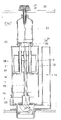
- La figure 1 est une vue en coupe axiale d'un premier mode d'exécution du mécanisme de chasse selon l'invention, montré installé dans un réservoir de chasse d'eau dont on a seulement et partiellement représenté le fond et le couvercle, ledit mécanisme se trouvant en position de repos.
- La figure 2 est une vue analogue à la figure 1 et représente le bouton-poussoir après son enfoncement ayant entraîné la montée de l'équipage mobile et l'ouverture de l'orifice de vidange.
- La figure 3 est une vue quasi identique à la figure 2 et montrant la position du dispositif de commande, après relâchement du bouton-poussoir, durant la vidange.
- La figure 4 est une vue analogue aux précédentes et montrant l'interruption volontaire de l'écoulement de l'eau, au cours du processus de vidange du réservoir, par enfoncement du bouton-poussoir.
- La figure 5 est une vue en coupe transversale et à plus grande échelle, suivant la ligne 5-5 de la figure 4.
- La figure 6 est une vue en coupe transversale et à plus grande échelle, selon la ligne 6-6 de la figure 4.
- La figure 7 est une vue en coupe axiale d'un deuxième mode d'exécution du mécanisme de chasse selon l'invention, représenté en position de repos.
- Figure 1 is an axial sectional view of a first embodiment of the flushing mechanism according to the invention, shown installed in a flushing tank of which only the bottom and the cover have been shown, said mechanism in the rest position.
- Figure 2 is a view similar to Figure 1 and shows the push button after it is pressed having caused the moving equipment to rise and the drain opening to open.
- Figure 3 is a view almost identical to Figure 2 and showing the position of the control device, after releasing the push button, during emptying.
- Figure 4 is a view similar to the previous ones and showing the voluntary interruption of the flow of water, during the emptying process of the tank, by pressing the push button.
- FIG. 5 is a view in cross section and on a larger scale, along line 5-5 of FIG. 4.
- FIG. 6 is a view in cross section and on a larger scale, along line 6-6 of FIG. 4.
- Figure 7 is an axial sectional view of a second embodiment of the flushing mechanism according to the invention, shown in the rest position.
On se réfère auxdits dessins pour décrire deux exemples de réalisation intéressants, quoique non limitatifs, du mécanisme de chasse interrompable, à écoulement minimal assuré,suivant l'invention.Reference is made to said drawings to describe two interesting, although not limiting, embodiments of the interruptible flushing mechanism, with minimum guaranteed flow, according to the invention.
Selon le mode d'exécution illustré aux figures 1 à 6, ce mécanisme comprend notamment :
- une enveloppe extérieure 1 de forme générale cylindrique ;
- un
flotteur 2 logé avec une aptitude de déplacement vertical dans ladite enveloppe et solidaire, en translation axiale, duclapet 3 d'obturation de l'orifice de vidange du réservoir ; - un tube de
surverse 4 comportant un orifice supérieur A et un orifice inférieur B, de manière à permettre une décharge automatique d'un éventuel trop plein qui pourrait résulter de la fermeture défectueuse du robinet commandant l'admission d'eau dans le réservoir ; - un système de commande à bouton-poussoir permettant le soulèvement du clapet ;
- un culot désigné, dans son ensemble, par la
référence 5, et destiné à être installé fixement dans l'orifice 6 que présente lefond 7 du réservoir (partiellement représenté aux figures 1 à 4).
- an
outer casing 1 of generally cylindrical shape; - a
float 2 housed with an aptitude for vertical movement in said envelope and integral, in axial translation, with thevalve 3 for closing the tank emptying orifice; - an
overflow tube 4 comprising an upper orifice A and a lower orifice B, so as to allow automatic discharge of any overflow which could result from the defective closing of the valve controlling the admission of water into the tank; - a push button control system allowing the valve to be raised;
- a base designated, as a whole, by the
reference 5, and intended to be fixedly installed in theorifice 6 presented by thebottom 7 of the tank (partially shown in Figures 1 to 4).
Le culot 5 comporte un orifice central C dont le bord circulaire supérieur 8 constitue le siège du clapet 3.The
Lorsque le mécanisme de chasse est positionné à l'intérieur d'un réservoir de chasse lui-même fixé sur une cuvette de cabinet d'aisances, le culot 5 est installé fixement, au moyen d'un écrou (non représenté) se vissant sur la portion cylindrique inférieure filetée 5a dudit culot, dans l'orifice 6.When the flushing mechanism is positioned inside a flushing tank itself fixed on a toilet bowl, the
De la sorte, l'orifice central C du culot 5 constitue l'orifice de vidange dudit réservoir. L'étanchéité entre le fond 7 du réservoir et l'assise ou face d'appui du culot 5, est réalisée au moyen d'un joint annulaire intermédiaire 9 exécuté en caoutchouc ou autre matériau adéquat.In this way, the central orifice C of the
La base de l'enveloppe extérieure 1 et le culot 5 sont agencés de manière complémentaire ou pourvus de moyens de jonction complémentaires permettant de les assembler rigidement, de façon séparable, tout en autorisant le passage de l'eau entre ladite base et ledit culot. Le culot 5 est, par exemple, pourvu de trois fourchettes de verrouillage 10 espacées de 120 degrés et entre les branches desquelles peut être engagée et retenue la base de l'enveloppe 1. Entre les fourchettes de verrouillage se trouvent ainsi ménagées de larges ouvertures 11, pour le passage de l'eau.The base of the
Selon l'invention, la partie supérieure de l'enveloppe 1, est agencée de façon à constituer un réservoir auxiliaire 12.According to the invention, the upper part of the
La partie supérieure 1a de l'enveloppe 1 constitue la paroi latérale de ce réservoir dont le fond est formé, selon le mode d'exécution illustré aux figures 1 à 4, par une paroi ou cloison circulaire 13. Au voisinage du fond 13, la paroi latérale 1a du réservoir 12 est pourvue d'orifices d'évacuation 14 répartis sur la périphérie de ladite paroi, ces orifices étant placés au-dessus dudit fond selon le mode d'exécution illustré aux figures 1 à 6.The upper part 1a of the
Les orifices 14 sont disposés approximativement dans la partie médiane de la hauteur de l'enveloppe 1 et du mécanisme de chasse, et à un niveau se situant très nettement au-dessous du niveau où se trouve placé l'orifice supérieur à du tube de surverse 4, par exemple environ à mi-hauteur de ce dernier.The
Le flotteur 2 du mécanisme de chasse est logé à l'intérieur de la chambre de sustentation 12. Ce flotteur est avantageusement constitué par une cloche ouverte à sa base et fermée à son sommet et cette cloche est rigidement solidaire d'un tube-entretoise 15 par l'intermédiaire duquel elle est reliée au clapet 3. Ce dernier est, par exemple, constitué par un joint d'étanchéité en forme de couronne circulaire, réalisé en caoutchouc ou autre matériau analogue, et il est installé dans une gorge périphérique que présente une monture rigide 16 constituant l'extrémité inférieure du tube-entretoise 15.The
De manière très intéressante, le système de commande à bouton-poussoir est du genre décrit et illustré dans le document FR-A-2.591.250. Ce système de commande permettant le soulèvement du clapet 3, comprend :
- un bouton-
poussoir 17, mobile axialement et verticalement, ce bouton-poussoir étant logé dans unecoupelle 18 appelée à être installée fixement dans letrou 19 que présente lecouvercle 20 des réservoirs de chasse pour le passage de la tige des dispositifs de commande ; cettecoupelle 18 est, par exemple, solidaire d'une tige tubulaire 18a dotée d'un filetage extérieur par l'intermédiaire duquel elle est vissée dans l'écrou 32 constitué par le chapeau 1b formant le sommet de l'enveloppe extérieure 1 ; - un
ressort 21 agissant en compression et tendant à repousser le bouton-poussoir 17, vers l'extérieur, c'est-à-dire vers le haut ; ce ressort étant par exemple calé, par l'intermédiaire de ses extrémités opposées, d'une part, contre la face inférieure dudit bouton-poussoir et, d'autre part, contre le fond de lacoupelle 18 ; - une tige axiale de
transmission 22 solidaire en translation axiale du bouton-poussoir 17 et qui peut être reliée à celui-ci par l'intermédiaire de son extrémité supérieure ; cette tige de transmission traversant longitudinalement l'équipage mobile 2-15-3 ; - et un organe de
soulèvement 23 monté avec une aptitude de pivotement à l'extrémité inférieure de la tige detransmission 22 et disposé au-dessous duclapet 3 ; cet organe est, par exemple, constitué par une came ou par un petit levier du premier type dont l'axe d'oscillation est porté par unetraverse 24 disposée fixement à travers l'orifice d'évacuation duculot 5, au-dessous du siège du clapet.
- a
push button 17, axially and vertically movable, this push button being housed in acup 18 which is to be fixedly installed in thehole 19 presented by thecover 20 of the flush tanks for the passage of the rod of the ordered ; thiscup 18 is, for example, integral with a tubular rod 18a provided with an external thread by means of which it is screwed into thenut 32 constituted by the cap 1b forming the top of theexternal envelope 1; - a
spring 21 acting in compression and tending to push thepush button 17 outward, that is to say upward; this spring being for example wedged, by means of its opposite ends, on the one hand, against the underside of said push button and, on the other hand, against the bottom of thecup 18; - an
axial transmission rod 22 secured in axial translation to the push-button 17 and which can be connected to the latter via its upper end; this transmission rod passing longitudinally through the moving assembly 2-15-3; - and a
lifting member 23 mounted with a pivotability at the lower end of thetransmission rod 22 and arranged below thevalve 3; this member is, for example, constituted by a cam or by a small lever of the first type, the oscillation axis of which is carried by across-member 24 fixedly disposed through the evacuation orifice of thebase 5, below the valve seat.
Le mécanisme selon l'invention comprend encore des moyens permettant une vidange rapide de la chambre de sustentation 12. Selon le mode d'exécution illustré aux figures 1 à 6, ces moyens comprennent, outre les orifices 14 précédemment décrits, un obturateur constitué par la paroi latérale cylindrique 26 d'un réservoir auxiliaire 25 de forme annulaire, disposé, avec une aptitude de déplacement axial, autour du tube-entretoise 15. Ce réservoir auxiliaire 25 est ouvert à sa partie supérieure et, sa paroi latérale 26 comporte, à proximité du fond 25a dudit réservoir des orifices 27 dont la forme, le nombre et la répartition correspondent à la forme, au nombre et à la répartition des orifices 14, en regard desquels ils peuvent être placés. La paroi latérale 2a du flotteur 2 est logée dans le réservoir auxiliaire annulaire 25, la hauteur de cette paroi étant sensiblement égale à la hauteur de la paroi cylindrique interne 25b dudit réservoir. D'autre part, la paroi latérale externe 26 du réservoir auxilaire annulaire 25 a une hauteur sensiblement plus importante que celle de la paroi interne 25b dudit réservoir.The mechanism according to the invention further comprises means allowing rapid emptying of the
Lorsque la paroi 1a se trouve placée devant les orifices 27, ces derniers se trouvent obturés, de manière non rigoureusement étanche, par ladite paroi.When the wall 1a is placed in front of the
Le tube-entretoise 15 comporte un prolongement tubulaire 15a dont l'orifice supérieur D se trouve placé sensiblement au niveau où se trouve l'orifice A du tube de surverse 4, lorsque le dispositif est au repos, et, de préférence, un peu au-dessous de ce niveau.The
La paroi latérale 26 du réservoir auxiliaire 25 est rigidement solidaire de deux colonnettes ou tiges de liaison 28 orientées vers le haut et diamétralement opposées. Une barrette horizontale d'entraînement 29, disposée perpendiculairement aux tiges 28, relie rigidement la partie supérieure de ces dernières. Des ressorts 30 agissant en compression sont disposés autour de la partie supérieure des tiges 28. Ces ressorts sont calés, d'une part, contre la face inférieure de la barrette 29 et, d'autre part, contre un épaulement circulaire 1c de l'enveloppe extérieure 1.The
On conçoit que les ressorts 30 tendent à repousser la barrette d'entraînement 29 vers le haut et à maintenir, par conséquent, l'obturateur 26 et le réservoir auxiliaire 25 en position haute.It will be appreciated that the
La tige de transmission 22 est munie d'un organe de poussée permettant d'abaisser l'ensemble : obturateur 26-réservoir auxiliaire 25, lorsqu'on appuie sur le bouton-poussoir 17. Cet organe de poussée est, par exemple, constitué par une bague 31 calée sur la tige 22 et disposée au-dessus de la barrette 29, et, de préférence, en contact avec cette dernière.The
Le tube de surverse 4 du mécanisme de chasse est disposé à l'extérieur de l'enveloppe 1. Son orifice inférieur B est relié au culot 5 par un conduit 32 débouchant dans ledit culot, au-dessous du siège 8 du clapet 3.The
On décrit ci-après le fonctionnement de ce mode d'exécution du mécanisme de chasse selon l'invention.The operation of this embodiment of the flushing mechanism according to the invention is described below.
En période de remplissage ou d'inactivité (figure 1), l'équipage mobile 2-15-3 est en position basse, le clapet 3 repose sur son siège 8 et obture l'orifice de vidange C. D'autre part, le bouton-poussoir 17 et la bague de poussée 31 sont en position haute, ainsi que l'obturateur 26 et le réservoir auxiliaire 25 ; dans cette position, les orifices 27 du réservoir auxiliaire 25 sont placés au-dessus du niveau où se trouvent les orifices 14 de la paroi 1a et sont donc obturés par cette dernière. En fin de remplissage, le niveau N de l'eau contenue dans le réservoir se situe généralement un peu au-dessous de l'emplacement où se trouvent les extrémités supérieures du tube de surverse 4 et du prolongement tubulaire 15a du tube-entretoise 15, de sorte que ledit tube de surverse peut remplir sa fonction en cas de fermeture défectueuse du robinet d'alimentation. L'eau remplit également la chambre de sustentation 12 et le réservoir auxiliaire 25, logé dans cette dernière.During the filling or inactivity period (Figure 1), the moving part 2-15-3 is in the low position, the
En appuyant sur le bouton-poussoir 17, on provoque la descente de la tige de transmission 22 et le basculement du levier 23 assurant le soulèvement du clapet 3 et de l'équipage mobile 2-15-3. L'eau afflue vers l'orifice de vidange C, à travers les ouvertures 11 ménagées entre la base de l'enveloppe 1 et la surface supérieure du culot 5, et le flotteur 2 communique un mouvement de remontée supplémentaire à l'équipage mobile 2-15-3 (figure 2) dont le déplacement ascendant se trouve arrêté par un épaulement interne 1d de l'enveloppe 1 contre lequel vient buter le sommet du flotteur 2. On observe que la descente de la tige 22 a également provoqué, par l'action de la bague de poussée 31, la descente du réservoir auxiliaire 25 et de l'obturateur 26 dont les orifices 27 sont venus se placer en regard des orifices 14 de la paroi latérale 1a. Ceci n'a cependant aucune conséquence en raison du fait qu'il y a de l'eau à la fois à l'intérieur et à l'extérieur de l'enveloppe 1.By pressing the
Lorsqu'on relâche le bouton-poussoir 17, celui-ci remonte sous l'action du ressort 21, en entraînant un mouvement ascendant correspondant de la tige de transmission 22 et de la bague de poussée 31, tandis que le levier basculant 23 reprend sa position initiale (figure 3). Simultanément, l'obturateur 26 et le réservoir auxiliaire 25 remontent sous l'action des ressorts 30.When the
Lors d'une vidange totale du réservoir, l'équipage mobile 2-15-3 reste en position soulevée tant que la flottabilité du flotteur reste assurée. Le niveau de l'eau contenue dans le réservoir de chasse descend progressivement et rapidement, tandis que le niveau de l'eau contenue dans la chambre de sustentation 12 et plus précisément dans le réservoir auxiliaire 25 descend également mais beaucoup plus lentement en raison du fait que les orifices 27 ménagés à proximité du fond de ce dernier sont obturés de façon non étanche par la paroi cylindrique obturatrice 26. L'équipage mobile 2-15-3 retombe naturellement dans sa position de repos et d'obturation de l'orifice de vidange C (figure 1) lorsqu'il n'y a plus d'eau dans le réservoir auxiliaire 25 et que la sustentation du flotteur 2 n'est plus assurée.During a complete emptying of the tank, the moving part 2-15-3 remains in the raised position as long as the buoyancy of the float remains ensured. The level of the water contained in the flushing tank decreases gradually and rapidly, while the level of the water contained in the
Il est possible d'interrompre la vidange, mais pas avant que le niveau descendant de l'eau contenue dans le réservoir de chasse n'ait atteint les orifices 14, c'est-à-dire pas avant qu'un certain volume d'eau n'ait été évacué.It is possible to interrupt the emptying, but not before the falling level of the water contained in the flushing tank has reached the
En effet, si l'on appuie sur le bouton-poussoir 17 alors que le niveau N' de l'eau contenue dans le réservoir de chasse se situe au-dessus des orifices 14, la descente de l'ensemble obturateur 26-réservoir auxiliaire 25 et la mise en correspondance des orifices 14 et 27 ne permettront pas une évacuation rapide de l'eau contenue dans ledit réservoir auxiliaire, pour la raison précédemment exprimée, la sustentation du flotteur 2 restant assurée.Indeed, if the push-
Par contre, si l'on appuie sur le bouton-poussoir 17 alors que le niveau descendant N'' de l'eau contenue dans le réservoir de chasse, a atteint ou dépassé les orifices 14, la mise en correspondance desdits orifices 14 et des orifices 27, permet l'évacuation rapide du réservoir auxiliaire et la descente de l'équipage mobile 2-15-3 (figure 4), la vidange étant interrompue dès que l'on relâche ledit bouton-poussoir permettant la retombée du clapet 3 sur son siège 8.On the other hand, if the push-
Le mode de réalisation du mécanisme de chasse illustré à la figure 7 diffère de celui précédemment décrit, principalement par le fait que la chambre de sustentation 12 ne renferme pas un réservoir auxiliaire et que l'obturateur 26 permettant de placer ou non les orifices 14 ménagés dans la paroi latérale de l'enveloppe 1, en relation avec ladite chambre, est constitué par le fond mobile de cette dernière.The embodiment of the flushing mechanism illustrated in Figure 7 differs from that previously described, mainly by the fact that the
Selon ce mode d'exécution, l'obturateur mobile 26 est constitué par une plaque circulaire disposée autour du tube-entretoise 15 et apte à glisser, de manière non étanche, le long de ce dernier et de la surface interne de l'enveloppe 1. Cette plaque 26 constituant le fond mobile de la chambre de sustentation 12, est reliée, par l'intermédiaire de deux tiges ou colonnettes verticales et parallèles 28, à une barrette d'entraînement 29. Des ressorts 30 tendent à maintenir l'ensemble 26-28-29 en position haute, de la manière indiquée précédemment.According to this embodiment, the
Le mécanisme de chasse réalisé selon ce mode d'exécution permet également d'interrompre le processus de vidange en appuyant une deuxième fois sur le bouton-poussoir 17, mais cette interruption ne peut avoir lieu tant que le niveau descendant de l'eau n'a pas atteint les orifices 14.The flushing mechanism produced according to this embodiment also makes it possible to interrupt the emptying process by pressing the push button 17 a second time, but this interruption cannot take place as long as the falling level of the water does not has not reached holes 14.
Claims (10)
Priority Applications (2)
| Application Number | Priority Date | Filing Date | Title |
|---|---|---|---|
| AT91430017T ATE130651T1 (en) | 1991-06-25 | 1991-06-25 | INTERRUPTABLE FLUSHING MECHANISM WITH SECURED MINIMUM RINSE. |
| DE69114836T DE69114836D1 (en) | 1991-06-25 | 1991-06-25 | Interruptible flushing mechanism with secured minimal flushing. |
Applications Claiming Priority (3)
| Application Number | Priority Date | Filing Date | Title |
|---|---|---|---|
| FR9006414A FR2662194B1 (en) | 1990-05-17 | 1990-05-17 | INTERRUPTABLE HUNTING MECHANISM, WITH MINIMUM ASSURED FLOW. |
| AU81232/91A AU641259B2 (en) | 1990-05-17 | 1991-07-23 | Stoppable flushing mechanism with assured minimal flow |
| US08/111,432 US5305474A (en) | 1990-05-17 | 1993-08-25 | Stoppable flushing mechanism with assured minimal flow |
Publications (2)
| Publication Number | Publication Date |
|---|---|
| EP0520114A1 true EP0520114A1 (en) | 1992-12-30 |
| EP0520114B1 EP0520114B1 (en) | 1995-11-22 |
Family
ID=27156420
Family Applications (1)
| Application Number | Title | Priority Date | Filing Date |
|---|---|---|---|
| EP91430017A Expired - Lifetime EP0520114B1 (en) | 1990-05-17 | 1991-06-25 | Interruptable flushing mechanism with garanteed minimum flush |
Country Status (4)
| Country | Link |
|---|---|
| US (1) | US5305474A (en) |
| EP (1) | EP0520114B1 (en) |
| AU (1) | AU641259B2 (en) |
| FR (1) | FR2662194B1 (en) |
Cited By (2)
| Publication number | Priority date | Publication date | Assignee | Title |
|---|---|---|---|---|
| ES2073985A2 (en) * | 1993-02-24 | 1995-08-16 | Martinez Juan Vidal | System for metering water for lavatory cisterns |
| ES2137810A1 (en) * | 1993-12-17 | 1999-12-16 | Idrols Sa | Discharger for cisterns with discharge interruption |
Families Citing this family (17)
| Publication number | Priority date | Publication date | Assignee | Title |
|---|---|---|---|---|
| DE4122394A1 (en) * | 1991-07-05 | 1993-01-07 | Heinrich Menge | RINSING DEVICE |
| FR2680192B1 (en) | 1991-08-09 | 1993-10-15 | Matieres Plastiques Ste Phoceenn | DUAL-CONTROLLED HUNTING MECHANISM FOR SELECTIVELY COMPLETE OR PARTIAL DRAINING OF THE TANK. |
| DE9311189U1 (en) * | 1992-09-21 | 1993-09-09 | Geberit Ag | Drain valve for a cistern |
| DE29503497U1 (en) * | 1994-05-16 | 1995-04-20 | Geberit Technik Ag | Flushing device for a water closet |
| DE29517363U1 (en) * | 1995-01-16 | 1995-12-21 | Geberit Technik Ag | Flushing device in a toilet cistern |
| US5956781A (en) * | 1996-02-20 | 1999-09-28 | James Hardie Research Pty Limited | Dual flush cistern |
| DE29702564U1 (en) * | 1997-02-14 | 1997-04-03 | Schneider Helmhold Dr | Drainage device on a toilet cistern with either full or partial flushing |
| DE19748621A1 (en) * | 1997-11-04 | 1999-05-06 | Dal Georg Rost & Soehne Sanita | Drain valve for cisterns |
| SE515154C2 (en) * | 1998-08-26 | 2001-06-18 | Ninotech Hb | Method and device for time-controlled flushing in flushing toilets |
| US6081938A (en) * | 1998-09-14 | 2000-07-04 | Fluidmaster, Inc. | Dual-flush valve |
| US7634821B2 (en) * | 2005-11-07 | 2009-12-22 | Kohler Co. | Canister flush valve |
| EP1870527B1 (en) * | 2006-06-20 | 2017-05-31 | Geberit International AG | Device for activating the outlet valve of a sanitary article. |
| DE102006051823A1 (en) * | 2006-11-03 | 2008-05-08 | Tece Gmbh | Dual flush discharge valve |
| ATE483073T1 (en) * | 2007-05-25 | 2010-10-15 | Geberit Int Ag | ACTUATING DEVICE FOR A SPOUT SET AND SPOUT SET WITH SUCH ACTUATING DEVICE AND METHOD FOR MOUNTING SUCH A SPOUT SET |
| US8806669B2 (en) * | 2008-04-10 | 2014-08-19 | Kohler Co. | Toilet flush valve with reducing cross section valve seat |
| ES2605422T3 (en) * | 2012-08-03 | 2017-03-14 | Geberit International Ag | Height adjustable discharge taps |
| EP2865817B1 (en) * | 2013-10-28 | 2016-03-02 | Geberit International AG | Outlet fitting for a toilet cistern |
Citations (4)
| Publication number | Priority date | Publication date | Assignee | Title |
|---|---|---|---|---|
| DE639760C (en) * | 1935-04-12 | 1936-12-12 | Albert Gebert Jun | Waste cistern with valve lock |
| FR1455293A (en) * | 1965-08-11 | 1966-04-01 | W J Stokvis Konink Fabriek Van | Cistern with bottom valve |
| FR2591250A1 (en) * | 1985-03-19 | 1987-06-12 | Spmp Sa | Flushing device controlled by push-button for water flushing tank |
| FR2621630A1 (en) * | 1987-10-09 | 1989-04-14 | Pocachard Thierry | WATER FLUSHING CONTROL MECHANISM FOR TOILET BY PUSH BUTTON |
Family Cites Families (5)
| Publication number | Priority date | Publication date | Assignee | Title |
|---|---|---|---|---|
| AU1238870A (en) * | 1970-03-10 | 1971-09-16 | Better Packages, Inc | Pressure sensitive adhesive tape dispenser |
| US3987752A (en) * | 1975-05-05 | 1976-10-26 | Owens-Corning Fiberglas Corporation | Apparatus for dispensing elongate flexible material |
| CH643622A5 (en) * | 1979-12-18 | 1984-06-15 | Geberit Ag | Drain set for cistern. |
| ATE17142T1 (en) * | 1982-09-15 | 1986-01-15 | Rost & Soehne Georg | WATER TANK DRAIN VALVE. |
| FR2621378B1 (en) * | 1987-10-05 | 1989-12-15 | Siamp Cedap Reunies | ROCKER OPERATION DEVICE FOR THE DRAIN VALVE OF A HUNTING TANK |
-
1990
- 1990-05-17 FR FR9006414A patent/FR2662194B1/en not_active Expired - Lifetime
-
1991
- 1991-06-25 EP EP91430017A patent/EP0520114B1/en not_active Expired - Lifetime
- 1991-07-23 AU AU81232/91A patent/AU641259B2/en not_active Ceased
-
1993
- 1993-08-25 US US08/111,432 patent/US5305474A/en not_active Expired - Fee Related
Patent Citations (4)
| Publication number | Priority date | Publication date | Assignee | Title |
|---|---|---|---|---|
| DE639760C (en) * | 1935-04-12 | 1936-12-12 | Albert Gebert Jun | Waste cistern with valve lock |
| FR1455293A (en) * | 1965-08-11 | 1966-04-01 | W J Stokvis Konink Fabriek Van | Cistern with bottom valve |
| FR2591250A1 (en) * | 1985-03-19 | 1987-06-12 | Spmp Sa | Flushing device controlled by push-button for water flushing tank |
| FR2621630A1 (en) * | 1987-10-09 | 1989-04-14 | Pocachard Thierry | WATER FLUSHING CONTROL MECHANISM FOR TOILET BY PUSH BUTTON |
Cited By (2)
| Publication number | Priority date | Publication date | Assignee | Title |
|---|---|---|---|---|
| ES2073985A2 (en) * | 1993-02-24 | 1995-08-16 | Martinez Juan Vidal | System for metering water for lavatory cisterns |
| ES2137810A1 (en) * | 1993-12-17 | 1999-12-16 | Idrols Sa | Discharger for cisterns with discharge interruption |
Also Published As
| Publication number | Publication date |
|---|---|
| FR2662194B1 (en) | 1992-08-07 |
| AU8123291A (en) | 1993-01-28 |
| AU641259B2 (en) | 1993-09-16 |
| US5305474A (en) | 1994-04-26 |
| EP0520114B1 (en) | 1995-11-22 |
| FR2662194A1 (en) | 1991-11-22 |
Similar Documents
| Publication | Publication Date | Title |
|---|---|---|
| EP0520114B1 (en) | Interruptable flushing mechanism with garanteed minimum flush | |
| EP0528740B1 (en) | Dual control flushing mechanism, selectively emptying the cistern partially or completely | |
| WO2002059431A1 (en) | Flushing mechanism for toilet tank | |
| EP0522218B1 (en) | Push-button flushing mechanism with submersible float | |
| FR2676480A1 (en) | Removal device for cistern, with variable discharge | |
| EP0311542B1 (en) | Mechanism for activating the flushing of a toilet by a push button | |
| FR2658219A1 (en) | Flush mechanism with push-button control and with controllable action | |
| EP0685605A1 (en) | Toilet flushing device with double actuation button allowing the delivery of a predetermined flush quantity | |
| FR2698645A1 (en) | Interruptable toilet flush mechanism - has tilting cams which move along slots to raise moving part and push stopper valve away from seating | |
| FR2660679A1 (en) | Control device with push-button and tilting cam for flushing mechanism | |
| FR2678300A1 (en) | Water flush with two filling levels | |
| EP0553577B1 (en) | Toilet flushing control device with regulatable water volume necessary to clean the bowl properly | |
| WO1997017503A1 (en) | Dual cistern flush control device | |
| EP0124458A1 (en) | Flushing device for a flushing tank operated by a push button | |
| EP1084764A1 (en) | Dispensing device for a container | |
| FR2591250A1 (en) | Flushing device controlled by push-button for water flushing tank | |
| CA2046133A1 (en) | Interrumptible, minimal flow garanteed flushing mechanism | |
| FR2612535A1 (en) | Emptying device for a water-flushing tank | |
| EP0209477B1 (en) | Flushing device having a floating siphon bell for flushing tanks | |
| FR2712320A1 (en) | Variable capacity WC flushing system | |
| FR2576620A1 (en) | Water flushing device, particularly for a W.C. bowl | |
| FR2707316A1 (en) | Sanitary appliance water flushing device with two predetermined flush volumes | |
| FR2494464A1 (en) | Auxiliary float chamber for toilet system for faster refilling - uses auxiliary float chamber which cannot fill until main cistern is full, thus holding inlet valve fully open, giving faster filling | |
| FR2715178A1 (en) | Two-position cistern flushing mechanism for toilet etc. | |
| FR2684705A1 (en) | Flush device |
Legal Events
| Date | Code | Title | Description |
|---|---|---|---|
| PUAI | Public reference made under article 153(3) epc to a published international application that has entered the european phase |
Free format text: ORIGINAL CODE: 0009012 |
|
| AK | Designated contracting states |
Kind code of ref document: A1 Designated state(s): AT BE CH DE DK ES GB GR IT LI LU NL SE |
|
| 17P | Request for examination filed |
Effective date: 19930624 |
|
| 17Q | First examination report despatched |
Effective date: 19941221 |
|
| GRAA | (expected) grant |
Free format text: ORIGINAL CODE: 0009210 |
|
| AK | Designated contracting states |
Kind code of ref document: B1 Designated state(s): AT BE CH DE DK ES GB GR IT LI LU NL SE |
|
| PG25 | Lapsed in a contracting state [announced via postgrant information from national office to epo] |
Ref country code: IT Free format text: LAPSE BECAUSE OF FAILURE TO SUBMIT A TRANSLATION OF THE DESCRIPTION OR TO PAY THE FEE WITHIN THE PRESCRIBED TIME-LIMIT;WARNING: LAPSES OF ITALIAN PATENTS WITH EFFECTIVE DATE BEFORE 2007 MAY HAVE OCCURRED AT ANY TIME BEFORE 2007. THE CORRECT EFFECTIVE DATE MAY BE DIFFERENT FROM THE ONE RECORDED. Effective date: 19951122 Ref country code: GB Effective date: 19951122 Ref country code: DK Effective date: 19951122 Ref country code: NL Free format text: LAPSE BECAUSE OF FAILURE TO SUBMIT A TRANSLATION OF THE DESCRIPTION OR TO PAY THE FEE WITHIN THE PRESCRIBED TIME-LIMIT Effective date: 19951122 Ref country code: ES Free format text: THE PATENT HAS BEEN ANNULLED BY A DECISION OF A NATIONAL AUTHORITY Effective date: 19951122 Ref country code: AT Effective date: 19951122 Ref country code: GR Free format text: LAPSE BECAUSE OF FAILURE TO SUBMIT A TRANSLATION OF THE DESCRIPTION OR TO PAY THE FEE WITHIN THE PRESCRIBED TIME-LIMIT Effective date: 19951122 |
|
| REF | Corresponds to: |
Ref document number: 130651 Country of ref document: AT Date of ref document: 19951215 Kind code of ref document: T |
|
| REF | Corresponds to: |
Ref document number: 69114836 Country of ref document: DE Date of ref document: 19960104 |
|
| PG25 | Lapsed in a contracting state [announced via postgrant information from national office to epo] |
Ref country code: SE Effective date: 19960222 |
|
| PG25 | Lapsed in a contracting state [announced via postgrant information from national office to epo] |
Ref country code: DE Effective date: 19960223 |
|
| NLV1 | Nl: lapsed or annulled due to failure to fulfill the requirements of art. 29p and 29m of the patents act | ||
| GBV | Gb: ep patent (uk) treated as always having been void in accordance with gb section 77(7)/1977 [no translation filed] |
Effective date: 19951122 |
|
| PG25 | Lapsed in a contracting state [announced via postgrant information from national office to epo] |
Ref country code: LI Effective date: 19960630 Ref country code: LU Free format text: LAPSE BECAUSE OF NON-PAYMENT OF DUE FEES Effective date: 19960630 Ref country code: BE Effective date: 19960630 Ref country code: CH Effective date: 19960630 |
|
| PLBE | No opposition filed within time limit |
Free format text: ORIGINAL CODE: 0009261 |
|
| STAA | Information on the status of an ep patent application or granted ep patent |
Free format text: STATUS: NO OPPOSITION FILED WITHIN TIME LIMIT |
|
| 26N | No opposition filed | ||
| BERE | Be: lapsed |
Owner name: SOC. PHOCEENNE DE MATIERES PLASTIQUES SPMPS.A. Effective date: 19960630 |
|
| REG | Reference to a national code |
Ref country code: CH Ref legal event code: PL |