EP0519330A1 - Condensateur à électrolyte solide du type puce avec fusible - Google Patents
Condensateur à électrolyte solide du type puce avec fusible Download PDFInfo
- Publication number
- EP0519330A1 EP0519330A1 EP92109842A EP92109842A EP0519330A1 EP 0519330 A1 EP0519330 A1 EP 0519330A1 EP 92109842 A EP92109842 A EP 92109842A EP 92109842 A EP92109842 A EP 92109842A EP 0519330 A1 EP0519330 A1 EP 0519330A1
- Authority
- EP
- European Patent Office
- Prior art keywords
- fuse
- solid electrolytic
- electrolytic capacitor
- chip
- resin
- Prior art date
- Legal status (The legal status is an assumption and is not a legal conclusion. Google has not performed a legal analysis and makes no representation as to the accuracy of the status listed.)
- Granted
Links
Images


Classifications
-
- H—ELECTRICITY
- H01—ELECTRIC ELEMENTS
- H01H—ELECTRIC SWITCHES; RELAYS; SELECTORS; EMERGENCY PROTECTIVE DEVICES
- H01H85/00—Protective devices in which the current flows through a part of fusible material and this current is interrupted by displacement of the fusible material when this current becomes excessive
- H01H85/02—Details
- H01H85/04—Fuses, i.e. expendable parts of the protective device, e.g. cartridges
- H01H85/041—Fuses, i.e. expendable parts of the protective device, e.g. cartridges characterised by the type
- H01H85/0411—Miniature fuses
-
- H—ELECTRICITY
- H01—ELECTRIC ELEMENTS
- H01G—CAPACITORS; CAPACITORS, RECTIFIERS, DETECTORS, SWITCHING DEVICES OR LIGHT-SENSITIVE DEVICES, OF THE ELECTROLYTIC TYPE
- H01G9/00—Electrolytic capacitors, rectifiers, detectors, switching devices, light-sensitive or temperature-sensitive devices; Processes of their manufacture
- H01G9/0003—Protection against electric or thermal overload; cooling arrangements; means for avoiding the formation of cathode films
-
- H—ELECTRICITY
- H01—ELECTRIC ELEMENTS
- H01H—ELECTRIC SWITCHES; RELAYS; SELECTORS; EMERGENCY PROTECTIVE DEVICES
- H01H85/00—Protective devices in which the current flows through a part of fusible material and this current is interrupted by displacement of the fusible material when this current becomes excessive
- H01H85/02—Details
- H01H85/04—Fuses, i.e. expendable parts of the protective device, e.g. cartridges
- H01H85/041—Fuses, i.e. expendable parts of the protective device, e.g. cartridges characterised by the type
- H01H85/0411—Miniature fuses
- H01H2085/0414—Surface mounted fuses
Definitions
- the present invention relates to a chip-type solid electrolytic capacitor with a fuse and, more particularly, to a structure of a cathode terminal section with a fuse.
- a solid electrolytic capacitor is used in various electronic circuits, and is advantageous in that its failure rate is low. Once failure occurs, however, there will be many cases where short-circuiting occurs. When large short-circuiting current flows in such a case, a capacitor element may be heated up to be burnt out.
- a solid electrolytic capacitor of the type in which a fuse is built in has generally been used.
- This solid electrolytic capacitor will hereinafter be referred to as "a solid electrolytic capacitor with a fuse”.
- Figs. 4(a) and 4(b) are a perspective view and a cross-sectional view, respectively, showing the constitution of a conventional solid electrolytic capacitor with a fuse.
- a capacitor element 1 is composed of an anode lead 2 and a cathode layer 3.
- An anode terminal 4 is connected to the anode lead 2.
- the cathode layer 3 and a cathode terminal 5 are adhered to each other by an insulating adhesive 6.
- a fuse 7 is connected to the cathode layer 3 and the cathode terminal 5 by solder 8 so that the cathode layer 3 and the cathode terminal 5 are bridged to each other.
- the fuse 7 is covered with an elastic resin 9, and all of the elements referred to the above are armored by a molding resin 10.
- the conventional chip-type solid electrolytic capacitor with a fuse as described above, is of the constitution in which the cathode layer and the cathode terminal are electrically connected to each other by the fuse. With this arrangement, therefore, the conventional solid electrolytic capacitor with a fuse has the following disadvantages:
- the manufacturing step, particularly, the fuse connecting step will be troublesome and cumbersome.
- a chip-type solid electrolytic capacitor with a fuse comprising: a solid electrolytic capacitor element; an anode terminal connected to an anode lead led from the solid electrolytic capacitor element; a cathode terminal with a fuse, connected to a cathode layer of the solid electrolytic capacitor element; and a molding resin with which all of the elements are covered so that predetermined portions of the respective anode terminal and cathode terminal are exposed, wherein the cathode terminal has an inside connecting portion, an outside lead portion, and protective resin protecting the fuse for bridging between the inside connecting portion and the outside lead portion, characterized in that part of the protective resin is exposed from the molding resin.
- the cathode terminal has the inside connecting portion, the outside lead portion, and the fuse for bridging between the inside connecting portion and the outside lead portion, and the predetermined portions including a fuse connecting portion are protectively insulated in advance by the protective resin.
- the inside connecting portion of the cathode terminal formed beforehand and the cathode layer of the capacitor element are assembled together so as to be adhered and conducted to each other.
- the connecting length of the fuse is made constant, the step of bridging between the inside connecting portion and the outside lead portion of the cathode terminal by the fuse is automated and simplified to increase the yield.
- the manufacturing cost can be reduced and the reliability of the fuse connection can be improved.
- the chap-type solid electrolytic capacitor with a fuse which is stable in fuse melting properties, to be used in a wide variety of articles can be provided.
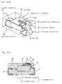
- Fig. 1 is a partially cross-sectional perspective view showing the inside structure of an embodiment according to the invention
- Figs. 2(a) and 2(b) are a cross-sectional view of Fig. 1 and a top plan view, respectively, showing the configuration prior to assemblage of a cathode terminal which is used in the embodiment according to the invention.
- a capacitor element 1 is formed as follows. That is, metal powder having a valve action, such as tantalum, aluminum or the like, is press-molded with an anode lead 2 partially embedded in the metal powder to form an anode body. The anode body is vacuum-sintered and is subsequently anodic-oxidized to form an anodic oxide film. A manganese-dioxide layer, a carbon layer, a plating layer and a solder layer are successively coated on the anodic oxide film to form a cathode layer 3.
- metal powder having a valve action such as tantalum, aluminum or the like
- a fuse 7 is bridged between an inside connecting portion 5a and an outside lead portion 5b of a cathode terminal 5.
- the fuse 7 is covered with a protective resin 11 for protecting the same.
- the anode lead 2 led from the capacitor element 1 is connected to an anode terminal 4. Further, the cathode layer 3 formed on the outer periphery of the capacitor element 1 is conductively adhered to the inside connecting portion 5a of the cathode terminal 5 by a conductive adhesive 12.
- the whole body including the elements referred to the above is insulatedly armored by a molding resin 10.
- Fig. 2(b) shows a configuration prior to assemblage, of the cathode terminal 5 which is used in the embodiment as described previously.
- the inside connecting portion 5a and the outside lead portion 5b, which are connected to the capacitor element 1 are formed integrally with each other and supported by a frame 13.
- the inside connecting portion 5a and the outside connecting portion 5b are bridged to each other by soldering or the like on the fuse 7. Subsequently, the inside connecting portion 5a and the outside lead portion 5b are insulatedly covered with the protective resin 11 which is provided with a projecting portion 11a of the order of 0.1 mm such that a predetermined portion is exposed. Thereafter, the exposed portion of the inside connecting portion 5a is cut off along the lines A-A, B-B, C-C and D-D, to form the cathode terminal 5 which has fuse function.
- the conductive adhesive 12 is coated on the surface of the inside connecting portion 5a, which is opposed to the condenser element 1, and is thermoset, to electrically connect the capacitor element 1 and the cathode terminal 5. Furthermore, the anode lead 2 and the anode terminal 4 are welded to be secured to each other.
- the assembly formed in the manner described above is insulatedly armored by the molding resin 10 so that a predetermined portion of the outside connecting portion 5b between the anode terminal 4 and the cathode terminal 5, and the projecting portion 11a provided on the protective resin 11 are exposed.
- the transfer mold process is used in forming the molding resin 10.
- the frame 13 is cut off along the line E-E as shown in Fig. 2(b). Further, the anode terminal 4 and the outside connecting portion 5b of the cathode terminal 5 are bent along the outer wall of the molding resin 10, to complete the chip-type solid electrolytic capacitor with a fuse according to the first embodiment.
- the configuration of the projecting portion 11a assumes a rectangular trapezoid; however, it is needless to say that similar advantages can be produced if the configuration of the projecting portion 11a is of a truncated cone or a hemisphere.
- the epoxy resin is used as the protective resin 11 illustrated in Fig. 2(a).
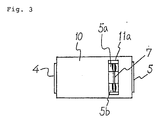
- the protective resin 11 is of a transparent one, the fuse connection can be confirmed from the outside through the projecting portion 11a as illustrated in Fig. 3, even after the connection has been enclosed by the molding resin 10.
- the protective resin 11 will change its color by the heat generated upon melting of the fuse.
- the fuse connection can easily be inspected while the capacitor is mounted on a circuit board.
- the above results are due to the fact that the cathode layer 3 of the capacitor element 1 is not located near the fuse 7 and the fact that, since the cathode terminal 5 illustrated in Figs. 2(a) and 2(b) can be manufactured by punching, flatness and dimension accuracy and uniformity are superior with a result of extremely stabilized properties of the fuse, and the like.
- the flatness and dimension accuracy and uniformity of the cathode terminal 5 are superior, it is possible to automatically connect the fuse 7 by the use of an automatic wire bonding machine.
- the manufacturing steps can extremely be simplified.
- the fuse 7, the connection portions thereof and the like are preliminarily covered completely with the protective resin 11, the fuse 7 is less likely to be subjected to a mechanical stress during the assembling step to-be broken or ruptured. Thus, the reliability is extremely improved.
- the projecting portion 11a of the protective resin 11 is abutted against a mold surface (not shown) for the molding resin 10 at the time of enclosure by the molding resin 10, so that there is no influence by the connection between the anode lead 2 and the anode terminal 4, and that the enclosing position of the cathode terminal 5 is stabilized. Accordingly, it is possible to reduce the thickness of the molding resin 10 interposed between the protective resin 11 and the outside, to 0.2 mm to 0.1 mm. As a result, the configuration of the capacitor element 1 can be increased.
Applications Claiming Priority (2)
| Application Number | Priority Date | Filing Date | Title |
|---|---|---|---|
| JP146402/91 | 1991-06-19 | ||
| JP3146402A JP2738168B2 (ja) | 1991-06-19 | 1991-06-19 | ヒューズ付きチップ状固体電解コンデンサ |
Publications (2)
| Publication Number | Publication Date |
|---|---|
| EP0519330A1 true EP0519330A1 (fr) | 1992-12-23 |
| EP0519330B1 EP0519330B1 (fr) | 1994-08-17 |
Family
ID=15406894
Family Applications (1)
| Application Number | Title | Priority Date | Filing Date |
|---|---|---|---|
| EP92109842A Expired - Lifetime EP0519330B1 (fr) | 1991-06-19 | 1992-06-11 | Condensateur à électrolyte solide du type puce avec fusible |
Country Status (4)
| Country | Link |
|---|---|
| US (1) | US5206798A (fr) |
| EP (1) | EP0519330B1 (fr) |
| JP (1) | JP2738168B2 (fr) |
| DE (1) | DE69200330T2 (fr) |
Cited By (4)
| Publication number | Priority date | Publication date | Assignee | Title |
|---|---|---|---|---|
| DE4311115A1 (de) * | 1992-04-07 | 1993-10-14 | Rohm Co Ltd | Festkörper-Elektrolyt-Kondensator |
| US5644281A (en) * | 1992-04-07 | 1997-07-01 | Rohm Co., Ltd. | Electronic component incorporating solder fuse wire |
| EP1720182A1 (fr) * | 2005-04-29 | 2006-11-08 | Salcomp Oyj | Protection d'un dispositif électrique contre l'explosion |
| EP2471079A2 (fr) * | 2009-08-24 | 2012-07-04 | Kemet Electronics Corporation | Condensateur de sécurité chargé de manière extérieure au moyen d'un fusible et d'une résistance |
Families Citing this family (6)
| Publication number | Priority date | Publication date | Assignee | Title |
|---|---|---|---|---|
| JP3877340B2 (ja) * | 1994-08-29 | 2007-02-07 | ローム株式会社 | 安全ヒューズ付パッケージ型固体電解コンデンサ |
| MY128095A (en) * | 1996-04-03 | 2007-01-31 | Matsushita Electric Ind Co Ltd | Electronic part and method for manufacturing the same |
| US6845004B2 (en) * | 2003-02-12 | 2005-01-18 | Kemet Electronics Corporation | Protecting resin-encapsulated components |
| US8717777B2 (en) | 2005-11-17 | 2014-05-06 | Avx Corporation | Electrolytic capacitor with a thin film fuse |
| US7532457B2 (en) * | 2007-01-15 | 2009-05-12 | Avx Corporation | Fused electrolytic capacitor assembly |
| JP2010251716A (ja) * | 2009-03-25 | 2010-11-04 | Rohm Co Ltd | 固体電解コンデンサおよびその製造方法 |
Citations (1)
| Publication number | Priority date | Publication date | Assignee | Title |
|---|---|---|---|---|
| EP0350366A1 (fr) * | 1988-07-04 | 1990-01-10 | Sprague France | Condensateur à électrolyte solide, notamment au tantale, à fusible incorporé |
Family Cites Families (3)
| Publication number | Priority date | Publication date | Assignee | Title |
|---|---|---|---|---|
| JPS5393781A (en) * | 1977-01-27 | 1978-08-17 | Toshiba Corp | Semiconductor device |
| US4763228A (en) * | 1987-11-20 | 1988-08-09 | Union Carbide Corporation | Fuse assembly for solid electrolytic capacitor |
| US4989119A (en) * | 1988-07-04 | 1991-01-29 | Sprague Electric Company | Solid electrolyte capacitor with testable fuze |
-
1991
- 1991-06-19 JP JP3146402A patent/JP2738168B2/ja not_active Expired - Fee Related
-
1992
- 1992-06-11 EP EP92109842A patent/EP0519330B1/fr not_active Expired - Lifetime
- 1992-06-11 DE DE69200330T patent/DE69200330T2/de not_active Expired - Fee Related
- 1992-06-17 US US07/899,849 patent/US5206798A/en not_active Expired - Fee Related
Patent Citations (1)
| Publication number | Priority date | Publication date | Assignee | Title |
|---|---|---|---|---|
| EP0350366A1 (fr) * | 1988-07-04 | 1990-01-10 | Sprague France | Condensateur à électrolyte solide, notamment au tantale, à fusible incorporé |
Non-Patent Citations (1)
| Title |
|---|
| PATENT ABSTRACTS OF JAPAN vol. 14, no. 320 (E-950)10 July 1990 & JP-A-2 106 024 ( MATSUSHITA ELECTRIC IND CO LTD ) 18 April 1990 * |
Cited By (8)
| Publication number | Priority date | Publication date | Assignee | Title |
|---|---|---|---|---|
| DE4311115A1 (de) * | 1992-04-07 | 1993-10-14 | Rohm Co Ltd | Festkörper-Elektrolyt-Kondensator |
| US5315474A (en) * | 1992-04-07 | 1994-05-24 | Rohm Co., Ltd. | Solid electrolytic capacitor |
| US5402307A (en) * | 1992-04-07 | 1995-03-28 | Kuriyama; Chojiro | Electronic component having fuse wire |
| US5644281A (en) * | 1992-04-07 | 1997-07-01 | Rohm Co., Ltd. | Electronic component incorporating solder fuse wire |
| EP1720182A1 (fr) * | 2005-04-29 | 2006-11-08 | Salcomp Oyj | Protection d'un dispositif électrique contre l'explosion |
| US7481849B2 (en) | 2005-04-29 | 2009-01-27 | Salcomp Oy | Protection of an inmoulded electric appliance against explosion |
| EP2471079A2 (fr) * | 2009-08-24 | 2012-07-04 | Kemet Electronics Corporation | Condensateur de sécurité chargé de manière extérieure au moyen d'un fusible et d'une résistance |
| EP2471079A4 (fr) * | 2009-08-24 | 2012-09-05 | Kemet Electronics Corp | Condensateur de sécurité chargé de manière extérieure au moyen d'un fusible et d'une résistance |
Also Published As
| Publication number | Publication date |
|---|---|
| DE69200330D1 (de) | 1994-09-22 |
| US5206798A (en) | 1993-04-27 |
| JPH04369821A (ja) | 1992-12-22 |
| DE69200330T2 (de) | 1995-03-30 |
| JP2738168B2 (ja) | 1998-04-08 |
| EP0519330B1 (fr) | 1994-08-17 |
Similar Documents
| Publication | Publication Date | Title |
|---|---|---|
| US4617609A (en) | Electric capacitor in the form of a chip component and method for manufacturing same | |
| KR910008074B1 (ko) | 퓨즈된 고체의 전해 캐패시터 | |
| TWI475590B (zh) | 具有表面安裝端蓋及增進之連接性的超小型保險絲 | |
| US6188566B1 (en) | Solid electrolytic capacitor having a second lead with a throughhole filled with an arc-extinguishing material | |
| US5478965A (en) | Fused chip-type solid electrolytic capacitor and fabrication method thereof | |
| US4763228A (en) | Fuse assembly for solid electrolytic capacitor | |
| US4814946A (en) | Fuse assembly for solid electrolytic capacitor | |
| EP0232868B1 (fr) | Condensateur à électrolyte solide muni d'un fusible | |
| EP0519330B1 (fr) | Condensateur à électrolyte solide du type puce avec fusible | |
| AU611082B2 (en) | Passive electronic component | |
| CN1763933B (zh) | 印刷电路板与结合其的电路单元 | |
| JPH07111938B2 (ja) | ヒューズ付きコンデンサ及びその組立に使用されるリードフレーム | |
| US5216584A (en) | Fused chip-type solid electrolytic capacitor and method of manufacturing the same | |
| JP2961734B2 (ja) | モールドチップタンタル固体電解コンデンサ | |
| JPH0545050B2 (fr) | ||
| JPH05101987A (ja) | ヒユーズ付きチツプ状固体電解コンデンサ | |
| JPH0436105Y2 (fr) | ||
| RU2013816C1 (ru) | Способ изготовления оксидно-полупроводниковых чип-конденсаторов | |
| JPH05234832A (ja) | ヒューズ付きチップ状固体電解コンデンサおよびその製造方法 | |
| JPS63265418A (ja) | ヒューズ付きチップ状固体電解コンデンサおよび製造方法 | |
| JP3067379B2 (ja) | ヒューズ付き固体電解コンデンサの製造方法 | |
| JPS62272516A (ja) | ヒユ−ズ付きチツプ型固体電解コンデンサ | |
| JP2850330B2 (ja) | ヒューズ付きチップ状固体電解コンデンサおよびその製造方法 | |
| JPS63232412A (ja) | ヒユ−ズ付きチツプ型電解コンデンサ | |
| JP2842067B2 (ja) | ヒューズ付きチップ固体電解コンデンサ |
Legal Events
| Date | Code | Title | Description |
|---|---|---|---|
| PUAI | Public reference made under article 153(3) epc to a published international application that has entered the european phase |
Free format text: ORIGINAL CODE: 0009012 |
|
| AK | Designated contracting states |
Kind code of ref document: A1 Designated state(s): DE FR GB |
|
| 17P | Request for examination filed |
Effective date: 19930107 |
|
| 17Q | First examination report despatched |
Effective date: 19931124 |
|
| GRAA | (expected) grant |
Free format text: ORIGINAL CODE: 0009210 |
|
| AK | Designated contracting states |
Kind code of ref document: B1 Designated state(s): DE FR GB |
|
| REF | Corresponds to: |
Ref document number: 69200330 Country of ref document: DE Date of ref document: 19940922 |
|
| ET | Fr: translation filed | ||
| PLBE | No opposition filed within time limit |
Free format text: ORIGINAL CODE: 0009261 |
|
| STAA | Information on the status of an ep patent application or granted ep patent |
Free format text: STATUS: NO OPPOSITION FILED WITHIN TIME LIMIT |
|
| 26N | No opposition filed | ||
| PGFP | Annual fee paid to national office [announced via postgrant information from national office to epo] |
Ref country code: GB Payment date: 19990609 Year of fee payment: 8 |
|
| PGFP | Annual fee paid to national office [announced via postgrant information from national office to epo] |
Ref country code: FR Payment date: 19990610 Year of fee payment: 8 |
|
| PGFP | Annual fee paid to national office [announced via postgrant information from national office to epo] |
Ref country code: DE Payment date: 19990614 Year of fee payment: 8 |
|
| PG25 | Lapsed in a contracting state [announced via postgrant information from national office to epo] |
Ref country code: GB Free format text: LAPSE BECAUSE OF NON-PAYMENT OF DUE FEES Effective date: 20000611 |
|
| GBPC | Gb: european patent ceased through non-payment of renewal fee |
Effective date: 20000611 |
|
| PG25 | Lapsed in a contracting state [announced via postgrant information from national office to epo] |
Ref country code: FR Free format text: LAPSE BECAUSE OF NON-PAYMENT OF DUE FEES Effective date: 20010228 |
|
| REG | Reference to a national code |
Ref country code: FR Ref legal event code: ST |
|
| PG25 | Lapsed in a contracting state [announced via postgrant information from national office to epo] |
Ref country code: DE Free format text: LAPSE BECAUSE OF NON-PAYMENT OF DUE FEES Effective date: 20010403 |