EP0519130A1 - Vorrichtung zur Herstellung von Profilleisten durch Extrudieren in einer offenen Form - Google Patents
Vorrichtung zur Herstellung von Profilleisten durch Extrudieren in einer offenen Form Download PDFInfo
- Publication number
- EP0519130A1 EP0519130A1 EP19910305539 EP91305539A EP0519130A1 EP 0519130 A1 EP0519130 A1 EP 0519130A1 EP 19910305539 EP19910305539 EP 19910305539 EP 91305539 A EP91305539 A EP 91305539A EP 0519130 A1 EP0519130 A1 EP 0519130A1
- Authority
- EP
- European Patent Office
- Prior art keywords
- plastic material
- cavity
- molding
- shaping
- ribbon
- Prior art date
- Legal status (The legal status is an assumption and is not a legal conclusion. Google has not performed a legal analysis and makes no representation as to the accuracy of the status listed.)
- Ceased
Links
Images


Classifications
-
- B—PERFORMING OPERATIONS; TRANSPORTING
- B29—WORKING OF PLASTICS; WORKING OF SUBSTANCES IN A PLASTIC STATE IN GENERAL
- B29C—SHAPING OR JOINING OF PLASTICS; SHAPING OF MATERIAL IN A PLASTIC STATE, NOT OTHERWISE PROVIDED FOR; AFTER-TREATMENT OF THE SHAPED PRODUCTS, e.g. REPAIRING
- B29C31/00—Handling, e.g. feeding of the material to be shaped, storage of plastics material before moulding; Automation, i.e. automated handling lines in plastics processing plants, e.g. using manipulators or robots
- B29C31/04—Feeding of the material to be moulded, e.g. into a mould cavity
- B29C31/042—Feeding of the material to be moulded, e.g. into a mould cavity using dispensing heads, e.g. extruders, placed over or apart from the moulds
- B29C31/044—Feeding of the material to be moulded, e.g. into a mould cavity using dispensing heads, e.g. extruders, placed over or apart from the moulds with moving heads for distributing liquid or viscous material into the moulds
- B29C31/045—Feeding of the material to be moulded, e.g. into a mould cavity using dispensing heads, e.g. extruders, placed over or apart from the moulds with moving heads for distributing liquid or viscous material into the moulds moving along predetermined circuits or distributing the material according to predetermined patterns
-
- B—PERFORMING OPERATIONS; TRANSPORTING
- B29—WORKING OF PLASTICS; WORKING OF SUBSTANCES IN A PLASTIC STATE IN GENERAL
- B29C—SHAPING OR JOINING OF PLASTICS; SHAPING OF MATERIAL IN A PLASTIC STATE, NOT OTHERWISE PROVIDED FOR; AFTER-TREATMENT OF THE SHAPED PRODUCTS, e.g. REPAIRING
- B29C43/00—Compression moulding, i.e. applying external pressure to flow the moulding material; Apparatus therefor
- B29C43/02—Compression moulding, i.e. applying external pressure to flow the moulding material; Apparatus therefor of articles of definite length, i.e. discrete articles
- B29C43/021—Compression moulding, i.e. applying external pressure to flow the moulding material; Apparatus therefor of articles of definite length, i.e. discrete articles characterised by the shape of the surface
-
- B—PERFORMING OPERATIONS; TRANSPORTING
- B29—WORKING OF PLASTICS; WORKING OF SUBSTANCES IN A PLASTIC STATE IN GENERAL
- B29C—SHAPING OR JOINING OF PLASTICS; SHAPING OF MATERIAL IN A PLASTIC STATE, NOT OTHERWISE PROVIDED FOR; AFTER-TREATMENT OF THE SHAPED PRODUCTS, e.g. REPAIRING
- B29C43/00—Compression moulding, i.e. applying external pressure to flow the moulding material; Apparatus therefor
- B29C43/22—Compression moulding, i.e. applying external pressure to flow the moulding material; Apparatus therefor of articles of indefinite length
- B29C43/224—Compression moulding, i.e. applying external pressure to flow the moulding material; Apparatus therefor of articles of indefinite length having a profiled section, e.g. tubes, rods
-
- B—PERFORMING OPERATIONS; TRANSPORTING
- B29—WORKING OF PLASTICS; WORKING OF SUBSTANCES IN A PLASTIC STATE IN GENERAL
- B29C—SHAPING OR JOINING OF PLASTICS; SHAPING OF MATERIAL IN A PLASTIC STATE, NOT OTHERWISE PROVIDED FOR; AFTER-TREATMENT OF THE SHAPED PRODUCTS, e.g. REPAIRING
- B29C43/00—Compression moulding, i.e. applying external pressure to flow the moulding material; Apparatus therefor
- B29C43/32—Component parts, details or accessories; Auxiliary operations
- B29C43/34—Feeding the material to the mould or the compression means
-
- B—PERFORMING OPERATIONS; TRANSPORTING
- B29—WORKING OF PLASTICS; WORKING OF SUBSTANCES IN A PLASTIC STATE IN GENERAL
- B29C—SHAPING OR JOINING OF PLASTICS; SHAPING OF MATERIAL IN A PLASTIC STATE, NOT OTHERWISE PROVIDED FOR; AFTER-TREATMENT OF THE SHAPED PRODUCTS, e.g. REPAIRING
- B29C43/00—Compression moulding, i.e. applying external pressure to flow the moulding material; Apparatus therefor
- B29C43/32—Component parts, details or accessories; Auxiliary operations
- B29C43/36—Moulds for making articles of definite length, i.e. discrete articles
- B29C43/3697—Moulds for making articles of definite length, i.e. discrete articles comprising rollers or belts cooperating with non-rotating mould parts
-
- B—PERFORMING OPERATIONS; TRANSPORTING
- B29—WORKING OF PLASTICS; WORKING OF SUBSTANCES IN A PLASTIC STATE IN GENERAL
- B29C—SHAPING OR JOINING OF PLASTICS; SHAPING OF MATERIAL IN A PLASTIC STATE, NOT OTHERWISE PROVIDED FOR; AFTER-TREATMENT OF THE SHAPED PRODUCTS, e.g. REPAIRING
- B29C48/00—Extrusion moulding, i.e. expressing the moulding material through a die or nozzle which imparts the desired form; Apparatus therefor
- B29C48/03—Extrusion moulding, i.e. expressing the moulding material through a die or nozzle which imparts the desired form; Apparatus therefor characterised by the shape of the extruded material at extrusion
- B29C48/12—Articles with an irregular circumference when viewed in cross-section, e.g. window profiles
-
- B—PERFORMING OPERATIONS; TRANSPORTING
- B29—WORKING OF PLASTICS; WORKING OF SUBSTANCES IN A PLASTIC STATE IN GENERAL
- B29C—SHAPING OR JOINING OF PLASTICS; SHAPING OF MATERIAL IN A PLASTIC STATE, NOT OTHERWISE PROVIDED FOR; AFTER-TREATMENT OF THE SHAPED PRODUCTS, e.g. REPAIRING
- B29C43/00—Compression moulding, i.e. applying external pressure to flow the moulding material; Apparatus therefor
- B29C43/32—Component parts, details or accessories; Auxiliary operations
- B29C43/34—Feeding the material to the mould or the compression means
- B29C2043/3433—Feeding the material to the mould or the compression means using dispensing heads, e.g. extruders, placed over or apart from the moulds
-
- B—PERFORMING OPERATIONS; TRANSPORTING
- B29—WORKING OF PLASTICS; WORKING OF SUBSTANCES IN A PLASTIC STATE IN GENERAL
- B29C—SHAPING OR JOINING OF PLASTICS; SHAPING OF MATERIAL IN A PLASTIC STATE, NOT OTHERWISE PROVIDED FOR; AFTER-TREATMENT OF THE SHAPED PRODUCTS, e.g. REPAIRING
- B29C48/00—Extrusion moulding, i.e. expressing the moulding material through a die or nozzle which imparts the desired form; Apparatus therefor
-
- B—PERFORMING OPERATIONS; TRANSPORTING
- B29—WORKING OF PLASTICS; WORKING OF SUBSTANCES IN A PLASTIC STATE IN GENERAL
- B29L—INDEXING SCHEME ASSOCIATED WITH SUBCLASS B29C, RELATING TO PARTICULAR ARTICLES
- B29L2007/00—Flat articles, e.g. films or sheets
- B29L2007/007—Narrow strips, e.g. ribbons, tapes, bands
-
- B—PERFORMING OPERATIONS; TRANSPORTING
- B29—WORKING OF PLASTICS; WORKING OF SUBSTANCES IN A PLASTIC STATE IN GENERAL
- B29L—INDEXING SCHEME ASSOCIATED WITH SUBCLASS B29C, RELATING TO PARTICULAR ARTICLES
- B29L2031/00—Other particular articles
- B29L2031/30—Vehicles, e.g. ships or aircraft, or body parts thereof
- B29L2031/3005—Body finishings
Definitions
- plastic automotive trim strips have been manufactured either by injection molding or by extrusion molding of the part desired to be affixed to the viewing surface of an automotive vehicle.
- extrusion molding is preferred as it is significantly less expensive than injection molding.
- extrusion molding has certain limitations including the fact that the side edges of the article as extruded will be straight and parallel and the ends of each cut-to-length strip will show the cross sectional interior of the extruded material unless such ends are reworked or have separately molded end caps applied.
- certain parts such as those for trim around the wheel wells have more complex shapes and are typically formed by injection molding.
- a method of extrusion molding and automotive trim strip is disclosed in United States Patent No. 4,722,818. Under such patent, the trim strip is made by extruding a thermoplastic material through an extrusion passageway, passing a film strip through a guide passageway in a novel die assembly and then bonding the film strip and the thermoplastic material into engagement.
- United States Patent No. 4,719,067 discloses a method of forming an end piece by injection molding onto a previously formed trim strip.
- United States Patent No. 4,489,019 discloses a method for producing longitudinal moldings with non-uniform sections without the use of an injection molding machine. Under the invention disclosed therein, one part of the molding is formed by extrusion molding and another part is remolded or reshaped to the desired cross-sectional configuration.
- U.S. Patent No. 4,489,019 discloses another method for forming a molding in part by extrusion molding and in part by remolding or reshaping.
- This invention relates to a method and apparatus for forming automotive trim strips by extruding a ribbon of heated plastic material into an open-faced mold having a molding surface and compressing a rotary forming mechanism against such ribbon to force the plastic material into conformity with the molding surface while simultaneously shaping the opposite side of the trim strip with the forming mechanism and to an article formed by such method.
- the automotive vehicle A has a wheel well trim strip W and a rear/side trim strip R.
- the wheel well trim strip W as affixed to the vehicle A has substantially the same shape as it had upon removal from the mold.
- the trim strip R is flat as molded but becomes curved when wrapped around the corner joining the side S and back B of the vehicle A.
- the wheel well trim strip W has a viewing surface 1, a non-viewing surface 2 intended to face the vehicle A, an upper or outer edge 3 and an inner edge 4 which includes an inwardly extending flange 5.
- the wheel well trim strip W as molded, follows a curved path generally matching that of the wheel well of the vehicle A.
- an extruder generally designated by the numeral 10 having an hopper 11 for receiving pellets or granules of thermoplastic material such as polyvinyl chloride (PVC) or other suitable plastic, and feeding it to an elongated barrel 12 having a heater for melting the plastic material and a screw (not shown) for feeding the melted plastic material through the barrel 12.
- the hopper 11 and barrel 12 are supported on a support stand 13.
- the die head 16 Secured to the end of the barrel 12 is a downwardly extending neck 15 to which is attached a die head 16 for receiving the heated and plasticized PVC or other plastic material from the barrel 12.
- the die head 16 includes an outlet orifice 17 from which plastic material is extruded in the form of a ribbon 18.
- the orifice 17 may have any one of a wide variety of shapes and configurations with the result that the ribbon 18 of plastic material as extruded may have a wide variety of cross sectional configurations.
- the ribbon 18 preferably has a cross-sectional configuration which includes a substantially horizontal bottom portion 19, a substantially vertical edge portion 20 which will provide plastic material for shaping the flange 5 and an upturned portion 21 approximating the shape of the outer edge 3 of the wheel well trim strip W. It should be understood, however, that the ribbon 18 may have any one of a wide variety of cross sectional configurations. It is the final shaping of the plastic material according to the method to be described that determines the final contour of the finished trim strip W, the non-viewing surface 2 as well as the viewing surface 1. Thus, although it is preferred that the ribbon 18 have a cross-sectional shape approximating the shape of the finished wheel well trim strip W, it could have other configurations so long as there is a sufficient amount of plastic material to form all portions of the trim strip W.
- a shaping roller mechanism In close proximity to the extrusion die head 16 is a shaping roller mechanism generally designated by the numeral 25 rotationally supported on an axle 26 supported at each end by a pair of downwardly extending arms 27 fastened to an outwardly extending support arm 28.
- the support arm 28 may be rigidly connected to a rotatable shaft 22 extending from a gear box 29.
- a motor 24 powers the gear box 29 to rotate the shaft 22 slightly in a clockwise direction when it is desired to raise the shaping roller mechanism 25 and in a counterclockwise direction when it is desired to lower it.
- Other types of support means may be utilized for supporting the shaping roller mechanism 25; however, as will become clear from a description of the molding operation, it is preferred that the shaping roller mechanism 25 be yieldingly urged downwardly.
- a mold 30 Positioned beneath the die head 16 is a mold 30 having an open faced mold cavity 31 conforming to the desired exterior or viewing surface 1 of the trim strip W.
- the mold cavity 31 follows a curved path from one end 31A to the other end 31B having generally the contour of the wheel well of the vehicle A.
- the mold 30 is mounted on a table 35 having a mechanism (not shown) for moving the mold 30 rotationally and/or eccentrically and/or in a straight line path depending upon the specific end to end configuration of the mold cavity 31.
- the mold 30 is moved beneath the orifice 17 of the die head 16 so that the mold cavity 31 is positioned directly thereunder to receive the ribbon 18, starting with the one end 31A and then throughout the remainder of the mold cavity 31 to the opposite end 31B.
- the mold cavity 31 from end to end is in the shape of an arc of a circle, the mold 30 will be required to move only in a circular path beneath the die head 16.
- the mold be fixed and the die head 16 be movable in order to extrude the ribbon 18 throughout the length of the cavity 31.
- the shaping roller 25 passes thereover to compress the still hot moldable plastic material firmly into the mold cavity 31.
- the roller 25 could have a simple cylindrical shape.
- the shaping roller mechanism 25 since the wheel well trim strip W has a cross-sectional configuration in which the non-viewing or attaching surface 2 is contoured rather than flat, the shaping roller mechanism 25 must be contoured.
- the shaping roller mechanism 25 is formed with separate roller segments 25A, 25B, 25C, 25D, 25E and 25F which are independently mounted on the axle 26.
- Each of such roller segments has a different shape or contour and each abuts the adjacent segment so that as the roller mechanism 25 is rotated against to the extruded ribbon 18, it shapes the plastic material into conformity with the mold cavity 31 to form the viewing surface 1 and into conformity with the exterior surfaces of the respective roller segments 25A, 25B, 25C, 25D, 25E and 25F to form the non-viewing surface 2.
- the flange 5 is formed between the side of roller segment 25E and the opposing surface of the mold cavity 31 with the free end of the flange 5 formed by the roller segment 25F.
- the upper or outer edge 3 is formed by the roller segment 25A.
- the outer roller segments 25A and 25F in addition to shaping the outer edge 3 and free end of the flange 5, respectively, also ride across the upper surface of the mold 30. This coupled with the downward urging of the shaping roller mechanism insures that the non-viewing surface 2 is molded to the designed contour.
- the mold 30 is initially positioned with the mold cavity end 31A lying directly under the die head 16 and the shaping roller mechnism 25 positioned beyond the end 31A and resting upon the face of the mold 30.
- the roller mechanism 25 is preferably yieldingly urged downwardly and may ride up on the surface of the mold 31 when positioned beyond the end 31A of cavity 31.
- the mold 30 is caused to move rotationally or in other appropriate direction so that the ribbon 18 is deposited into the mold cavity throughout the full length thereof to the opposite end of 31B.
- the ribbon 18 of thermoplastic material is shaped by the roller mechanism 25 passing over the newly deposited ribbon 18 throughout the full length of the mold cavity of 31.
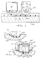
- Figs. 6-9 show apparatus for molding an article such as the rear/side trim strip R which is intended to be molded flat but bent around a corner when applied to the vehicle A.
- the surface to which rear/side trim strip R is to attached follows a curved path extending from the back B to the side S around the corner.
- the back B of the vehicle A is disposed at an angle or taper in the area to which the trim strip R is to be attached.
- a trim strip such as the trim strip R when wrapped around the back to the side of a vehicle will follow a curved path through a bend of approximately ninety degrees.
- those portions of the surface of the vehicle A to which the trim strip R is to be attached defined a shape in which all such portions from top to bottom were parallel to a vertical axis, it would be possible to simply form a straight, elongated trim strip and wrap it around the corner of a vehicle from one side to the rear. This could be readily accomplished on that type of surface even though the trim strip was straight as molded and fairly wide, for example, 2-4 inches.
- those portions of automotive vehicles to which trim strips are attached usually do not follow a path in which all portions are parallel to a vertical axis. Rather, they more frequently follow an path such as that shown in Fig.
- trim strip R when affixed to the vehicle A, will be horizontal or parallel to the bottom.
- the upper edge of such trim strip R must be longer than the lower edge. This is accomplished by molding the trim strip R to follow a curved path such as that shown in Fig. 6.
- the trim strip R may have a substantially planar non-viewing surface 101 and a contoured viewing surface 102.
- an extruder 10 and shaping roller mechanism 125 are positioned above a mold 130.
- the mold 130 has an open-faced cavity 131 which follows a straight path at each end with a curved path in the center joining the ends. Thus, the mold cavity extends from one end 131A, along a straight path to a curved section 131C, and then along a straight path in a different direction to the opposite end 131B.
- the molding surface of the mold cavity 131 may be contoured as at 132.
- the mold 130 has a short knife 133 encircling the mold cavity 131.
- the knife 133 extends upwardly from the face of the mold approximately .015 inches and terminates in a cutting edge 134.
- the knife 133 severs excess plastic material introduced into the mold cavity 131 from the die head 16.
- the mold 130 is mounted on a table 135 having a mechanism (not shown) for moving the mold 130 initially in a straight line path then in a curved path following the path of the curved section 131C and finally in a straight line path.
- the mold 130 is moved beneath the orifice 17' of the die head 16 so that the mold cavity 131 is positioned directly thereunder to receive the PVC or other plastic material starting with the one end 131A and then throughout the remainder of the mold cavity 131 to the opposite end 131B.
- the die head 16 may have an orifice 17' shaped to extrude a ribbon 18' having a generally rectangular configuration.
- a shaping roller mechanism 125 having a cylindrical configuration. Since the mold 130 will follow a curved path as the mold cavity curved section 131C passes beneath the shaping roller mechanism 125, it is desireable that the shaping roller mechanism 125 have independently rotatable roller segments 125A, 125B, 125C and 125D. The outer roller segments 125A and 125D extend beyond the opposite sides of the mold cavity 131 and engage the cutting edge 134 of the knife 133.
- the mold 130 is initially positioned with the mold cavity end 131A beneath the extrusion die head 16 and with the roller mechanism 125 contacting the face of the mold beyond the end 131A of the mold cavity 131.
- a ribbon 18' of plastic material is extruded from the orifice 17' and deposited throughout the length of the mold cavity 131 as the mold 130 moves beneath the die head 16.
- the amount of plastic material deposited in the cavity 131 will be slightly in excess of that needed to form the trim strip R.
- the shaping roller 125 passes thereover to compress the still hot moldable plastic material firmly into the mold cavity 131.
- a modified embodiment for producing a trim strip which is straight but which is tapered there is provided an elongated mold 145 having a mold cavity 146 extending from a first end 146A of a given width to an opposite end 146B which is substantially narrower.
- the mold 145 is mounted on a table 147 having a pair of guide channels 148. The mold 145 may be moved from a position at which the end 146A underlies the die head 16 to a position at which the opposite end 146B underlies the die head 16.
- a cylindrical roller 225 is mounted on an axle 226 supported in a support mechanism 227.
- the operation of this embodiment is substantially the same as the previous embodiment in that the roller 225 urges the heated and moldable plastic material firmly into the mold cavity 146 to form the finished article.
Landscapes
- Engineering & Computer Science (AREA)
- Mechanical Engineering (AREA)
- Robotics (AREA)
- Casting Or Compression Moulding Of Plastics Or The Like (AREA)
Applications Claiming Priority (1)
| Application Number | Priority Date | Filing Date | Title |
|---|---|---|---|
| US07/520,306 US5063014A (en) | 1990-05-07 | 1990-05-07 | Method for molding trim strips by extrusion molding in an open mold |
Publications (1)
| Publication Number | Publication Date |
|---|---|
| EP0519130A1 true EP0519130A1 (de) | 1992-12-23 |
Family
ID=24072032
Family Applications (1)
| Application Number | Title | Priority Date | Filing Date |
|---|---|---|---|
| EP19910305539 Ceased EP0519130A1 (de) | 1990-05-07 | 1991-06-19 | Vorrichtung zur Herstellung von Profilleisten durch Extrudieren in einer offenen Form |
Country Status (2)
| Country | Link |
|---|---|
| US (1) | US5063014A (de) |
| EP (1) | EP0519130A1 (de) |
Cited By (2)
| Publication number | Priority date | Publication date | Assignee | Title |
|---|---|---|---|---|
| EP0637520A2 (de) * | 1993-08-06 | 1995-02-08 | Toyota Jidosha Kabushiki Kaisha | Lenker aus faserverstärktem Kunststoff für eine Radaufhängung und Verfahren für seine Herstellung |
| WO2000053387A1 (en) * | 1999-03-10 | 2000-09-14 | Ttg Technology Transfer Gmbh | Method and apparatus for applying a plastic edge strip to a plate-like workpiece and such a workpiece |
Families Citing this family (16)
| Publication number | Priority date | Publication date | Assignee | Title |
|---|---|---|---|---|
| US5240751A (en) * | 1989-08-24 | 1993-08-31 | Aeroquip Corporation | Decorative plastic trim strip |
| US5108681A (en) * | 1989-08-24 | 1992-04-28 | Aeroquip Corporation | Decorative plastic trim strip and method and apparatus for forming |
| IT1250330B (it) * | 1991-10-31 | 1995-04-07 | Firestone Int Dev Spa | Metodo per la realizzazione di una testa anulare di battistrada senza giunzione. |
| US5266246A (en) * | 1991-11-19 | 1993-11-30 | Casco Tool & Extrusions, Inc. | Method of forming a molded plastic part |
| US5226998A (en) * | 1991-12-02 | 1993-07-13 | Plastic Trim, Inc. | Process for making a vehicle molding |
| US5746962A (en) * | 1995-01-13 | 1998-05-05 | Green Tokai Co., Ltd. | Method of insert molding plastic parts to provide covered edge surfaces |
| US5599608A (en) * | 1995-06-20 | 1997-02-04 | Green Tokai Co., Ltd. | Method of insert molding plastic parts to provide covered edge surfaces and plastic parts made thereby |
| US5759477A (en) * | 1996-12-13 | 1998-06-02 | Green Tokai Co. Ltd. | Method of making fused film plastic parts |
| US6168742B1 (en) | 1998-02-17 | 2001-01-02 | Green Tokai, Co., Ltd. | Method of insert molding auto and truck bumper, rocker panel and chin spoiler parts |
| US6231327B1 (en) * | 1999-07-02 | 2001-05-15 | Mastercraft Industries, L.P. | Composite extrusion and patterning machine for irregularly curved edges and method of manufacture thereof |
| WO2006081647A1 (en) * | 2005-02-04 | 2006-08-10 | Decoma International Inc. | Automotive trim strip from extruded thermoplastic materials |
| FR2939069B1 (fr) | 2008-11-28 | 2013-03-01 | Hexcel Reinforcements | Nouveau materiau intermediaire de largeur constante pour la realisation de pieces composites par procede direct. |
| USD807247S1 (en) * | 2014-11-12 | 2018-01-09 | Ronny Malina | Vehicle protector |
| US10449710B2 (en) | 2017-02-17 | 2019-10-22 | Thermwood Corporation | Methods and apparatus for compressing material during additive manufacturing |
| USD850344S1 (en) * | 2017-04-25 | 2019-06-04 | Lewis DeMatthews | Automobile door bumper |
| WO2019139594A1 (en) * | 2018-01-11 | 2019-07-18 | Hewlett-Packard Development Company, L.P. | Build material spreaders |
Citations (11)
| Publication number | Priority date | Publication date | Assignee | Title |
|---|---|---|---|---|
| US1811423A (en) * | 1927-05-27 | 1931-06-23 | John R Gammeter | Method and apparatus for filling molds |
| FR1066835A (fr) * | 1952-03-08 | 1954-06-10 | Vyzk Ustav Gumarenske Technolo | Procédé pour la fabrication d'objets en forme de bandes, en caoutchouc ou autres matières, moules pour la mise en oeuvre de ce procédé et objets obtenus suivant le procédé |
| US2774992A (en) * | 1949-10-04 | 1956-12-25 | Swedish Crucible Steel Company | Process of producing pearlescent plastic articles |
| US3237244A (en) * | 1962-11-01 | 1966-03-01 | Chemical Products Corp | Apparatus for making printing plates |
| US3470286A (en) * | 1965-08-09 | 1969-09-30 | Christine Weber | Manufacture of elongated resinous strips |
| FR2170879A1 (en) * | 1972-02-04 | 1973-09-21 | Kawaguchi Ltd | Continuous injection moulding plant - using multi impression tooling on endless conveyor |
| FR2348801A1 (fr) * | 1976-04-19 | 1977-11-18 | Minnesota Mining & Mfg | Procede et appareil de production d'une moulure de resine thermoplastique |
| FR2367179A1 (fr) * | 1976-10-06 | 1978-05-05 | Leopold Edmund | Procede pour la fabrication de fenetres a vitrage multiple |
| US4489019A (en) * | 1981-12-22 | 1984-12-18 | Aisin Seiki Kabushiki Kaisha | Method for producing a longitudinal molding with nonuniform sections |
| US4722818A (en) * | 1984-03-20 | 1988-02-02 | The Standard Products Company | Method for making an elongated composite article |
| US4751029A (en) * | 1985-04-15 | 1988-06-14 | Nicholas Plastics, Inc. | Method and means for molding plastic parts |
Family Cites Families (12)
| Publication number | Priority date | Publication date | Assignee | Title |
|---|---|---|---|---|
| NL6400607A (de) * | 1964-01-27 | 1965-07-28 | ||
| US3771938A (en) * | 1970-12-09 | 1973-11-13 | A Pinto | Apparatus for forming thin plastic packaging trays |
| US3917772A (en) * | 1972-02-10 | 1975-11-04 | Grace W R & Co | Method for producing battery separator sheet |
| US3914365A (en) * | 1973-01-16 | 1975-10-21 | Hercules Inc | Methods of making network structures |
| US4323533A (en) * | 1979-08-17 | 1982-04-06 | Monsanto Company | Rotary forming of articles |
| US4340557A (en) * | 1980-12-16 | 1982-07-20 | Ball Corporation | Method of making unfestooned plastic containers from polygonal blanks |
| US4631161A (en) * | 1983-01-18 | 1986-12-23 | Anatoliy Popow | Continuous molding method |
| JPS60154029A (ja) * | 1984-01-24 | 1985-08-13 | Ube Nitto Kasei Kk | 棒状連続押出成形体の整形方法および整形装置 |
| DE3420848A1 (de) * | 1984-06-05 | 1985-12-05 | Gebr. Happich Gmbh, 5600 Wuppertal | Verfahren und vorrichtung zum anbringen von endstuecken an kunststoff-profilleisten |
| DE3608813A1 (de) * | 1986-03-15 | 1987-09-17 | Dekora Design Wwd Werbe Und Wa | Verfahren und vorrichtung zur herstellung von nutringen |
| CH671184A5 (de) * | 1986-11-19 | 1989-08-15 | Bucher Guyer Ag Masch | |
| US4981637A (en) * | 1988-10-28 | 1991-01-01 | Jmk International, Inc. | Method of forming an improved wiper blade |
-
1990
- 1990-05-07 US US07/520,306 patent/US5063014A/en not_active Expired - Fee Related
-
1991
- 1991-06-19 EP EP19910305539 patent/EP0519130A1/de not_active Ceased
Patent Citations (11)
| Publication number | Priority date | Publication date | Assignee | Title |
|---|---|---|---|---|
| US1811423A (en) * | 1927-05-27 | 1931-06-23 | John R Gammeter | Method and apparatus for filling molds |
| US2774992A (en) * | 1949-10-04 | 1956-12-25 | Swedish Crucible Steel Company | Process of producing pearlescent plastic articles |
| FR1066835A (fr) * | 1952-03-08 | 1954-06-10 | Vyzk Ustav Gumarenske Technolo | Procédé pour la fabrication d'objets en forme de bandes, en caoutchouc ou autres matières, moules pour la mise en oeuvre de ce procédé et objets obtenus suivant le procédé |
| US3237244A (en) * | 1962-11-01 | 1966-03-01 | Chemical Products Corp | Apparatus for making printing plates |
| US3470286A (en) * | 1965-08-09 | 1969-09-30 | Christine Weber | Manufacture of elongated resinous strips |
| FR2170879A1 (en) * | 1972-02-04 | 1973-09-21 | Kawaguchi Ltd | Continuous injection moulding plant - using multi impression tooling on endless conveyor |
| FR2348801A1 (fr) * | 1976-04-19 | 1977-11-18 | Minnesota Mining & Mfg | Procede et appareil de production d'une moulure de resine thermoplastique |
| FR2367179A1 (fr) * | 1976-10-06 | 1978-05-05 | Leopold Edmund | Procede pour la fabrication de fenetres a vitrage multiple |
| US4489019A (en) * | 1981-12-22 | 1984-12-18 | Aisin Seiki Kabushiki Kaisha | Method for producing a longitudinal molding with nonuniform sections |
| US4722818A (en) * | 1984-03-20 | 1988-02-02 | The Standard Products Company | Method for making an elongated composite article |
| US4751029A (en) * | 1985-04-15 | 1988-06-14 | Nicholas Plastics, Inc. | Method and means for molding plastic parts |
Non-Patent Citations (1)
| Title |
|---|
| PATENT ABSTRACTS OF JAPAN vol. 9, no. 14 (M-352)(1737) 22 January 1985 & JP-A-59 164 112 ( TOYOTA JIDOSHA K. K. ) 17 September 1984 * |
Cited By (4)
| Publication number | Priority date | Publication date | Assignee | Title |
|---|---|---|---|---|
| EP0637520A2 (de) * | 1993-08-06 | 1995-02-08 | Toyota Jidosha Kabushiki Kaisha | Lenker aus faserverstärktem Kunststoff für eine Radaufhängung und Verfahren für seine Herstellung |
| EP0637520A3 (de) * | 1993-08-06 | 1995-11-08 | Toyota Motor Co Ltd | Lenker aus faserverstärktem Kunststoff für eine Radaufhängung und Verfahren für seine Herstellung. |
| US5556081A (en) * | 1993-08-06 | 1996-09-17 | Toyota Jidosha Kabushiki Kaisha | Suspension arm made of fiber reinforced plastic and manufacturing method thereof |
| WO2000053387A1 (en) * | 1999-03-10 | 2000-09-14 | Ttg Technology Transfer Gmbh | Method and apparatus for applying a plastic edge strip to a plate-like workpiece and such a workpiece |
Also Published As
| Publication number | Publication date |
|---|---|
| US5063014A (en) | 1991-11-05 |
Similar Documents
| Publication | Publication Date | Title |
|---|---|---|
| US5063014A (en) | Method for molding trim strips by extrusion molding in an open mold | |
| KR940000620B1 (ko) | 모울딩부재 및 그 제조방법 | |
| KR100212620B1 (ko) | 열가소성 물질로부터 스트립 생성물을 성형하는 방법 | |
| US5108681A (en) | Decorative plastic trim strip and method and apparatus for forming | |
| US5023033A (en) | Decorative plastic trim strip and method and apparatus for forming | |
| US5565053A (en) | Method of manufacturing a plastic molding | |
| JP4363784B2 (ja) | 対象物上に押し出されたプロファイルドビードの部分の成形方法と装置、およびこのような対象物を具備する物品 | |
| WO1997027989A1 (fr) | Element composite allonge dont la section transversale varie longitudinalement, procede et appareil pour sa fabrication | |
| US5846465A (en) | Method for preparing a plate member for a window with a resinous frame | |
| JPH0825385B2 (ja) | ウインドウモールディングおよびその製造方法 | |
| JPH044931B2 (de) | ||
| JPS6391222A (ja) | モ−ルデイングの製造方法 | |
| EP0805013B1 (de) | Vorrichtung zur Formung von extrudierten Dichtungsprofilen | |
| JPH0768620A (ja) | 合成樹脂枠体付き窓体の製造方法 | |
| US6464814B2 (en) | Method for molding an end of a long resin molded article | |
| JP3251185B2 (ja) | 自動車用ウィンドモール及びその製造方法 | |
| US4255107A (en) | Control apparatus for producing uniform thickness corrugated tubing | |
| JP2639086B2 (ja) | 樹脂成形品の製造方法 | |
| JPH05138714A (ja) | ウインドモールデイングの押出成形型 | |
| KR100313492B1 (ko) | 차량에 부착되는 몰딩의 제조방법 | |
| Cakmakei | Method and Apparatus for Molding Trim Strips by Extrusion Molding in an Open Mold and Article Produced Thereby | |
| JPS63242526A (ja) | モ−ルデイングの製造方法 | |
| JPH04347611A (ja) | 剛性の異なる押出体の模様付け型接続方法 | |
| JP3480007B2 (ja) | 三次元フランジを備えた押出形材の製造方法及び製造装置 | |
| KR20010000004A (ko) | 차량에 부착되는 몰딩의 제조방법 |
Legal Events
| Date | Code | Title | Description |
|---|---|---|---|
| PUAI | Public reference made under article 153(3) epc to a published international application that has entered the european phase |
Free format text: ORIGINAL CODE: 0009012 |
|
| AK | Designated contracting states |
Kind code of ref document: A1 Designated state(s): DE ES FR GB IT |
|
| RIN1 | Information on inventor provided before grant (corrected) |
Inventor name: CAKMAKCI, MEHMET YAVUZ |
|
| 17P | Request for examination filed |
Effective date: 19930420 |
|
| 17Q | First examination report despatched |
Effective date: 19940504 |
|
| STAA | Information on the status of an ep patent application or granted ep patent |
Free format text: STATUS: THE APPLICATION HAS BEEN REFUSED |
|
| 18R | Application refused |
Effective date: 19950708 |