EP0518286B1 - Video camera for camera system - Google Patents
Video camera for camera system Download PDFInfo
- Publication number
- EP0518286B1 EP0518286B1 EP92109736A EP92109736A EP0518286B1 EP 0518286 B1 EP0518286 B1 EP 0518286B1 EP 92109736 A EP92109736 A EP 92109736A EP 92109736 A EP92109736 A EP 92109736A EP 0518286 B1 EP0518286 B1 EP 0518286B1
- Authority
- EP
- European Patent Office
- Prior art keywords
- image
- video
- view
- camera
- signal
- Prior art date
- Legal status (The legal status is an assumption and is not a legal conclusion. Google has not performed a legal analysis and makes no representation as to the accuracy of the status listed.)
- Expired - Lifetime
Links
Images







Classifications
-
- G—PHYSICS
- G03—PHOTOGRAPHY; CINEMATOGRAPHY; ANALOGOUS TECHNIQUES USING WAVES OTHER THAN OPTICAL WAVES; ELECTROGRAPHY; HOLOGRAPHY
- G03B—APPARATUS OR ARRANGEMENTS FOR TAKING PHOTOGRAPHS OR FOR PROJECTING OR VIEWING THEM; APPARATUS OR ARRANGEMENTS EMPLOYING ANALOGOUS TECHNIQUES USING WAVES OTHER THAN OPTICAL WAVES; ACCESSORIES THEREFOR
- G03B17/00—Details of cameras or camera bodies; Accessories therefor
- G03B17/18—Signals indicating condition of a camera member or suitability of light
- G03B17/20—Signals indicating condition of a camera member or suitability of light visible in viewfinder
-
- G—PHYSICS
- G03—PHOTOGRAPHY; CINEMATOGRAPHY; ANALOGOUS TECHNIQUES USING WAVES OTHER THAN OPTICAL WAVES; ELECTROGRAPHY; HOLOGRAPHY
- G03B—APPARATUS OR ARRANGEMENTS FOR TAKING PHOTOGRAPHS OR FOR PROJECTING OR VIEWING THEM; APPARATUS OR ARRANGEMENTS EMPLOYING ANALOGOUS TECHNIQUES USING WAVES OTHER THAN OPTICAL WAVES; ACCESSORIES THEREFOR
- G03B17/00—Details of cameras or camera bodies; Accessories therefor
- G03B17/48—Details of cameras or camera bodies; Accessories therefor adapted for combination with other photographic or optical apparatus
-
- H—ELECTRICITY
- H04—ELECTRIC COMMUNICATION TECHNIQUE
- H04N—PICTORIAL COMMUNICATION, e.g. TELEVISION
- H04N23/00—Cameras or camera modules comprising electronic image sensors; Control thereof
- H04N23/60—Control of cameras or camera modules
- H04N23/63—Control of cameras or camera modules by using electronic viewfinders
Definitions
- This invention relates to a video camera having a zoom function and including an electronic viewfinder.
- a video camera permits both a still image and a dynamic image to be obtained. Since the resolution of video cameras is lower than that of photographic cameras (film cameras), there is a demand for a combined use of a video camera and a photographic camera.
- a photographic camera may be firmly fixed to a video camera so that the shutter of the photographic camera can be operated while a dynamic image is recorded by the video camera.
- a camera system which includes a photographic camera of the still or motion picture type with an adjustable lens system and a TV camera with a fixed lens system. whereby the object angle of the photographic camera is less than or equal to the object angle of the TV camera.
- a circuit is provided to define the variable object field of the photographic camera by a luminous frame on a monitor screen also displaying the fixed object field of the TV camera.
- the JP-A-1-013 530 discloses a visual field expanded type camera for finder wherein the photographic range of a camera having a zoom lens is confirmed in a video picture of a video camera having a fixed focal length.
- the angle of view of a picked-up image changes as the zooming power is changed. This is the case with photographic cameras having a zoom function.
- An object of this invention is, therefore, to provide a video camera which permits the view field of a photographic camera to be accurately recognized even if the zooming power is changed.
- the image frame of the photographic camera is displayed at the electronic viewfinder on the basis of a picked-up image of fixed size. Accordingly, the view field of the photographic camera can be accurately recognized, whereby the user can correctly operate the shutter of the photographic camera while viewing the display screen of the electronic viewfinder.
- the embodiment comprises an integral combination of a video camera and a photographic camera.
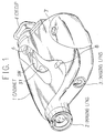
- FIG. 1 is a perspective view showing an entire arrangement, wherein reference numeral 1 denotes a cabinet which has a built-in video camera section including an imaging device, a signal processing circuit, etc., and a built-in photographic camera section including a film loading mechanism, a film drive mechanism, etc., none of which are shown.
- reference numeral 1 denotes a cabinet which has a built-in video camera section including an imaging device, a signal processing circuit, etc., and a built-in photographic camera section including a film loading mechanism, a film drive mechanism, etc., none of which are shown.
- Reference numeral 2 denotes an imaging lens of the video camera section
- 3 denotes an imaging lens of the photographic camera section.
- the optical system for the video camera section is separate from that for the photographic camera section.
- a 6-power zoom lens having a focal length f of 7 to 42 mm is used for the imaging lens 2
- a fixed-focus lens having a focal length f of 55 mm is used for the imaging lens 3.
- an electronic viewfinder comprising a small-sized CRT is arranged in the cabinet 1, for displaying an image picked up by the video camera section through the imaging lens 2.
- Reference numeral 4 represents an eyecup. There is provided no finder permitting a direct observation of an image to be photographed by the photographic camera section through the imaging lens 3.
- 5T and 5W denote zoom buttons for a zooming operation in a TELE direction and a WIDE direction, respectively, 6 denotes a record button for recording a video signal output from the video camera section in a VTR, 7 denotes a shutter button of the photographic camera section, and 8 denotes a film rewind button.
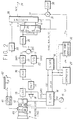
- FIG. 2 is a block diagram showing the arrangement of the video camera section. An image light from an object enters through the imaging lens 2 and an iris 11 and falls upon a single-plate CCD solid-state imaging device 12 having a complementary checkered color filter.
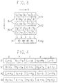
- FIG. 3 is a schematic diagram showing a color coding of the imaging device 12, and as illustrated, a field readout is carried out.
- a field charges are mixed in pairs, such as a pair of A1 and A2, and in B field, charges are mixed in pairs such as a pair of B1 and B2.
- B field charges are mixed in pairs such as a pair of B1 and B2.
- a field charges are output in the order of A1, A2, ..., and for the B field in the order of B1, B2, ..., from a horizontal shift register Hreg.
- the order of charges a, b, ... is (Cy + G), (Ye + Mg), ... in A1 line, (Cy + Mg), (Ye + G), ... in A2 line, (G + Cy), (Mg + Ye), ... in B1 line, and (Mg + Cy), (G + Ye), ... in B2 line.
- the charges output from the imaging device 12 in the aforementioned manner are supplied to a CDS circuit (correlation double sampling circuit) 13 and are extracted thereby to obtain an image signal.
- a CDS circuit correlation double sampling circuit
- Timing pulses needed by the imaging device 12 and the CDS circuit 13 are produced by a timing generator 14.
- the timing generator 14 is supplied with reference clock pulses CK0 at 8 fsc (fsc represents the color subcarrier frequency) from an oscillator 15, as well as horizontal and vertical synchronizing signals HD and VD from a synchronizing generator 16.
- the synchronizing generator 16 is supplied with clock pulses CK1 at 4 fsc from the timing generator 14.
- An image signal output from the CDS circuit 13 is supplied to a level detecting circuit 17, which outputs a signal to an iris driver 18.
- the iris driver 18 automatically controls the aperture of the iris 11.
- the luminance signal Y is obtained by adding adjacent signals together. Namely, referring to FIG. 4, summation signals are produced in the sequence of a + b, b + c, c + d, d + e, ....
- the chroma signal is obtained by subjecting adjacent signals to a subtraction.
- a red differential signal R - Y and a blue differential signal -(B - Y) are alternately derived in a line sequential manner.
- the image signal output from the CDS circuit 13 is supplied to a low-pass filter 20 constituting a luminance processing unit through an AGC circuit 19.
- the low-pass filter 20 carries out an addition (averaging) of adjacent signals, and accordingly, a luminance signal Y is output therefrom.
- the image signal output from the AGC circuit 19 is supplied to sample holding circuits 21 and 22 forming a chroma processing unit.
- the sample holding circuits 21 and 22 are supplied with sampling pulses SHP1 and SHP2 (shown in FIGS. 5 and 6 at E and F), respectively, from the timing generator 14.
- the sample holding circuit 21 outputs a continuous signal S1 of (Cy + G) or (Cy + Mg) to a subtracter 23 (see B of FIGS. 5 and 6), and the sample holding circuit 22 outputs a continuous signal S2 of (Ye + Mg) or (Ye + G) to the subtracter 23 (see C of FIGS. 5 and 6).
- the subtracter 23 subtracts the signal S1 from the signal S2, whereby a red differential signal R - Y and a blue differential signal -(B - Y) are alternately output therefrom in a line sequential manner (as shown at D in FIGS. 5 and 6).
- the color differential signals output from the subtracter 23 are supplied directly to a fixed terminal b of a changeover switch 24 and a fixed terminal a of a changeover switch 25, and also supplied to a fixed terminal a of the changeover switch 24 and a fixed terminal b of the changeover switch 25 via a delay circuit 26 having a delay time corresponding to one horizontal period.
- the switching operation of the changeover switches 24 and 25 is controlled by a controller 27. Specifically, the switches connect to the respective terminals b during a horizontal period in which the red differential signal R - Y is output from the subtracter 23, and connect to the respective terminals a during a horizontal period in which the blue differential signal -(B - Y) is output.
- the controller 27 is supplied with the synchronizing signals HD and VD as reference synchronizing signals from the synchronizing generator 16, and the clock pulses CK1 from the timing generator 14.
- a red differential signal R - Y is output from the changeover switch 24 in each horizontal period and a blue differential signal -(B - Y) is output from the changeover switch 25 in each horizontal period.
- the luminance signal Y output from the low-pass filter 20 and the color differential signals (R - Y) and -(B - Y) output from the changeover switches 24 and 25 are supplied to an encoder 28.
- the encoder 28 is further supplied with a composite synchronizing signal SYNC, a blanking signal BLK, a burst flag signal BF, and a color subcarrier signal SC from the synchronizing generator 16.
- the luminance signal Y is combined with the synchronizing signal SYNC, and the color differential signals are subjected to quadrature two-phase modulation to form a carrier chrominance signal C and further combined with a color burst signal.
- the luminance signal Y and the carrier chrominance signal C are added together to form, e.g., a color video signal SCV according to the NTSC system.
- the color video signal SCV thus generated by the encoder 28 appears at an output terminal 29.
- the encoder 28 also generates a monochromatic video signal SV (i.e., the luminance signal Y combined with the synchronizing signal SYNC), which is supplied to an electronic viewfinder 30 through an adder 31.
- a picked-up image is displayed at the small-sized CRT constituting the electronic viewfinder 30.
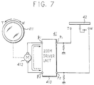
- FIG. 7 shows in detail the arrangement of the zoom driver 41, wherein reference numeral 411 denotes a lens constituting the imaging lens 2 for adjusting the zooming power.
- the lens 411 can be moved back and forth when rotated, whereby the zooming power is adjusted. For example, if the lens 411 is rotated in a direction T, the zooming power changes in the TELE direction; if the lens is rotated in a direction W, then the zooming power changes in the WIDE direction.
- the lens 411 is rotated by a DC motor 412, which is connected to output terminals q1 and q2 of a zoom driver unit 413.
- Input terminals p1 and p2 of the zoom driver unit 413 are respectively connected to fixed terminals T and W of a zoom switch 42.
- a movable terminal of the zoom switch 42 is connected to a power supply terminal.
- the zoom switch 42 is connected to the terminal T or W, and a high-level "H" signal is supplied to the terminal p1 or p2 of the zoom driver unit 413, whereby the zooming power is adjusted in the TELE or WIDE direction.
- a variable resistor 44 constituting a potentiometer is arranged at a location where the lens 411 of the imaging lens 2 is mounted.
- the variable resistor 44 is constructed such that the position of a movable terminal thereof is shifted with a rotation of the lens 411, whereby a voltage corresponding to the zooming power builds up at the movable terminal and is applied to the controller 27 as a detection signal SD.
- a picked-up image is displayed at a fixed position on the screen of the small-sized CRT of the electronic viewfinder 30, and at the same time an image frame of the photographic camera is displayed on the same screen.
- the angle of view of a picked-up image changes in accordance with the zooming power, and thus the view field thereof changes accordingly.
- the ratio of the view fields of the photographic camera and the picked-up image must be obtained.
- the angle of view can be obtained from an image plane size T and the value f (focal length), as shown in equation (1) below.
- T' denotes the view field
- L denotes the distance to an object.
- the imaging lens 2 is a 6-power zoom lens having a focal length f of 7 to 42 mm, and where the imaging device 12 is a 1/3-inch type, the image plane having a horizontal size ZH of 4.9 mm, a vertical size ZV of 3.69 mm, and a diagonal size ZD of 6.13 mm (see FIG. 10).
- the imaging lens 3 is a fixed-focus lens having a focal length f of 55 mm, and where the film used is a 35 mm type, the image plane having a horizontal size PH of 36 mm, a vertical size PV of 24 mm, and a diagonal size PD of 43.3 mm (see FIG. 11).
- angles ⁇ PH, ⁇ PV and ⁇ PD of view in the horizontal, vertical and diagonal directions are 36.2°, 24.6°, and 43.0°, respectively.
- the view field ratio is found to vary as a function of view angle ⁇ .
- view fields T'ZH and T'ZV in the horizontal and vertical directions at the WIDE end are 0.7L and 0.53L, respectively, and view fields T'ZH and T'ZV in the horizontal and vertical directions at the TELE end are 0.12L and 0.09L, respectively.
- view fields T'PH and T'PV in the horizontal and vertical directions are 0.65L and 0.44L, respectively.
- FIG. 12 shows the relationship of the horizontal view fields
- FIG. 13 shows the relationship of the vertical view fields.
- Table 3 shows view field ratios T'PH/T'ZH and T'PV/T'ZV in the horizontal and vertical directions, respectively.
- TABLE 3 Picked-up image WIDE - TELE View field ratio T'PH/T'ZH in horizontal direction 0.93 to 5.42 View field ratio T'PV/T'ZV in vertical direction 0.83 to 4.89
- the focal length f obtained by equation (5), is substituted into equation (4) and the horizontal and vertical sizes ZH and ZV of the image plane are substituted individually for T in equation (4), whereby the horizontal and vertical view fields T'ZH and T'ZV are obtained.
- the controller 27 generates image frame data Dm for displaying the image frame of the photographic camera at a position corresponding to the horizontal and vertical view field ratios T'PH/T'ZH and T'PV/T'ZV.
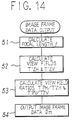
- FIG. 14 is a flowchart showing an image frame data output process executed by the controller 27.
- the focal length f is computed from the detection signal SD, using equation (5) (Step 51).
- the focal length f is substituted into equation (4), and the horizontal and vertical sizes ZH and ZV of the image plane are substituted individually for T in equation (4), to thereby obtain horizontal and vertical view fields T'ZH and T'ZV of the picked-up image (Step 52).
- image frame data Dm corresponding to the view field ratios T'PH/T'ZH and T'PV/T'ZV is output (Step 54).
- the image frame data Dm is used, e.g., for an image frame signal to indicate horizontal and vertical positions.
- the image frame data Dm is generated based on the horizontal and vertical display lengths of a picked-up image of fixed size such that the horizontal and vertical lengths of the image frame are substantially equal to the corresponding lengths specified by the view field ratios T'PH/T'ZH and T'PV/T'ZV.
- the horizontal length of the image frame is adjusted in units of pixel pitch, and the vertical length of the same is adjusted in units of line pitch.
- the image frame data Dm output from the controller 27 is supplied to a frame signal generating circuit 32.
- the frame signal generating circuit 32 is also supplied with the synchronizing signals HD and VD from the synchronizing generator 16, and the clock pulses CK1 from the timing generator 14.
- the frame signal generating circuit 32 outputs, e.g., a white peak level signal at times corresponding to the horizontal and vertical positions specified by the image frame data Dm, and this signal is supplied to the adder 31 as a frame signal Sm to be added to the monochromatic video signal SV.
- a picked-up image as shown in FIG. 15 and the image frame of the photographic camera are displayed on the screen of the small-sized CRT of the electronic viewfinder 30.
- the image frame of the photographic camera is displayed at a location corresponding to the zooming power.
- the size of the picked-up image is previously reduced to such an extent that the image frame of the photographic camera at the TELE end can be displayed, and the picked-up image is shown at the center of the screen of the small-sized CRT.
- a time base compressing process for such an image reduction is executed, e.g., by the encoder 28.
- the image frame of the photographic camera is displayed on the screen of the small-sized CRT of the electronic viewfinder 30 on the basis of the picked-up image of fixed size, the view field of the photographic camera can be accurately recognized even if the zooming power is changed. Accordingly, the user can correctly release the shutter of the photographic camera while viewing the display screen of the electronic viewfinder 30.
- this invention can be applied to a video camera to which a separate photographic camera is firmly fixed.
- input means for inputting e.g., data representing the view fields T'PH and T'PV of the photographic camera (or data of the view angles ⁇ PH and ⁇ PV, or data representing the focal length f and the image plane size, PH and PV, of the film used) to the controller 27 may be provided, whereby the invention can be applied to any type of photographic cameras.
- FIG. 16 is a block diagram showing the arrangement of a video camera section according to this embodiment.
- the same reference numerals are used to denote corresponding parts in FIG. 2, and a detailed description thereof is omitted.
- a monochromatic video signal SV output from an encoder 28 is supplied to an electronic viewfinder 30 through an adder 31, and a picked-up image is displayed at a small-sized CRT constituting the electronic viewfinder 30.
- a zoom driver 41 in FIG. 16 has an arrangement shown in FIG. 17.
- reference numeral 411 represents a lens which constitutes an imaging lens 2 and is used to adjust the zooming power.
- the lens 411 can be moved back and forth when rotated, whereby the zooming power is adjusted. For example, when the lens 411 is rotated in a direction T, the zooming power changes in the TELE direction; when the lens is rotated in a direction W, the zooming power changes in the WIDE direction.
- the lens 411 is rotated by a DC motor 412, which is connected to output terminals q1 and q2 of a zoom driver unit 413.
- Input terminals p1 and p2 of the zoom driver unit 413 are connected, respectively, to fixed terminals T and W of a zoom switch 42 through terminals v of respective changeover switches 45 and 46.
- the switching of the changeover switches 45 and 46 is carried out by a zoom selection button (not shown in FIG. 1) arranged in the cabinet 1.
- a zoom selection button (not shown in FIG. 1) arranged in the cabinet 1.
- the switches 45 and 46 are connected to the respective terminals v, and when the button is pressed, the switches are connected to respective terminals p.
- a movable terminal of the zoom switch 42 is connected to a power supply terminal.
- the zoom switch 42 is connected to the terminal T or W.
- a high-level "H" signal is supplied to the terminal p1 or p2 of the zoom driver unit 413, whereby the zooming power is adjusted in the TELE or WIDE direction.
- a variable resistor 44 constituting a potentiometer is arranged at a location where the lens 411 of the imaging lens 2 is mounted.
- the variable resistor 44 is constructed such that the position of a movable terminal thereof is shifted as the lens 411 is rotated, whereby a voltage corresponding to the zooming power appears at the movable terminal and is applied to the controller 27 as a detection signal SDv.
- a 3-power zoom lens having a focal length f of 35 to 105 mm is used for the imaging lens 3 of the photographic camera section, and the zooming power of the imaging lens 3 is adjusted by a zoom driver 47.
- FIG. 19 shows the arrangement of the zoom driver 47 in detail.
- This zoom driver 47 has an arrangement similar to that of the aforementioned zoom driver 41, and therefore, the same reference numerals are used to represent corresponding parts and a detailed description thereof is omitted.
- Input terminals p1 and p2 of a zoom driver unit 413 of the zoom driver 47 are connected to fixed terminals T and W of a zoom switch 42 through terminals p of changeover switches 45 and 46, respectively.
- the zoom switch 42 When the operating button 5T or 5W of the cabinet 1 is pressed, the zoom switch 42 is connected to the terminal T or W.
- a high-level "H" signal is supplied to the terminal p1 or p2 of the zoom driver unit 413, whereby the zooming power is adjusted in the TELE or WIDE direction.
- a variable resistor 48 constituting a potentiometer is arranged at a location where the lens 411 of the imaging lens 3 is mounted.
- the variable resistor 48 is constructed such that the position of a movable terminal thereof is shifted as the lens 411 is rotated, whereby a voltage corresponding to the zooming power appears at the movable terminal and is applied to the controller 27 as a detection signal SDp.
- a picked-up image is displayed at a fixed position on the screen of the small-sized CRT of the electronic viewfinder 30, and at the same time, an image frame of the photographic camera is displayed on the same screen.
- the angles of view of the video camera and the photographic camera change in accordance with the zooming power, and thus the view fields thereof change accordingly.
- the ratio of the view fields of the picked-up image and the photographic camera must be obtained.
- the view angle ⁇ can be obtained from the image plane size T and the value f (focal length), using the above equation (1) and based on FIG. 9.
- the imaging lens 2 is a 6-power zoom lens having an f value of 7 to 42 mm.
- the image plane has a horizontal size ZH of 4.9 mm, a vertical size ZV of 3.69 mm, and a diagonal size ZD of 6.13 mm (see FIG. 10).
- the imaging lens 3 is a 3-power zoom lens having an f value of 35 to 105 mm.
- the image plane has a horizontal size PH of 36 mm, a vertical size PV of 24 mm, and a diagonal size PD of 43.3 mm (see FIG. 11).
- the view field ratio is found to vary as a function of view angle ⁇ .
- view fields T'ZH and T'ZV in the horizontal and vertical directions at the WIDE end are 0.7L and 0.53L, respectively, and view fields T'ZH and T'ZV in the horizontal and vertical directions at the TELE end are 0.12L and 0.09L, respectively.
- view fields T'PH and T'PV in the horizontal and vertical directions at the WIDE end are 1.03L and 0.69L, respectively, and view fields T'PH and T'PV in the horizontal and vertical directions at the TELE end are 0.34L and 0.23L, respectively.
- the view fields T'PH and T'PV can be obtained.
- FIG. 21 shows the relationship of the view fields in the horizontal direction
- FIG. 22 shows the relationship of the view fields in the vertical direction.
- view field ratios T'PH/T'ZH and T'PV/T'ZV in the horizontal and vertical directions become as shown in Table 7.
- Table 7 View field ratio T'PH/T'ZH in horizontal direction 0.49 to 8.58 View field ratio T'PV/T'ZV in vertical direction 0.43 to 7.67
- the view field T' can also be obtained as shown in the aforementioned equation (4).
- the focal length f obtained by equation (8), is substituted into equation (4) and the horizontal and vertical sizes ZH and ZV of the image plane are substituted individually for T in equation (4), whereby the horizontal and vertical view fields T'ZH and T'ZV are obtained.
- the controller 27 generates image frame data Dm for displaying the image frame of the photographic camera at a location on the display screen corresponding to the horizontal and vertical view field ratios T'PH/T'ZH and T'PV/T'ZV.
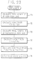
- FIG. 23 is a flowchart showing an image frame data output process executed by the controller 27.
- the focal length f of the imaging lens 2 is computed from the detection signal SDv, using equation (8) (Step 71).
- the obtained focal length f is substituted into equation (4), and the horizontal and vertical sizes ZH and ZV of the image plane are substituted individually for T in equation (4), to thereby obtain horizontal and vertical view fields T'ZH and T'ZV of the video camera (Step 72).
- the focal length f of the imaging lens 3 is then calculated from the detection signal SDp, using equation (9) (Step 73).
- the thus-obtained focal length f is substituted into equation (4), and the horizontal and vertical sizes PH and PV of the image plane are substituted individually for T in equation (4), to thereby obtain horizontal and vertical view fields T'PH and T'PV of the photographic camera (Step 74).
- image frame data Dm corresponding to the view field ratios T'PH/T'ZH and T'PV/T'ZV is output (Step 76).
- the image frame data Dm is used. e.g., for an image frame signal to indicate horizontal and vertical positions.
- the image frame data Dm is generated based on the horizontal and vertical display lengths of a picked-up image of fixed size such that the horizontal and vertical lengths of the image frame are substantially equal to the corresponding lengths determined by the view field ratios T'PH/T'ZH and T'PV/T'ZV.
- the horizontal length of the image frame is adjusted in units of pixel pitch, and the vertical length of same is adjusted in units of line pitch.
- the image frame data Dm output from the controller 27 is supplied to a frame signal generating circuit 32.
- the frame signal generating circuit 32 is also supplied with synchronizing signals HD and VD from the synchronizing generator 16, and clock pulses CK1 from the timing generator 14.
- the frame signal generating circuit 32 outputs, e.g., a white peak level signal at times corresponding to the horizontal and vertical positions specified by the image frame data Dm, and this signal is supplied to an adder 31 as a frame signal Sm to be added to a monochromatic video signal SV.
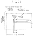
- a picked-up image as shown in FIG. 24 and the image frame of the photographic camera are displayed on the screen of the small-sized CRT of the electronic viewfinder 30.
- the image frame of the photographic camera is displayed at a location corresponding to the zooming power.
- the size of the picked-up image is previously reduced to such an extent that the image frame of the photographic camera at the WIDE end can be displayed when the picked-up image is generated by the video camera at the TELE end.
- the picked-up image is shown at the center of the screen of the small-sized CRT.
- a time base compressing process for such an image reduction is executed, e.g., by an encoder 28.
- the view field of the photographic camera can be accurately recognized even if the zooming power of the video camera or that of the photographic camera is changed. Accordingly, the user can correctly release the shutter of the photographic camera while viewing the display screen of the electronic viewfinder 30.
- this invention can be applied to a video camera to which a separate photographic camera is firmly fixed.
- input means for inputting e.g., data representing the view fields T'PH and T'PV of the photographic camera (or data of the view angles ⁇ PH and ⁇ PV, or data representing the focal length f and the image plane size, PH and PV, of the film used) to the controller 27 may be provided, whereby the invention can be applied to any type of photographic cameras.
- the zoom buttons 5T and 5W are used for changing the zooming power of both the imaging lenses 2 and 3, but separate operating buttons may be provided for the purpose.
Landscapes
- Physics & Mathematics (AREA)
- General Physics & Mathematics (AREA)
- Engineering & Computer Science (AREA)
- Multimedia (AREA)
- Signal Processing (AREA)
- Studio Devices (AREA)
Description
- This invention relates to a video camera having a zoom function and including an electronic viewfinder.
- Using a video camera permits both a still image and a dynamic image to be obtained. Since the resolution of video cameras is lower than that of photographic cameras (film cameras), there is a demand for a combined use of a video camera and a photographic camera. For example, a photographic camera may be firmly fixed to a video camera so that the shutter of the photographic camera can be operated while a dynamic image is recorded by the video camera.
- In the US-A-4,148,072 a camera system is disclosed which includes a photographic camera of the still or motion picture type with an adjustable lens system and a TV camera with a fixed lens system. whereby the object angle of the photographic camera is less than or equal to the object angle of the TV camera. In this system, a circuit is provided to define the variable object field of the photographic camera by a luminous frame on a monitor screen also displaying the fixed object field of the TV camera.
- The JP-A-1-013 530 discloses a visual field expanded type camera for finder wherein the photographic range of a camera having a zoom lens is confirmed in a video picture of a video camera having a fixed focal length.
- In video cameras having a zoom function, the angle of view of a picked-up image changes as the zooming power is changed. This is the case with photographic cameras having a zoom function.
- Accordingly, when operating the shutter of the photographic camera while viewing an electronic viewfinder of the video camera, the field of view of the photographic camera cannot be accurately recognized, and thus the shutter cannot be correctly released.
- An object of this invention is, therefore, to provide a video camera which permits the view field of a photographic camera to be accurately recognized even if the zooming power is changed.
- The invention is defined in appended
claim 1. - According to this invention, the image frame of the photographic camera is displayed at the electronic viewfinder on the basis of a picked-up image of fixed size. Accordingly, the view field of the photographic camera can be accurately recognized, whereby the user can correctly operate the shutter of the photographic camera while viewing the display screen of the electronic viewfinder.
- The objects, advantages and novel features of the present invention will be apparent from the following detailed description when read in conjunction with the appended claims and attached drawings.
-
- FIG. 1 is a perspective view showing an external appearance of an embodiment according to this invention;
- FIG. 2 is a block diagram showing the arrangement of a video camera section;
- FIG. 3 is a schematic diagram showing a color coding of an imaging device;
- FIG. 4 is a diagram showing an output of a horizontal output register of the imaging device;
- FIG. 5 is a diagram illustrating a chrominance signal processing;
- FIG. 6 is a diagram also illustrating the chrominance signal processing;
- FIG. 7 is a schematic diagram showing the arrangement of a zoom driver;
- FIG. 8 is a graph showing the relationship between a zoomed view angle and a detection signal;
- FIG. 9 is a diagram illustrating a procedure for obtaining an angle of view;
- FIG. 10 is a diagram showing an image plane size of a 1/3-inch CCD solid-state imaging device;
- FIG. 11 is a diagram showing an image plane size of a 35 mm film;
- FIG. 12 is a diagram showing fields of view (horizontal direction) of a picked-up image and a photographic camera;
- FIG. 13 is a diagram showing fields of view (vertical direction) of the picked-up image and the photographic camera;
- FIG. 14 is a flowchart showing an image frame data output process;
- FIG. 15 is a diagram showing a display screen of an electronic viewfinder;
- FIG. 16 is a block diagram showing the arrangement of a video camera section;
- FIG. 17 is a schematic diagram showing the arrangement of a zoom driver;
- FIG. 18 is a graph showing the relationship between the zoomed view angle and a detection signal;
- FIG. 19 is a schematic diagram showing the arrangement of a zoom driver;
- FIG. 20 is a graph showing the relationship between the zoomed view angle and a detection signal;
- FIG. 21 is a diagram showing the view fields (horizontal direction) of a picked-up image and a photographic camera;
- FIG. 22 is a diagram showing the view fields (vertical direction) of the picked-up image and the photographic camera;
- FIG. 23 as is a flowchart showing an image frame data output process;
- FIG. 24 is a diagram showing a display screen of an electronic viewfinder;
- One embodiment of this invention will be described with reference to the drawings. The embodiment comprises an integral combination of a video camera and a photographic camera.
- FIG. 1 is a perspective view showing an entire arrangement, wherein
reference numeral 1 denotes a cabinet which has a built-in video camera section including an imaging device, a signal processing circuit, etc., and a built-in photographic camera section including a film loading mechanism, a film drive mechanism, etc., none of which are shown. -
Reference numeral 2 denotes an imaging lens of the video camera section, and 3 denotes an imaging lens of the photographic camera section. The optical system for the video camera section is separate from that for the photographic camera section. A 6-power zoom lens having a focal length f of 7 to 42 mm is used for theimaging lens 2, and a fixed-focus lens having a focal length f of 55 mm is used for theimaging lens 3. - In this embodiment, an electronic viewfinder comprising a small-sized CRT is arranged in the
cabinet 1, for displaying an image picked up by the video camera section through theimaging lens 2.Reference numeral 4 represents an eyecup. There is provided no finder permitting a direct observation of an image to be photographed by the photographic camera section through theimaging lens 3. - Further, 5T and 5W denote zoom buttons for a zooming operation in a TELE direction and a WIDE direction, respectively, 6 denotes a record button for recording a video signal output from the video camera section in a VTR, 7 denotes a shutter button of the photographic camera section, and 8 denotes a film rewind button.
- FIG. 2 is a block diagram showing the arrangement of the video camera section. An image light from an object enters through the
imaging lens 2 and aniris 11 and falls upon a single-plate CCD solid-state imaging device 12 having a complementary checkered color filter. - FIG. 3 is a schematic diagram showing a color coding of the
imaging device 12, and as illustrated, a field readout is carried out. In A field, charges are mixed in pairs, such as a pair of A1 and A2, and in B field, charges are mixed in pairs such as a pair of B1 and B2. For the A field, charges are output in the order of A1, A2, ..., and for the B field in the order of B1, B2, ..., from a horizontal shift register Hreg. - As shown in FIG. 4, the order of charges a, b, ..., is (Cy + G), (Ye + Mg), ... in A1 line, (Cy + Mg), (Ye + G), ... in A2 line, (G + Cy), (Mg + Ye), ... in B1 line, and (Mg + Cy), (G + Ye), ... in B2 line.
- The charges output from the
imaging device 12 in the aforementioned manner are supplied to a CDS circuit (correlation double sampling circuit) 13 and are extracted thereby to obtain an image signal. By using theCDS circuit 13, it is possible to reduce reset noise, as is known in the art. - Timing pulses needed by the
imaging device 12 and theCDS circuit 13 are produced by atiming generator 14. Thetiming generator 14 is supplied with reference clock pulses CK0 at 8 fsc (fsc represents the color subcarrier frequency) from anoscillator 15, as well as horizontal and vertical synchronizing signals HD and VD from a synchronizinggenerator 16. The synchronizinggenerator 16 is supplied with clock pulses CK1 at 4 fsc from thetiming generator 14. - An image signal output from the
CDS circuit 13 is supplied to alevel detecting circuit 17, which outputs a signal to aniris driver 18. Theiris driver 18 automatically controls the aperture of theiris 11. - A process for obtaining a luminance signal Y and a chroma signal (color differential signal) from the image signal output from the
CDS circuit 13 will be explained. - The luminance signal Y is obtained by adding adjacent signals together. Namely, referring to FIG. 4, summation signals are produced in the sequence of a + b, b + c, c + d, d + e, ....
- For example, the A1 line can be approximated as shown in the following equation:

- The A2 line can be approximated as follows:

- The other lines in the A field and the lines in the B field can be approximated in a similar manner.
- The chroma signal is obtained by subjecting adjacent signals to a subtraction.
- For example, the A1 line can be approximated as shown in the following equation:

- The A2 line can be approximated as follows:

- Similarly, for the other lines in the A field and the lines in the B field, a red differential signal R - Y and a blue differential signal -(B - Y) are alternately derived in a line sequential manner.
- Referring again to FIG. 2, the image signal output from the
CDS circuit 13 is supplied to a low-pass filter 20 constituting a luminance processing unit through anAGC circuit 19. The low-pass filter 20 carries out an addition (averaging) of adjacent signals, and accordingly, a luminance signal Y is output therefrom. - The image signal output from the
AGC circuit 19 is supplied to sample holdingcircuits sample holding circuits timing generator 14. - The
sample holding circuit 21 outputs a continuous signal S1 of (Cy + G) or (Cy + Mg) to a subtracter 23 (see B of FIGS. 5 and 6), and thesample holding circuit 22 outputs a continuous signal S2 of (Ye + Mg) or (Ye + G) to the subtracter 23 (see C of FIGS. 5 and 6). - The
subtracter 23 subtracts the signal S1 from the signal S2, whereby a red differential signal R - Y and a blue differential signal -(B - Y) are alternately output therefrom in a line sequential manner (as shown at D in FIGS. 5 and 6). - The color differential signals output from the
subtracter 23 are supplied directly to a fixed terminal b of achangeover switch 24 and a fixed terminal a of achangeover switch 25, and also supplied to a fixed terminal a of thechangeover switch 24 and a fixed terminal b of thechangeover switch 25 via adelay circuit 26 having a delay time corresponding to one horizontal period. - The switching operation of the changeover switches 24 and 25 is controlled by a
controller 27. Specifically, the switches connect to the respective terminals b during a horizontal period in which the red differential signal R - Y is output from thesubtracter 23, and connect to the respective terminals a during a horizontal period in which the blue differential signal -(B - Y) is output. Thecontroller 27 is supplied with the synchronizing signals HD and VD as reference synchronizing signals from the synchronizinggenerator 16, and the clock pulses CK1 from thetiming generator 14. - Since the changeover switches 24 and 25 are operated in the aforementioned manner, a red differential signal R - Y is output from the
changeover switch 24 in each horizontal period and a blue differential signal -(B - Y) is output from thechangeover switch 25 in each horizontal period. - The luminance signal Y output from the low-
pass filter 20 and the color differential signals (R - Y) and -(B - Y) output from the changeover switches 24 and 25 are supplied to anencoder 28. Theencoder 28 is further supplied with a composite synchronizing signal SYNC, a blanking signal BLK, a burst flag signal BF, and a color subcarrier signal SC from the synchronizinggenerator 16. - In the
encoder 28, as is conventionally known, the luminance signal Y is combined with the synchronizing signal SYNC, and the color differential signals are subjected to quadrature two-phase modulation to form a carrier chrominance signal C and further combined with a color burst signal. The luminance signal Y and the carrier chrominance signal C are added together to form, e.g., a color video signal SCV according to the NTSC system. The color video signal SCV thus generated by theencoder 28 appears at anoutput terminal 29. - The
encoder 28 also generates a monochromatic video signal SV (i.e., the luminance signal Y combined with the synchronizing signal SYNC), which is supplied to anelectronic viewfinder 30 through anadder 31. Thus, a picked-up image is displayed at the small-sized CRT constituting theelectronic viewfinder 30. - The zooming power of the
imaging lens 2 is adjusted by azoom driver 41. FIG. 7 shows in detail the arrangement of thezoom driver 41, whereinreference numeral 411 denotes a lens constituting theimaging lens 2 for adjusting the zooming power. Thelens 411 can be moved back and forth when rotated, whereby the zooming power is adjusted. For example, if thelens 411 is rotated in a direction T, the zooming power changes in the TELE direction; if the lens is rotated in a direction W, then the zooming power changes in the WIDE direction. - The
lens 411 is rotated by aDC motor 412, which is connected to output terminals q1 and q2 of azoom driver unit 413. Input terminals p1 and p2 of thezoom driver unit 413 are respectively connected to fixed terminals T and W of azoom switch 42. - In this arrangement, when a high-level "H" signal is supplied to the terminal p1, a current flows through the
motor 412 from the terminal q1 to the terminal q2 (as indicated by the solid line), and thelens 411 is rotated in the direction T. On the other hand, when a high-level "H" signal is supplied to the terminal p2, a current flows through themotor 412 from the terminal q2 to the terminal q1 (as indicated by the dashed arrow), and thelens 411 is rotated in the direction W. When neither the terminal p1 nor the terminal p2 is supplied with a high-level "H" signal, no current flows through themotor 412, and accordingly, thelens 411 is not rotated in either direction and the position thereof remains unchanged. - A movable terminal of the
zoom switch 42 is connected to a power supply terminal. When theoperating button aforementioned cabinet 1 is pressed, thezoom switch 42 is connected to the terminal T or W, and a high-level "H" signal is supplied to the terminal p1 or p2 of thezoom driver unit 413, whereby the zooming power is adjusted in the TELE or WIDE direction. - Further, as shown in FIG. 2, a
variable resistor 44 constituting a potentiometer is arranged at a location where thelens 411 of theimaging lens 2 is mounted. Thevariable resistor 44 is constructed such that the position of a movable terminal thereof is shifted with a rotation of thelens 411, whereby a voltage corresponding to the zooming power builds up at the movable terminal and is applied to thecontroller 27 as a detection signal SD. As shown in FIG. 8, the detection signal SD is set such that it is 1 V at the WIDE end (f = 7 mm) and 4 V at the TELE end (f = 42 mm). - In this embodiment, a picked-up image is displayed at a fixed position on the screen of the small-sized CRT of the
electronic viewfinder 30, and at the same time an image frame of the photographic camera is displayed on the same screen. The angle of view of a picked-up image changes in accordance with the zooming power, and thus the view field thereof changes accordingly. To display an image frame of the photographic camera on the screen of the small-sized CRT, the ratio of the view fields of the photographic camera and the picked-up image must be obtained. - Here, the angle of view will be explained with reference to FIG. 9. The angle of view, θ, can be obtained from an image plane size T and the value f (focal length), as shown in equation (1) below. In FIG. 9, T' denotes the view field, and L denotes the distance to an object.

- The
imaging lens 2 is a 6-power zoom lens having a focal length f of 7 to 42 mm, and where theimaging device 12 is a 1/3-inch type, the image plane having a horizontal size ZH of 4.9 mm, a vertical size ZV of 3.69 mm, and a diagonal size ZD of 6.13 mm (see FIG. 10). - Therefore, angles θZH, θZV and θZD of view in the horizontal, vertical and diagonal directions at the WIDE end (f = 7 mm) are 38.6°, 29.5°, and 47.3°, respectively, and angles θZH, θZV and θZD of view in the horizontal, vertical and diagonal directions at the TELE end (f = 42 mm) are 6.7°, 5.0°, and 8.3°, respectively.
- The
imaging lens 3 is a fixed-focus lens having a focal length f of 55 mm, and where the film used is a 35 mm type, the image plane having a horizontal size PH of 36 mm, a vertical size PV of 24 mm, and a diagonal size PD of 43.3 mm (see FIG. 11). - Therefore, angles θPH, θPV and θPD of view in the horizontal, vertical and diagonal directions are 36.2°, 24.6°, and 43.0°, respectively.
- From the above, the relationship between the angles of view of the
imaging lens 2, which is a zoom lens, and the angles of view of theimaging lens 3, which is a fixed-focus lens, can be summarized as shown in Table 1 below.TABLE 1 Picked-up image WIDE - TELE Photographic camera Horizontal direction θZH = 38.6 to 6.7° θPH = 36.2° Vertical direction θZV = 29.5 to 5.0° θPV = 24.6° Diagonal direction θZD = 47.3 to 8.3° θPD = 43.0° - The ratio of the view fields of the photographic camera and picked-up image will be now explained. From FIG. 9, the view field T' is given by the following equation (2):

- Provided that the distances L from an object to both the
imaging lenses - From the horizontal and vertical view angles θZH and θZV of the picked-up image shown in Table 1, view fields T'ZH and T'ZV in the horizontal and vertical directions at the WIDE end are 0.7L and 0.53L, respectively, and view fields T'ZH and T'ZV in the horizontal and vertical directions at the TELE end are 0.12L and 0.09L, respectively.
- View angles θZH and θZV of the picked-up image at any point between the WIDE and TELE ends can be obtained from the detection signal SD, using the following equations (3):


- By substituting the view angles θZH and θZV obtained by equations (3) individually for θ in equation (2), the view fields T'ZH and T'ZV can be obtained.
- From the horizontal and vertical view angles θPH and θPV of the photographic camera shown in Table 1, view fields T'PH and T'PV in the horizontal and vertical directions are 0.65L and 0.44L, respectively.
- Based on the foregoing, the relationship between the view fields of the picked-up image and those of the photographic camera can be summarized as shown in Table 2 below. FIG. 12 shows the relationship of the horizontal view fields, and FIG. 13 shows the relationship of the vertical view fields.
TABLE 2 Picked-up image WIDE - TELE Photographic camera Horizontal direction T'ZH = 0.7L to 0.12L T'PH = 0.65L Vertical direction T'ZV = 0.53L to 0.09L T'PV = 0.44L - Table 3 shows view field ratios T'PH/T'ZH and T'PV/T'ZV in the horizontal and vertical directions, respectively.
TABLE 3 Picked-up image WIDE - TELE View field ratio T'PH/T'ZH in horizontal direction 0.93 to 5.42 View field ratio T'PV/T'ZV in vertical direction 0.83 to 4.89 - From FIG. 9, the view field T' can also be obtained as shown in equation (4).

- The focal length f can be obtained from the detection signal SD, using the following equation (5):

- The focal length f, obtained by equation (5), is substituted into equation (4) and the horizontal and vertical sizes ZH and ZV of the image plane are substituted individually for T in equation (4), whereby the horizontal and vertical view fields T'ZH and T'ZV are obtained.
- Referring again to FIG. 2, the
controller 27 generates image frame data Dm for displaying the image frame of the photographic camera at a position corresponding to the horizontal and vertical view field ratios T'PH/T'ZH and T'PV/T'ZV. - FIG. 14 is a flowchart showing an image frame data output process executed by the
controller 27. First, the focal length f is computed from the detection signal SD, using equation (5) (Step 51). - Subsequently, the focal length f is substituted into equation (4), and the horizontal and vertical sizes ZH and ZV of the image plane are substituted individually for T in equation (4), to thereby obtain horizontal and vertical view fields T'ZH and T'ZV of the picked-up image (Step 52).
- Then, using the view fields T'ZH and T'ZV, ratios T'PH/T'ZH and T'PV/T'ZV of the view field of the photographic camera to that of the picked-up image in the horizontal and vertical directions are calculated (Step 53).
- Next, image frame data Dm corresponding to the view field ratios T'PH/T'ZH and T'PV/T'ZV is output (Step 54). The image frame data Dm is used, e.g., for an image frame signal to indicate horizontal and vertical positions. In this case, the image frame data Dm is generated based on the horizontal and vertical display lengths of a picked-up image of fixed size such that the horizontal and vertical lengths of the image frame are substantially equal to the corresponding lengths specified by the view field ratios T'PH/T'ZH and T'PV/T'ZV. The horizontal length of the image frame is adjusted in units of pixel pitch, and the vertical length of the same is adjusted in units of line pitch.
- The image frame data Dm output from the
controller 27 is supplied to a framesignal generating circuit 32. The framesignal generating circuit 32 is also supplied with the synchronizing signals HD and VD from the synchronizinggenerator 16, and the clock pulses CK1 from thetiming generator 14. The framesignal generating circuit 32 outputs, e.g., a white peak level signal at times corresponding to the horizontal and vertical positions specified by the image frame data Dm, and this signal is supplied to theadder 31 as a frame signal Sm to be added to the monochromatic video signal SV. - Accordingly, a picked-up image as shown in FIG. 15 and the image frame of the photographic camera are displayed on the screen of the small-sized CRT of the
electronic viewfinder 30. In this case, while the size of the picked-up image is fixed, the image frame of the photographic camera is displayed at a location corresponding to the zooming power. - The size of the picked-up image is previously reduced to such an extent that the image frame of the photographic camera at the TELE end can be displayed, and the picked-up image is shown at the center of the screen of the small-sized CRT. A time base compressing process for such an image reduction is executed, e.g., by the
encoder 28. - In this embodiment, since the image frame of the photographic camera is displayed on the screen of the small-sized CRT of the
electronic viewfinder 30 on the basis of the picked-up image of fixed size, the view field of the photographic camera can be accurately recognized even if the zooming power is changed. Accordingly, the user can correctly release the shutter of the photographic camera while viewing the display screen of theelectronic viewfinder 30. - Although, in this embodiment, the video camera and the photographic camera are integrally combined, this invention can be applied to a video camera to which a separate photographic camera is firmly fixed. In this case, input means for inputting, e.g., data representing the view fields T'PH and T'PV of the photographic camera (or data of the view angles θPH and θPV, or data representing the focal length f and the image plane size, PH and PV, of the film used) to the
controller 27 may be provided, whereby the invention can be applied to any type of photographic cameras. - A further embodiment of this invention will be described with reference to the drawings. FIG. 16 is a block diagram showing the arrangement of a video camera section according to this embodiment. In FIG. 16, the same reference numerals are used to denote corresponding parts in FIG. 2, and a detailed description thereof is omitted.
- As shown in FIG. 16, a monochromatic video signal SV output from an
encoder 28 is supplied to anelectronic viewfinder 30 through anadder 31, and a picked-up image is displayed at a small-sized CRT constituting theelectronic viewfinder 30. - A
zoom driver 41 in FIG. 16 has an arrangement shown in FIG. 17. In the figure,reference numeral 411 represents a lens which constitutes animaging lens 2 and is used to adjust the zooming power. Thelens 411 can be moved back and forth when rotated, whereby the zooming power is adjusted. For example, when thelens 411 is rotated in a direction T, the zooming power changes in the TELE direction; when the lens is rotated in a direction W, the zooming power changes in the WIDE direction. - The
lens 411 is rotated by aDC motor 412, which is connected to output terminals q1 and q2 of azoom driver unit 413. Input terminals p1 and p2 of thezoom driver unit 413 are connected, respectively, to fixed terminals T and W of azoom switch 42 through terminals v of respective changeover switches 45 and 46. - The switching of the changeover switches 45 and 46 is carried out by a zoom selection button (not shown in FIG. 1) arranged in the
cabinet 1. For example, when the zoom selection button is not pressed, theswitches - When a high-level "H" signal is supplied to the terminal pl of the
zoom driver unit 413, a current flows through themotor 412 from the terminal ql to the terminal q2 (as indicated by the solid line), and thelens 411 is rotated in the direction T. On the other hand, when a high-level "H" signal is supplied to the terminal p2, a current flows through themotor 412 from the terminal q2 to the terminal q1 (as indicated by the dashed arrow), and thelens 411 is rotated in the direction W. When neither the terminal p1 nor p2 is supplied with a high-level "H" signal, no current flows through themotor 412, and therefore, thelens 411 is not rotated in either direction and the position thereof is maintained. - A movable terminal of the
zoom switch 42 is connected to a power supply terminal. When theoperating button cabinet 1 is pressed, thezoom switch 42 is connected to the terminal T or W. When theoperating button zoom driver unit 413, whereby the zooming power is adjusted in the TELE or WIDE direction. - As shown in FIG. 16, a
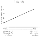
variable resistor 44 constituting a potentiometer is arranged at a location where thelens 411 of theimaging lens 2 is mounted. Thevariable resistor 44 is constructed such that the position of a movable terminal thereof is shifted as thelens 411 is rotated, whereby a voltage corresponding to the zooming power appears at the movable terminal and is applied to thecontroller 27 as a detection signal SDv. As shown in FIG. 18, the detection signal SDv is set such that it is 1 V at the WIDE end (f = 7 mm) and 4 V at the TELE end (f = 42 mm). - In this embodiment, a 3-power zoom lens having a focal length f of 35 to 105 mm is used for the
imaging lens 3 of the photographic camera section, and the zooming power of theimaging lens 3 is adjusted by azoom driver 47. FIG. 19 shows the arrangement of thezoom driver 47 in detail. Thiszoom driver 47 has an arrangement similar to that of theaforementioned zoom driver 41, and therefore, the same reference numerals are used to represent corresponding parts and a detailed description thereof is omitted. - Input terminals p1 and p2 of a
zoom driver unit 413 of thezoom driver 47 are connected to fixed terminals T and W of azoom switch 42 through terminals p of changeover switches 45 and 46, respectively. - When the
operating button cabinet 1 is pressed, thezoom switch 42 is connected to the terminal T or W. When theoperating button zoom driver unit 413, whereby the zooming power is adjusted in the TELE or WIDE direction. - As shown in FIG. 16, a
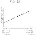
variable resistor 48 constituting a potentiometer is arranged at a location where thelens 411 of theimaging lens 3 is mounted. Thevariable resistor 48 is constructed such that the position of a movable terminal thereof is shifted as thelens 411 is rotated, whereby a voltage corresponding to the zooming power appears at the movable terminal and is applied to thecontroller 27 as a detection signal SDp. As shown in FIG. 20, the detection signal SDp is set such that it is 1 V at the WIDE end (f = 35 mm) and 4 V at the TELE end (f = 105 mm). - In this embodiment, a picked-up image is displayed at a fixed position on the screen of the small-sized CRT of the
electronic viewfinder 30, and at the same time, an image frame of the photographic camera is displayed on the same screen. The angles of view of the video camera and the photographic camera change in accordance with the zooming power, and thus the view fields thereof change accordingly. To display an image frame of the photographic camera on the screen of the small-sized CRT, the ratio of the view fields of the picked-up image and the photographic camera must be obtained. - The view angle θ can be obtained from the image plane size T and the value f (focal length), using the above equation (1) and based on FIG. 9.
- The
imaging lens 2 is a 6-power zoom lens having an f value of 7 to 42 mm. In the case wherein theimaging device 12 is a 1/3-inch·type, the image plane has a horizontal size ZH of 4.9 mm, a vertical size ZV of 3.69 mm, and a diagonal size ZD of 6.13 mm (see FIG. 10). - Therefore, the view angles θZH and θZV in the horizontal and vertical directions at the WIDE end (f = 7 mm) are 38.6° and 29.5°, respectively. The view angles θZH and θZV in the horizontal and vertical directions at the TELE end (f = 42 mm) are 6.7° and 5.0°, respectively.
- The
imaging lens 3 is a 3-power zoom lens having an f value of 35 to 105 mm. Where the film used is a 35 mm type, the image plane has a horizontal size PH of 36 mm, a vertical size PV of 24 mm, and a diagonal size PD of 43.3 mm (see FIG. 11). - Therefore, the view angles θPH and θPV in the horizontal and vertical directions at the WIDE end (f = 35 mm) are 54.4° and 37.8°, respectively, and the view angles θPH and θPV in the horizontal and vertical directions at the TELE end (f = 105 mm) are 19,5° and 13.0°, respectively.
- From the above, the relationship between the view angles of the
imaging lenses TABLE 5 Picked-up image WIDE - TELE Photographic camera WIDE - TELE Horizontal direction θ ZH = 38.6 to 6.7° θ PH = 54.4 to 19.5° Vertical direction θ ZV = 29.5 to 5.0° θ PV = 37.8 to 13.0° - The ratio of the view fields of the photographic camera and the picked-up image will be now explained. From FIG. 9, the view field T' can be obtained by the aforementioned equation (2).
- Provided that the distances L from the object to both the
imaging lenses - From the horizontal and vertical view angles θZH and θZV of the picked-up image shown in Table 5, view fields T'ZH and T'ZV in the horizontal and vertical directions at the WIDE end are 0.7L and 0.53L, respectively, and view fields T'ZH and T'ZV in the horizontal and vertical directions at the TELE end are 0.12L and 0.09L, respectively.
- View angles θZH and θZV of the picked-up image at any point between the WIDE and TELE ends can be obtained from the detection signal SDv, using the following equations (6):


- By substituting the view angles θZH and θZV obtained by equations (6) individually for θ in equation (2), the view fields T'ZH and T'ZV can be obtained.
- From the horizontal and vertical view angles θPH and θPV of the photographic camera shown in Table 5, view fields T'PH and T'PV in the horizontal and vertical directions at the WIDE end are 1.03L and 0.69L, respectively, and view fields T'PH and T'PV in the horizontal and vertical directions at the TELE end are 0.34L and 0.23L, respectively.
- View angles θPH and θPV of the photographic camera at any point between the WIDE and TELE ends can be obtained from the detection signal SDp, using the following equations (7):


- By substituting the view angles θPH and θPV obtained by equations (7) individually for 9 in equation (2), the view fields T'PH and T'PV can be obtained.
- From the foregoing, the relationship between the view field of the picked-up image and that of the photographic camera can be summarized as shown in Table 6 below. FIG. 21 shows the relationship of the view fields in the horizontal direction, and FIG. 22 shows the relationship of the view fields in the vertical direction.
TABLE 6 Picked-up image WIDE - TELE Photographic camera WIDE - TELE Horizontal direction T'ZH = 0.7L to 0.12L T'PH = 1.03L to 0.34L Vertical direction T'ZV = 0.53L to 0.09L T'PV = 0.69L to 0.23L - Further, view field ratios T'PH/T'ZH and T'PV/T'ZV in the horizontal and vertical directions become as shown in Table 7.
TABLE 7 View field ratio T'PH/T'ZH in horizontal direction 0.49 to 8.58 View field ratio T'PV/T'ZV in vertical direction 0.43 to 7.67 - From FIG. 9, the view field T' can also be obtained as shown in the aforementioned equation (4).
- The focal length f of the
imaging lens 2 can be obtained from the detection signal SDv, using the following equation (8):
- The focal length f, obtained by equation (8), is substituted into equation (4) and the horizontal and vertical sizes ZH and ZV of the image plane are substituted individually for T in equation (4), whereby the horizontal and vertical view fields T'ZH and T'ZV are obtained.
- The focal length f of the
imaging lens 3 can be obtained from the detection signal SDp, using the following equation (9):
- By substituting the focal length f obtained by equation (9) into equation (4) and substituting the horizontal and vertical sizes PH and PV of the image plane individually for T in equation (4), the horizontal and vertical view fields T'PH and T'PV can be obtained.
- Referring again to FIG. 16, the
controller 27 generates image frame data Dm for displaying the image frame of the photographic camera at a location on the display screen corresponding to the horizontal and vertical view field ratios T'PH/T'ZH and T'PV/T'ZV. - FIG. 23 is a flowchart showing an image frame data output process executed by the
controller 27. First, the focal length f of theimaging lens 2 is computed from the detection signal SDv, using equation (8) (Step 71). - Subsequently, the obtained focal length f is substituted into equation (4), and the horizontal and vertical sizes ZH and ZV of the image plane are substituted individually for T in equation (4), to thereby obtain horizontal and vertical view fields T'ZH and T'ZV of the video camera (Step 72).
- The focal length f of the
imaging lens 3 is then calculated from the detection signal SDp, using equation (9) (Step 73). - Next, the thus-obtained focal length f is substituted into equation (4), and the horizontal and vertical sizes PH and PV of the image plane are substituted individually for T in equation (4), to thereby obtain horizontal and vertical view fields T'PH and T'PV of the photographic camera (Step 74).
- Then, using the view fields T'ZH, T'ZV, T'PH and T'PV, ratios T'PH/T'ZH and T'PV/T'ZV of the view field of the photographic camera to that of the picked-up image in the horizontal and vertical directions are calculated (Step 75).
- Next, image frame data Dm corresponding to the view field ratios T'PH/T'ZH and T'PV/T'ZV is output (Step 76). The image frame data Dm is used. e.g., for an image frame signal to indicate horizontal and vertical positions. In this case, the image frame data Dm is generated based on the horizontal and vertical display lengths of a picked-up image of fixed size such that the horizontal and vertical lengths of the image frame are substantially equal to the corresponding lengths determined by the view field ratios T'PH/T'ZH and T'PV/T'ZV. The horizontal length of the image frame is adjusted in units of pixel pitch, and the vertical length of same is adjusted in units of line pitch.
- Referring again to FIG. 16, the image frame data Dm output from the
controller 27 is supplied to a framesignal generating circuit 32. The framesignal generating circuit 32 is also supplied with synchronizing signals HD and VD from the synchronizinggenerator 16, and clock pulses CK1 from thetiming generator 14. The framesignal generating circuit 32 outputs, e.g., a white peak level signal at times corresponding to the horizontal and vertical positions specified by the image frame data Dm, and this signal is supplied to anadder 31 as a frame signal Sm to be added to a monochromatic video signal SV. - Accordingly, a picked-up image as shown in FIG. 24 and the image frame of the photographic camera are displayed on the screen of the small-sized CRT of the
electronic viewfinder 30. In this case, while the size of the picked-up image is fixed, the image frame of the photographic camera is displayed at a location corresponding to the zooming power. - The size of the picked-up image is previously reduced to such an extent that the image frame of the photographic camera at the WIDE end can be displayed when the picked-up image is generated by the video camera at the TELE end. The picked-up image is shown at the center of the screen of the small-sized CRT. A time base compressing process for such an image reduction is executed, e.g., by an
encoder 28. - In this embodiment, since the image frame of the photographic camera is displayed on the screen of the small-sized CRT of the
electronic viewfinder 30 on the basis of the picked-up image of fixed size, the view field of the photographic camera can be accurately recognized even if the zooming power of the video camera or that of the photographic camera is changed. Accordingly, the user can correctly release the shutter of the photographic camera while viewing the display screen of theelectronic viewfinder 30. - Although, in this embodiment, the video camera and the photographic camera are integrally combined, this invention can be applied to a video camera to which a separate photographic camera is firmly fixed. In this case, input means for inputting, e.g., data representing the view fields T'PH and T'PV of the photographic camera (or data of the view angles θPH and θPV, or data representing the focal length f and the image plane size, PH and PV, of the film used) to the
controller 27 may be provided, whereby the invention can be applied to any type of photographic cameras. - Further, in the above embodiment, the
zoom buttons imaging lenses - It will be obvious to those having ordinary skill in the art that many changes may be made in the above-described details of the preferred embodiments of the present invention without departing from the scope of the present invention.
Claims (1)
- A video camera for use with a photographic camera, said video camera comprising:an electronic viewfinder (30) for providing image information of said video camera and of a photographic camera;video pickup means (2, 11) for picking-up a video image;video signal generating means (12) for generating an image video signal representative of said picked-up video image;image frame signal generating means (32) for generating an image frame signal representative of an image frame of the field of view of the photographic camera;image frame position changing means (27) for affecting the image frame signal generating means to generate said image frame signal so as to change said image frame representing the field of view of the photographic camera; andsignal composition means (31) for providing a composite signal for driving the electronic viewfinder (30) by combining the image video signal with the image frame signal;wherein the picked-up video image is displayed with a fixed size on the screen of the electronic viewfinder (30), and the image frame of the photographic camera is displayed on the screen relative to the picked-up video image in accordance with the view field ratio of the photographic camera with respect to the video camera,characterized in thatthe video camera has a zoom function affecting the field of view of said video camera in accordance with an adjustable zoom power, wherebysaid video pickup means picking up the video image within the field of view determined by said zoom power; and wherebysaid image frame of the photographic camera being changed in accordance with the field of view of the video camera that is calculated based on information about said zoom power of the video camera, and in thatsaid fixed size of the picked-up video image is reduced to such an extent that it covers only a portion of the view finder screen so that the image frame of the photographic camera can always be displayed on said screen, even when the picked-up image is generated by said video camera at the TELE end.
Applications Claiming Priority (16)
| Application Number | Priority Date | Filing Date | Title |
|---|---|---|---|
| JP3138012A JP3048408B2 (en) | 1991-06-10 | 1991-06-10 | Video camera |
| JP138012/91 | 1991-06-10 | ||
| JP139207/91 | 1991-06-11 | ||
| JP139160/91 | 1991-06-11 | ||
| JP3139172A JP3048410B2 (en) | 1991-06-11 | 1991-06-11 | Video camera |
| JP3139160A JP3048409B2 (en) | 1991-06-11 | 1991-06-11 | Video camera |
| JP139181/91 | 1991-06-11 | ||
| JP139172/91 | 1991-06-11 | ||
| JP3139181A JP3048411B2 (en) | 1991-06-11 | 1991-06-11 | Video camera |
| JP3139207A JP3048412B2 (en) | 1991-06-11 | 1991-06-11 | Video camera |
| JP142143/91 | 1991-06-13 | ||
| JP3142143A JPH05110916A (en) | 1991-06-13 | 1991-06-13 | Video camera |
| JP3218548A JP3043854B2 (en) | 1991-08-29 | 1991-08-29 | Camera device |
| JP218549/91 | 1991-08-29 | ||
| JP218548/91 | 1991-08-29 | ||
| JP3218549A JP3043855B2 (en) | 1991-08-29 | 1991-08-29 | Camera device |
Publications (2)
| Publication Number | Publication Date |
|---|---|
| EP0518286A1 EP0518286A1 (en) | 1992-12-16 |
| EP0518286B1 true EP0518286B1 (en) | 1997-12-29 |
Family
ID=27573163
Family Applications (1)
| Application Number | Title | Priority Date | Filing Date |
|---|---|---|---|
| EP92109736A Expired - Lifetime EP0518286B1 (en) | 1991-06-10 | 1992-06-10 | Video camera for camera system |
Country Status (4)
| Country | Link |
|---|---|
| US (1) | US5398062A (en) |
| EP (1) | EP0518286B1 (en) |
| CA (1) | CA2070764A1 (en) |
| DE (1) | DE69223689T2 (en) |
Families Citing this family (8)
| Publication number | Priority date | Publication date | Assignee | Title |
|---|---|---|---|---|
| US5706049A (en) * | 1995-11-30 | 1998-01-06 | Eastman Kodak Company | Camera that records an active image area identifier with an image |
| US5926218A (en) * | 1996-06-04 | 1999-07-20 | Eastman Kodak Company | Electronic camera with dual resolution sensors |
| US5822625A (en) * | 1997-02-19 | 1998-10-13 | Eastman Kodak Company | Hybrid electronic-film camera |
| US5787313A (en) * | 1997-02-20 | 1998-07-28 | Eastman Kodak Company | Hybrid camera including viewfinder with masks for parallax correction and image format indication |
| US5974272A (en) * | 1997-10-29 | 1999-10-26 | Eastman Kodak Company | Parallax corrected image capture system |
| US8004572B2 (en) * | 1999-05-17 | 2011-08-23 | Zin Stai Pte. In, Llc | System for transmitting a video stream over a computer network to a remote receiver |
| KR100826243B1 (en) * | 2002-11-20 | 2008-04-29 | 삼성전자주식회사 | Shooting device capable of adjusting the angle of view and control method thereof |
| JP4730569B2 (en) * | 2009-03-27 | 2011-07-20 | カシオ計算機株式会社 | Imaging apparatus, imaging method, and program |
Family Cites Families (6)
| Publication number | Priority date | Publication date | Assignee | Title |
|---|---|---|---|---|
| AT358636B (en) * | 1975-05-02 | 1980-02-15 | Eumig | ARRANGEMENT WITH A PHOTOGRAPHIC OR KINEMATOGRAPHIC CAMERA AND A TELEVISION CAMERA |
| US4432014A (en) * | 1981-05-08 | 1984-02-14 | General Electric Company | Video-photo frame size coordinator |
| US4527201A (en) * | 1983-03-29 | 1985-07-02 | Panavision, Inc. | Zoom indicating apparatus for video camera or the like |
| SE461619B (en) * | 1988-07-06 | 1990-03-05 | Hasselblad Ab Victor | DEVICE FOR CAMERAS CONCERNING A COMPOSITION OF A PHOTOCHEMICAL AND ELECTRONIC CAMERA |
| US5161025A (en) * | 1989-12-28 | 1992-11-03 | Fuji Photo Film Co., Ltd. | Optical/electrical view finder |
| JPH04139970A (en) * | 1990-09-29 | 1992-05-13 | Sony Corp | Picture display device |
-
1992
- 1992-06-09 US US07/896,059 patent/US5398062A/en not_active Expired - Lifetime
- 1992-06-09 CA CA002070764A patent/CA2070764A1/en not_active Abandoned
- 1992-06-10 DE DE69223689T patent/DE69223689T2/en not_active Expired - Fee Related
- 1992-06-10 EP EP92109736A patent/EP0518286B1/en not_active Expired - Lifetime
Also Published As
| Publication number | Publication date |
|---|---|
| US5398062A (en) | 1995-03-14 |
| CA2070764A1 (en) | 1992-12-11 |
| EP0518286A1 (en) | 1992-12-16 |
| DE69223689T2 (en) | 1998-07-23 |
| DE69223689D1 (en) | 1998-02-05 |
Similar Documents
| Publication | Publication Date | Title |
|---|---|---|
| US8155432B2 (en) | Photographing apparatus | |
| US20050088546A1 (en) | Photographic apparatus | |
| AU708333B2 (en) | Lens driving device and image pick-up apparatus employing this lens driving device | |
| US20110018971A1 (en) | Compound-eye imaging apparatus | |
| US5398062A (en) | Video camera and camera system having an electronic viewfinder portraying image information | |
| EP0709753B1 (en) | A camera apparatus comprising a video camera and a photographic camera | |
| JP4013026B2 (en) | Electronic camera and image display method during automatic focus adjustment | |
| JP2607536Y2 (en) | Camera viewfinder display | |
| JP3048411B2 (en) | Video camera | |
| JP3048408B2 (en) | Video camera | |
| JP3048410B2 (en) | Video camera | |
| JP3043855B2 (en) | Camera device | |
| JP3043854B2 (en) | Camera device | |
| JP3048412B2 (en) | Video camera | |
| JP3048409B2 (en) | Video camera | |
| JP3043834B2 (en) | Video camera | |
| JP3928223B2 (en) | Image display device | |
| JP3556742B2 (en) | Video camera equipment | |
| JPH05110915A (en) | Video camera | |
| JP3115653B2 (en) | Photo camera | |
| JP3329475B2 (en) | Video camera | |
| JPH0937142A (en) | Imaging device | |
| JPH11220752A (en) | Video camera | |
| JPH089981Y2 (en) | Video camera | |
| JPH0741260Y2 (en) | Television camera |
Legal Events
| Date | Code | Title | Description |
|---|---|---|---|
| PUAI | Public reference made under article 153(3) epc to a published international application that has entered the european phase |
Free format text: ORIGINAL CODE: 0009012 |
|
| AK | Designated contracting states |
Kind code of ref document: A1 Designated state(s): BE DE FR GB IT NL |
|
| 17P | Request for examination filed |
Effective date: 19930616 |
|
| 17Q | First examination report despatched |
Effective date: 19951107 |
|
| GRAG | Despatch of communication of intention to grant |
Free format text: ORIGINAL CODE: EPIDOS AGRA |
|
| GRAG | Despatch of communication of intention to grant |
Free format text: ORIGINAL CODE: EPIDOS AGRA |
|
| GRAH | Despatch of communication of intention to grant a patent |
Free format text: ORIGINAL CODE: EPIDOS IGRA |
|
| GRAH | Despatch of communication of intention to grant a patent |
Free format text: ORIGINAL CODE: EPIDOS IGRA |
|
| GRAA | (expected) grant |
Free format text: ORIGINAL CODE: 0009210 |
|
| AK | Designated contracting states |
Kind code of ref document: B1 Designated state(s): BE DE FR GB IT NL |
|
| PG25 | Lapsed in a contracting state [announced via postgrant information from national office to epo] |
Ref country code: BE Free format text: LAPSE BECAUSE OF FAILURE TO SUBMIT A TRANSLATION OF THE DESCRIPTION OR TO PAY THE FEE WITHIN THE PRESCRIBED TIME-LIMIT Effective date: 19971229 |
|
| REF | Corresponds to: |
Ref document number: 69223689 Country of ref document: DE Date of ref document: 19980205 |
|
| ITF | It: translation for a ep patent filed | ||
| ET | Fr: translation filed | ||
| PLBE | No opposition filed within time limit |
Free format text: ORIGINAL CODE: 0009261 |
|
| STAA | Information on the status of an ep patent application or granted ep patent |
Free format text: STATUS: NO OPPOSITION FILED WITHIN TIME LIMIT |
|
| 26N | No opposition filed | ||
| PGFP | Annual fee paid to national office [announced via postgrant information from national office to epo] |
Ref country code: NL Payment date: 20010626 Year of fee payment: 10 |
|
| REG | Reference to a national code |
Ref country code: GB Ref legal event code: IF02 |
|
| PG25 | Lapsed in a contracting state [announced via postgrant information from national office to epo] |
Ref country code: NL Free format text: LAPSE BECAUSE OF NON-PAYMENT OF DUE FEES Effective date: 20030101 |
|
| NLV4 | Nl: lapsed or anulled due to non-payment of the annual fee |
Effective date: 20030101 |
|
| PG25 | Lapsed in a contracting state [announced via postgrant information from national office to epo] |
Ref country code: IT Free format text: LAPSE BECAUSE OF NON-PAYMENT OF DUE FEES Effective date: 20050610 |
|
| PGFP | Annual fee paid to national office [announced via postgrant information from national office to epo] |
Ref country code: DE Payment date: 20070607 Year of fee payment: 16 |
|
| PGFP | Annual fee paid to national office [announced via postgrant information from national office to epo] |
Ref country code: GB Payment date: 20070606 Year of fee payment: 16 |
|
| PGFP | Annual fee paid to national office [announced via postgrant information from national office to epo] |
Ref country code: FR Payment date: 20070608 Year of fee payment: 16 |
|
| GBPC | Gb: european patent ceased through non-payment of renewal fee |
Effective date: 20080610 |
|
| REG | Reference to a national code |
Ref country code: FR Ref legal event code: ST Effective date: 20090228 |
|
| PG25 | Lapsed in a contracting state [announced via postgrant information from national office to epo] |
Ref country code: DE Free format text: LAPSE BECAUSE OF NON-PAYMENT OF DUE FEES Effective date: 20090101 |
|
| PG25 | Lapsed in a contracting state [announced via postgrant information from national office to epo] |
Ref country code: GB Free format text: LAPSE BECAUSE OF NON-PAYMENT OF DUE FEES Effective date: 20080610 |
|
| PG25 | Lapsed in a contracting state [announced via postgrant information from national office to epo] |
Ref country code: FR Free format text: LAPSE BECAUSE OF NON-PAYMENT OF DUE FEES Effective date: 20080630 |