EP0518281B1 - Stirring device - Google Patents
Stirring device Download PDFInfo
- Publication number
- EP0518281B1 EP0518281B1 EP92109730A EP92109730A EP0518281B1 EP 0518281 B1 EP0518281 B1 EP 0518281B1 EP 92109730 A EP92109730 A EP 92109730A EP 92109730 A EP92109730 A EP 92109730A EP 0518281 B1 EP0518281 B1 EP 0518281B1
- Authority
- EP
- European Patent Office
- Prior art keywords
- stirring
- vibration
- attached
- stirring device
- weight
- Prior art date
- Legal status (The legal status is an assumption and is not a legal conclusion. Google has not performed a legal analysis and makes no representation as to the accuracy of the status listed.)
- Expired - Lifetime
Links
Images


Classifications
-
- B—PERFORMING OPERATIONS; TRANSPORTING
- B01—PHYSICAL OR CHEMICAL PROCESSES OR APPARATUS IN GENERAL
- B01F—MIXING, e.g. DISSOLVING, EMULSIFYING OR DISPERSING
- B01F31/00—Mixers with shaking, oscillating, or vibrating mechanisms
- B01F31/44—Mixers with shaking, oscillating, or vibrating mechanisms with stirrers performing an oscillatory, vibratory or shaking movement
- B01F31/445—Mixers with shaking, oscillating, or vibrating mechanisms with stirrers performing an oscillatory, vibratory or shaking movement performing an oscillatory movement about an axis
-
- B—PERFORMING OPERATIONS; TRANSPORTING
- B01—PHYSICAL OR CHEMICAL PROCESSES OR APPARATUS IN GENERAL
- B01F—MIXING, e.g. DISSOLVING, EMULSIFYING OR DISPERSING
- B01F2101/00—Mixing characterised by the nature of the mixed materials or by the application field
- B01F2101/23—Mixing of laboratory samples e.g. in preparation of analysing or testing properties of materials
-
- G—PHYSICS
- G01—MEASURING; TESTING
- G01N—INVESTIGATING OR ANALYSING MATERIALS BY DETERMINING THEIR CHEMICAL OR PHYSICAL PROPERTIES
- G01N35/00—Automatic analysis not limited to methods or materials provided for in any single one of groups G01N1/00 - G01N33/00; Handling materials therefor
- G01N2035/00465—Separating and mixing arrangements
- G01N2035/00534—Mixing by a special element, e.g. stirrer
Definitions
- the distal end portion of the plate 1 extends with the same material having a narrow portion, thus forming a stirring blade 3.
- the blade 3 is situated within a vessel 5 of a solution as a stirring member.
- the blade 3 vibrates in accordance with vibration of the piezoelectric vibrator, and the solution within the vessel 5 is stirred by vibration of the blade 3.
Landscapes
- Chemical & Material Sciences (AREA)
- Chemical Kinetics & Catalysis (AREA)
- Mixers With Rotating Receptacles And Mixers With Vibration Mechanisms (AREA)
- Sampling And Sample Adjustment (AREA)
- Automatic Analysis And Handling Materials Therefor (AREA)
Description
- The present invention relates to a stirring device. Such stirring device is used for a test of a specimen, which mixes and stirs reaction solutions including reagents and specimens such as serums.
- In a test of a specimen, when the specimen is reacted with a reagent, it is an indispensable technique in obtaining reaction reproducibility, to stir and homogenize a reaction solution consisting of the specimen and the reagent. High-speed operation of an automatic apparatus (biochemical analyzer) for a test of a specimen has recently been developed, but there is a problem. That is, a predetermined length of time is required for stirring the reaction solution.
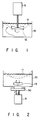
- An example of a conventional stirring method is a method of stirring a reaction solution by using a motor. Fig. 1 shows an example of this method. A solution in a
vessel 10 is stirred by animpeller 12 attached to an end portion of a rotating shaft of a small-sized motor 9. - Fig. 2 shows another example. A freely
movable magnet 13 is placed within thevessel 10. A piece of a magnetic metal 9a below thevessel 10 is rotated by themotor 9. By utilizing an attraction force of themagnet 13, themagnet 13 within thevessel 10 is rotated in accordance with the rotation of the piece of a magnetic metal 9a, thereby stirring the solution. - In these methods, stirring is effected in a two-dimensional manner at the bottom part of the
vessel 10, and the stirring effect does not act at the upper part of the vessel. Thus, an efficiency of the stirring is low and a long time is required for stirring the entire solution. For example, four seconds or more were required for homogenizing a reaction solution of 400 to 600 µℓ. A stirring performance CV (
- Since the stirring incurs rotation of solution, the solution within the
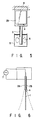
vessel 10 is rotated in a laminar flow, as shown by a broken line in Figs. 1 and 2, resulting in a longer time for stirring. If the rotation speed of themotor 9 is increased to shorten the stirring time, bubbling occurs, or air (air bubbles) is taken in. Depending on the shape or size of the vessel, solution is spilt out of thevessel 10 or splashed. - An example of a conventional stirring device of the above-identified type in which no motor is used is disclosed in U.S. Patent No. 4,612,291. As shown in Fig. 3 (front view) and Fig. 4 (side view),
piezoelectric elements 18a and 18b are attached to both surfaces of a metalthin plate 15, thus constituting a bimorphtype piezoelectric vibrator. A distal end portion of the metalthin plate 15 of the piezoelectric vibrator is connected to a stirringrod 14 of a solid structure made of, e.g., stainless steel. Aproximal end portion 17 of themetal plate 15 is fixed to a support (not shown). As is shown in Fig. 4, anAC voltage 16 is applied to thepiezoelectric elements 18a and 18b, and thepiezoelectric elements 18a and 18b are alternately vibrated and thestirring rod 14 is vibrated as shown by broken lines in Fig. 4. By vibration of thestirring rod 14, the solution within thevessel 10 can be stirred. Since thestirring rod 14 is a solid body, therod 14 as a whole vibrates in a primary mode. - According to this device , since the amplitude of vibration of the stirring
member 14 is proportional to the applied voltage, the stirring time can be decreased by increasing the voltage. However, if the amplitude is greatly increased, the stress of theproximal end portion 17 of the piezoelectric vibrator increases, with the result that the piezoelectric vibrator may be damaged or the connecting portion between themetal plate 15 and thestirring rod 14 may be mechanically broken. Since thestirring rod 14 is placed in the vessel with a fixed width, the vessel may be broken by the vibration of the stirring rod if the amplitude of the vibration greatly increases. Thus, the effect of the stirring is limited. In addition, since the vibration mode is the primary mode, the entire reaction solution is not stirred. Thus, the stirring efficiency is low in this method, as with the case of using the motor. - FR-A-2 305 226 discloses a stirring device having a flexible plate united with an anchor which is suspended in two parallel flat springs. The anchor is coupled with a core of an electromagnet, the coil of which being supplied with an alternating current. Between said two flat springs there is provided a weight attached to the flexible plate. In this prior art stirring device vibration is obtained by moving the anchor by means of supplying an alternating current into said coil of the electromagnet. However, vibration cannot be stopped immediately due to the inertia of said flat springs. Therefore, it is difficult to precisely control the stirring time.
- The present invention has been made in consideration of the above circumstances, and its object is to provide a stirring device capable of homogenizing a reaction solution in a short time.
- The stirring device according to the present invention comprises the features defined in
claim 1. - According to the present invention, a portion of the flexible plate forming a piezoelectric vibrator with the piezoelectric element is used as a stirring member. Thereby, the vibrator can be vibrated in a higher-order mode, the entire solution can be stirred simultaneously, vertical motion of the solution is caused, and the stirring efficiency can be enhanced.
- Additional objects and advantages of the present invention will be set forth in the description which follows, and in part will be obvious from the description, or may be learned by practice of the present invention. The objects and advantages of the present invention may be realized and obtained by means of the instrumentalities and combinations particularly pointed out in the appended claims.
- The accompanying drawings, which are incorporated in and constitute a part of the specification, illustrate presently preferred embodiments of the present invention and, together with the general description given above and the detailed description of the preferred embodiments given below, serve to explain the principles of the present invention in which:
- Fig. 1 shows a conventional stirring device using a motor;
- Fig. 2 shows another conventional stirring device using a motor;
- Fig. 3 is a front view showing a conventional stirring device using a piezoelectric element;
- Fig. 4 is a side view of the conventional stirring device shown in Fig. 3;
- Fig. 5 is a front view of an embodiment of a stirring device according to the present invention;
- Fig. 6 is a side view of the embodiment shown in Fig. 5;
- Fig. 7 shows a model of a vibration system of the embodiment of the stirring device according to the present invention;
- Fig. 8 shows characteristics of the model shown in Fig. 7, wherein a weight is attached on the surface of a metal thin plate;
- Fig. 9 shows characteristics of the model shown in Fig. 7, wherein the weight is not attached;
- Fig. 10 shows characteristics of a stirring time in relation to the weight;
- Figs. 11A and 11B show measurement results of the oscillation mode of the embodiment at a given frequency in the air;
- Figs. 12A and 12B show measurement results of the oscillation mode of the embodiment at another frequency in the air;
- Figs. 13A and 13B show measurement results of the oscillation mode of the embodiment at the given frequency in the water;
- Figs. 14A and 14B show measurement results of the oscillation mode of the embodiment at the other frequency in the water;
- Fig. 15 is a schematic view of an apparatus for examining frequency characteristics of current in the embodiment;
- Fig. 16 is a schematic view of an apparatus for examining frequency characteristics of impedance in the embodiment;
- Fig. 17 shows frequency characteristics examined by the apparatuses shown in Figs. 15 and 16;
- Fig. 18 shows the influence of the vibration frequency on the stirring performance;
- Fig. 19 shows the influence of the load voltage on the stirring performance;
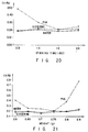
- Fig. 20 shows the influence of the stirring time on the stirring performance; and
- Fig. 21 shows the influence of the weight attached to the piezoelectric vibrator on the stirring performance.
- A preferred embodiment of a stirring device according to the present invention will now be described with reference to the accompanying drawings. Fig. 5 is a front view of the stirring device of a first embodiment, and Fig. 6 is a side view thereof.
-
Piezoelectric elements 2a and 2b formed of ceramics or the like are attached to both sides of a flexible metalthin plate 1 having a soft structure, thus constituting a bimorph-type piezoelectric vibrator. The piezoelectric element may be attached to only one side of the metalthin plate 1, thus constituting a unimorphtype piezoelectric vibrator. - When an AC voltage is applied from a
power supply 7 to the piezoelectric vibrator (piezoelectric elements 2a and 2b), as shown in Fig. 6, the respectivepiezoelectric elements 2a and 2b extend and contract alternately, and the metalthin plate 1 vibrates in a direction perpendicular to the surface of the plate. A proximal end portion of theplate 1 is fixed to asupport 8. In a case of the biochemical analyzer, thesupport 8 is a stirring device supporting arm attached to a housing of the analyzer. - The distal end portion of the
plate 1 extends with the same material having a narrow portion, thus forming astirring blade 3. Theblade 3 is situated within a vessel 5 of a solution as a stirring member. Theblade 3 vibrates in accordance with vibration of the piezoelectric vibrator, and the solution within the vessel 5 is stirred by vibration of theblade 3. - A weight 4 capable of adjusting the ratio in mass of the
blade portion 3 to thepiezoelectric element portion 2a and 2b of the vibrator is attached to the metalthin plate 1 of the piezoelectric vibrator. The weight 4 can be attached to any portion of theplate 1. In this embodiment, for example, as shown in Fig. 5, the weight 4 is attached to a portion adjacent to the proximal end of theblade 3. - Regarding this stirring device, if the amplitude of vibration of the
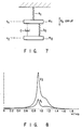
blade 3 is increased, a large bending stress is caused in thepiezoelectric elements 2a and 2b. Thus, it is necessary to reduce the stress, while keeping a large amplitude of vibration. - The means for solving this problem will now be explained by using a model. When the model of a stirring device to which the piezoelectric vibrator is applied is converted to a vibration system, this vibration system can be regarded as a forced-vibration system incurring an attenuation of two degrees of freedom, in the case where the equivalent mass and the spring constant of the main portion (piezoelectric elements) of the piezoelectric vibrator are m1 and k1, the equivalent mass and the spring constant of the stirring portion (blade) of the piezoelectric vibrator are m2 and k2, and the solution resistance is c. Fig. 7 shows the model.
- When displacements of the vibrator (m1) and blade (m2) from the respective equilibrium states are x1 and x2, and an external force P0cosωt is applied from the
piezoelectric elements 2a and 2b to the vibrator part (m1), the following motion equations (simultaneous equations) are obtained.
- To solve the simultaneous equations, P0cosωt of the right hand term is changed to the real number part of P0exp(jωt), i.e., Re[P0exp(jωt)]. Under the condition that


- Substituting these, the above simultaneous equations are expressed as follows:

- From these simultaneous equations, x1 and x2 will be obtained as follows:

- To obtain the real number part of this solution, the phase difference δ1 is defined as follows:

- Using the phase difference δ1, x1 is expressed as follows:

- The forced displacement x1 of the vibrator (m1) in relation to the displacement xst at the static time is given as follows.

- The following constants are determined. Here, y1 is the maximum amplitude of vibration in one direction of the vibrator.
-

-

-

-

-

-

-

-


- If the x1/xst is rewritten, the maximum value y1 is found as follows:

- Similarly, the maximum amplitude y2 of vibration in one direction of the blade is given as follows.

- If δ2 is omitted, the maximum value y2 is as follows:

- Figs. 8 and 9 show the results of simulation of the maximum values y1 and y2 in relation to an actual angular vibration frequency


- As is understood from Figs. 8 and 9, large vibration occurred in the vicinity of the ratio (ω/ω0) of the actual angular vibration frequency ω to the inherent angular vibration frequency ω0 is 0.9. Although the amplitude of the entire stirring device can be controlled by varying the frequency, it is generally desirable that the voltage is low. It is thus desirable that the driving frequency is made to coincide with the inherent frequency ω0 of the vibration system having two degrees of freedom, and the stirring device is used in the resonance state. It is therefore preferable that the amplitude takes a maximum value when the vibration frequency ratio ω/ω0 is about 0.9.
- Fig. 9 shows the state wherein the weight was not used (i.e.,

blade 3 indicated by broken lines in Fig. 6 corresponds to the case of Fig. 8. - In this manner, the ratio R in mass of the blade portion to the piezoelectric element portion of the vibrator is varied (specifically, R < 1) and the mass m1 of the piezoelectric vibrator or the main vibrating system is made greater than the mass m2 of the blade. Thereby, the amplitude y2 of the blade or the to-be-vibrated system can be made greater than the amplitude y1 of the piezoelectric vibrator or the main vibrating system. The reason for this is that the energy of the main vibrating system can be absorbed by the blade portion (vibration is increased by a vibration-absorbing device) on the basis of the same principle as that of a vibration-absorbing device.
- As a result, the amplitude y1 of the piezoelectric vibrator can be made less than the amplitude y2 of the blade, the stirring time (

- In the present invention, the piezoelectric vibrator is given a weight, and m1 is made greater than m2, i.e., R < 1. Thereby, stirring can be effectively performed, and the amplitude of the piezoelectric vibrator is reduced, thus preventing damage of the piezoelectric element and damage of the metal thin plate of the boundary portion between the piezoelectric vibrator and the blade.
- Fig. 10 shows experimental results of the stirring time t (second) in relation to the mass ratio R. As is understood from Fig. 10, more than four seconds were required in the conventional motor system whereas in the present system the stirring time can be reduced to 1.0 to 1.3 seconds by properly setting the mass ratio R. The reason for this is that since the
blade 3 is flexible, vibration is performed in the higher-order mode, with the result that disturbance of solution, as indicated byarrows 6 in Fig. 5, occurs in the vessel 5 and the solution within the vessel is totally stirred. Thus, unlike the prior art, air bubbles are not taken in solution, or solution is not spilt over the vessel. Thus, the solution can be homogenized in a short period of time. - Figs. 11A to 14B show measurement results of the oscillation mode of the stirring device. These show output waveforms (amplitudes) of the piezoelectric vibrator driven by AC 20 V, under the conditions that 600 µℓ of water was used and a weight of 0.5 g was attached to the bimorph-type piezoelectric vibrator having thickness of 0.2 mm (i.e., R = 0.04 to 0.06). The length of the blade was 50 mm.
- Figs. 11A, 12A, 13A, and 14A show the characteristic of an output waveform at the position of the weight, and Figs. 11B, 12B, 13B, and 14B show the characteristic of an output waveform at the distal end of the blade. Figs. 11A and 11B show the case where measurement was performed in the air with the driving frequency of 48 Hz, Figs. 12A and 12B the case where measurement was performed in the air with the driving frequency of 101 Hz, Figs. 13A and 13B the case where measurement was performed in the water with the frequency of 41 Hz, and Figs. 14A and 14B the case where measurement was performed in the water with the frequency of 115 Hz. In each state, the amplitude was observed by the naked eyes.
- In the case of Figs. 11A and 11B, the amplitude was 3 mm at the position of the weight and 42 mm at the distal end. In the case of Figs. 12A and 12B, it was 5 mm at the position of the weight and 11 mm at the distal end. In the case of Figs. 13A and 13B, it was 0 mm at the position of the weight and 2 mm at the distal end. In the case of Figs. 14A and 14B, it was 2.5 mm at the position of the weight and 2.5 mm at the distal end. Figs. 14A and 14B show the case of actual stirring. As is understood from Figs. 14A and 14B, the period of the vibration at the weight position and that at the distal end position differed from each other so that it can be regarded that the stirring device of the present invention vibrates in the second-order mode.
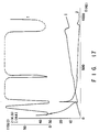
- Next, the frequency characteristics will now be explained. Current was measured by the system shown in Fig. 15, and impedance was measured by the system shown in Fig. 16. In Fig. 15, a
vessel 20 contains a solution (600 µℓ) of 1.5 % of PVA (polyvinyl alcohol). A stirringdevice 22 put in thevessel 20 is connected to apower supply 24. A current value I (mA) at the time the frequency is variable is measured by an oscilloscope 28 via aresistor 26 of 1KΩ. In Fig. 16, similarly, anLCR meter 30 is connected to the stirringdevice 22, and the impedance Z (KΩ) at the time the frequency is variable is measured. - The measurement results, as well as stirring time t (second), are shown in Fig. 17. As is understood from Fig. 17, the stirring device of the present system vibrated in the higher-order mode, and stirring can be efficiently performed by using the second-order resonance in the vicinity of frequency 159 Hz. Thus, the driving frequency of the piezoelectric vibrator according to the present invention is set to 159 Hz. Large bubbles were generated and the surface of water was undulated by the third-order resonance in the vicinity of frequency 415 Hz. Small bubbles were generated and bubbling was spread over the surface of water by the fourth-order resonance in the vicinity of frequency 900 Hz.
- Lastly, the influence of various parameters on the stirring performance CV (

- Fig. 18 shows the influence of the vibration frequency on the stirring performance. A load voltage was 20.04 V, and a stirring time was 1.9 seconds. As is understood from Fig. 18, when the vibration frequency was 120 Hz, the CV was low, in particular, in the PVA solution. In the PVA solution, the CV was bad when the vibration frequency was higher or lower than 120 Hz. In water and the glycerine solution, a large variation did not appear in all measurement ranges, and the CV was kept at about 0.20 %. That is, the CV was bad when the vibration frequency was low since the effect of stirring was insufficient due to the viscosity of reagent. On the other hand, the CV was lowered when the vibration frequency was high since the reagent was bubbled.
- Fig. 19 shows the influence of the load voltage on the stirring performance. The load vibration frequency was 120 Hz, and the stirring time was 1.9 seconds. As is understood from Fig. 19, up to 30 V, as the load voltage increased, the CV substantially decreased in all samples. The CV slightly increased when the load voltage increased to 35 V. If the load voltage is high, the variation of the CV between samples is small.
- Fig. 20 shows the influence of the stirring time on the stirring performance. The load frequency was 120 Hz and the load voltage was 20 V. The target value of CV (< 0.3 %) was attained in any samples by the stirring time of 1.9 seconds. The stirring performance for the PVA solution only increased by increasing the stirring time.
- Fig. 21 shows the influence of the weight of the blade on the stirring performance. The load vibration frequency was 120 Hz, the load voltage was 20 V, and the stirring time was 1.9 seconds. A preferable result was obtained at the time of the weight of 0.75 g. The stirring performance for the PVA solution only changed by changing the weight.
- Although characteristics are not shown, it is confirmed that since the
metal plate 1 was very thin and coated with FEP, the amount of washing water which stirring device brings from the washing bath into the reaction vessel and the amount of water which stirring device brings out of the reaction vessel, i.e., the amount of carried over were negligible. It is also confirmed that a variation of the CV between individual stirring devices was small. - As has been described above, according to the stirring device of the present embodiment, the piezoelectric vibrator formed of piezoelectric elements attached to the metal thin plate is used, the distal end of the vibrator (metal thin plate) is extended to form the stirring blade, and the weight is attached between the piezoelectric elements and the stirring blade, thereby adjusting the amplitude of vibration of the distal end portion of the stirring blade such that the amplitude of vibration of the distal end portion of the stirring blade is made larger than that of the piezoelectric element. The voltage applied to the piezoelectric element and the frequency of the vibration are adjusted so that the stirring device is vibrated in the higher-order mode. Thereby, at the time of stirring, the entire reaction solution is moved simultaneously, and vertical motion is caused. The entire reaction solution is homogenized in a short time, and precision in analysis is enhanced. Further, since the metal thin plate forms the main portion of the vibrator and the blade portion, the number of connection portions is reduced, and factors of faults are reduced. Therefore, the reliability of the apparatus is increased, and the operator's work load is reduced. The reduction in the number of mechanical parts simplifies the structure of the unit and lowers the cost.
- The vibration-generating means is not limited to the piezoelectric element. A voice coil motor or a magnetostrictive element may be used.
- The number of the vibration-generating elements attached to each surface of the metal plate is not limited to one. More than two piezoelectric elements, voice coil motors, or magnetostrictive elements may be attached to each surface of the metal plate.
- The piezoelectric element can be applicable to both an actuator and a sensor, because of its operational principle. Thus, if a part of the piezoelectric element is used as an actuator and another part is used as a sensor, the driving of piezoelectric element can be controlled in a feedback manner in accordance with the vibration state detected by the sensor. Thereby, stirring can always be performed under optimal conditions in accordance with the quantity of the solution and the variation in viscosity.
- In the embodiment, the vibrator is vibrated in the lateral direction; however, it may be vibrated in the vertical direction. In this case, the blade may be replaced by a stirring rod having a horizontal plate at its distal end or the impeller as shown in Fig. 1. The degrees of freedom are increased with respect to the position of attachment of the stirring device, without the need to consider the deviation angle of the blade.
- In the embodiment, a portion of the metal plate of the vibrator is extended to form the blade; however, the stirring portion may also be formed as part of the piezoelectric vibrator. That is, it is possible to use the piezoelectric vibrator of the unimorph-type or bimorophtype itself as the stirring device.
- As has been described above, the present invention can provide a stirring device wherein, since a thin, flexible metal plate is used as material of the stirring member, vibration can be performed in the higher-order mode, the entire reaction solution can be moved simultaneously, and the reaction solution can be moved vertically. Consequently, the reaction solution can be homogenized in a short stirring time, and the treatment of specimen can be performed quickly.
Claims (5)
- A stirring device comprising a flexible plate (1) which includes a narrow stirring portion (3) to be positioned in a vessel and a wide main portion fixed at one end thereof, a vibration means (2a, 2b) which is attached to a surface of the wide main portions of said flexible plate (1) for vibrating the flexible plate (1), and a weight (4) which is attached to said flexible plate (1), said weight acting as a vibration-absorbing device making the amplitude of vibration of the stirring portion larger than an amplitude of the main portion, and said weight having a mass value for setting the mass ratio (R) of the mass m2 of the narrow stirring portion (3) to the mass m1 of the wide main portion having attached thereto the vibration means (2a, 2b), in the range 0.04 to 0.06.
- A stirring device according to claim 1, characterized in that the weight (4) is attached to a portion of the flexible plate (1) between the vibration means (2a, 2b) and the stirring portion (3).
- A stirring device according to claim 1 or 2, characterized in that said vibration means comprises a piezoelectric element (2a, 2b), which is attached to one surface of the main portion, the piezoelectric element forming a unimorph-type piezoelectric vibrator.
- A stirring device according to claim 1 or 2, characterized in that said vibration means comprises two piezoelectric elements (2a, 2b), which are attached to both surfaces of the main portion, the two piezoelectric elements forming a bimorph-type piezoelectric vibrator.
- A stirring device according to claim 3 or 4, characterized in that said piezoelectric element(s) is/are attached to an entire surface of said main portion (1).
Applications Claiming Priority (2)
| Application Number | Priority Date | Filing Date | Title |
|---|---|---|---|
| JP03137994A JP3135605B2 (en) | 1991-06-10 | 1991-06-10 | Stir bar |
| JP137994/91 | 1991-06-10 |
Publications (2)
| Publication Number | Publication Date |
|---|---|
| EP0518281A1 EP0518281A1 (en) | 1992-12-16 |
| EP0518281B1 true EP0518281B1 (en) | 1997-09-24 |
Family
ID=15211584
Family Applications (1)
| Application Number | Title | Priority Date | Filing Date |
|---|---|---|---|
| EP92109730A Expired - Lifetime EP0518281B1 (en) | 1991-06-10 | 1992-06-10 | Stirring device |
Country Status (4)
| Country | Link |
|---|---|
| US (1) | US5449493A (en) |
| EP (1) | EP0518281B1 (en) |
| JP (1) | JP3135605B2 (en) |
| DE (1) | DE69222360T2 (en) |
Families Citing this family (27)
| Publication number | Priority date | Publication date | Assignee | Title |
|---|---|---|---|---|
| JP3756296B2 (en) | 1997-08-20 | 2006-03-15 | 株式会社東芝 | Stirrer |
| DE19832697C2 (en) * | 1998-07-21 | 2000-11-16 | Eurocopter Deutschland | Device and method for reducing vibrations along a vibration propagation, in particular in a helicopter |
| GB9924780D0 (en) | 1999-10-21 | 1999-12-22 | Glaxo Group Ltd | Medicament dispenser |
| GB9924808D0 (en) | 1999-10-21 | 1999-12-22 | Glaxo Group Ltd | Medicament dispenser |
| DE10024353A1 (en) * | 2000-05-17 | 2001-12-13 | Endress Hauser Gmbh Co | Method and device for determining the fill level of a medium in a container |
| JP2001327846A (en) * | 2000-05-24 | 2001-11-27 | Naoyuki Aoyama | Method for agitating fine liquid droplet and device used in the method |
| US20040136873A1 (en) * | 2003-01-09 | 2004-07-15 | Argonaut Technologies, Inc. | Modular reactor system |
| CA2532878A1 (en) * | 2003-07-28 | 2005-02-10 | Bryan James Larkin | A spray applicator |
| CN100594382C (en) | 2004-03-23 | 2010-03-17 | 松下电器产业株式会社 | Stirring method, reaction vessel, measuring apparatus using the reaction vessel, and measuring method |
| JP4615342B2 (en) * | 2004-03-23 | 2011-01-19 | パナソニック株式会社 | Stirring method, cell, measuring device using the same, and measuring method |
| DE102006005242A1 (en) * | 2006-02-03 | 2007-08-16 | Wilhelm Dr. Irvine Degen | Jogger arrangement and method for producing material columns in the ground |
| US8159107B2 (en) * | 2006-06-02 | 2012-04-17 | Microzeus Llc | Micro rotary machine and methods for using same |
| US9156674B2 (en) * | 2006-06-02 | 2015-10-13 | MicroZeus, LLC | Micro transport machine and methods for using same |
| US8915158B2 (en) * | 2006-06-02 | 2014-12-23 | MicroZeus, LLC | Methods and systems for micro transmissions |
| US8282284B2 (en) * | 2006-06-02 | 2012-10-09 | MicroZeus, LLC | Methods and systems for micro bearings |
| WO2007143623A2 (en) | 2006-06-02 | 2007-12-13 | Stalford Harold L | Methods and systems for micro machines |
| US8134276B2 (en) * | 2006-06-02 | 2012-03-13 | MicroZeus, LLC | Methods and systems for positioning micro elements |
| US8884474B2 (en) * | 2006-06-02 | 2014-11-11 | MicroZeus, LLC | Method of fabricating a micro machine |
| US8122973B2 (en) | 2008-05-21 | 2012-02-28 | Stalford Harold L | Three dimensional (3D) robotic micro electro mechanical systems (MEMS) arm and system |
| JP5216562B2 (en) * | 2008-12-15 | 2013-06-19 | 株式会社東芝 | Automatic analyzer and stirrer |
| CN103223313A (en) * | 2012-01-30 | 2013-07-31 | 株式会社东芝 | Stirrer and sample analytical equipment |
| JP6318177B2 (en) * | 2013-02-11 | 2018-04-25 | アンドリュー イー. ブロック | Device for producing asymmetric vibrations |
| JP6176842B2 (en) * | 2013-07-23 | 2017-08-09 | 東芝メディカルシステムズ株式会社 | Automatic analyzer |
| JP2015199037A (en) * | 2014-04-08 | 2015-11-12 | 株式会社東芝 | Agitation device and automatic analyzer |
| JP6575984B2 (en) * | 2015-12-28 | 2019-09-18 | D−テック合同会社 | Solution stirring device |
| JP2018091743A (en) * | 2016-12-05 | 2018-06-14 | キヤノンメディカルシステムズ株式会社 | Clinical examination device |
| TWI667871B (en) * | 2018-08-07 | 2019-08-01 | 國立交通大學 | Fan device |
Family Cites Families (14)
| Publication number | Priority date | Publication date | Assignee | Title |
|---|---|---|---|---|
| US4026572A (en) * | 1970-02-17 | 1977-05-31 | Koji Yoshioka | Means for isolating a vibration or shock |
| GB1414880A (en) * | 1973-08-06 | 1975-11-19 | Bruyne N A De | Oscillatory stirrers |
| SE389972B (en) * | 1975-03-27 | 1976-11-29 | Autochem Instrument Ab | DEVICE FOR DOSING A LIQUID INTO A PROVER AND FOR AGITATING THE CONTENTS OF THE PROVER |
| US4211121A (en) * | 1976-09-01 | 1980-07-08 | Fmc Corporation | Vibrator with eccentric weights |
| US4550812A (en) * | 1978-08-04 | 1985-11-05 | United Technologies Corporation | Fixed position, fixed frequency pendular-type vibration absorber with frequency linearization |
| SU871847A2 (en) * | 1979-01-08 | 1981-10-15 | Государственный Институт По Проектированию Метизных Заводов | Unbalance vibration exciter |
| JPS5667731A (en) * | 1979-11-06 | 1981-06-08 | Nissan Motor Co Ltd | Knocking sensor |
| DE3027533C2 (en) * | 1980-07-21 | 1986-05-15 | Telsonic Aktiengesellschaft für elektronische Entwicklung und Fabrikation, Bronschhofen | Process for generating and emitting ultrasonic energy in liquids and an ultrasonic resonator for carrying out the process |
| US4612291A (en) * | 1984-09-04 | 1986-09-16 | American Monitor Corporation | Method and apparatus for mixing serum and reagents for chemical analysis |
| US4602184A (en) * | 1984-10-29 | 1986-07-22 | Ford Motor Company | Apparatus for applying high frequency ultrasonic energy to cleaning and etching solutions |
| US4780062A (en) * | 1985-10-09 | 1988-10-25 | Murata Manufacturing Co., Ltd. | Piezoelectric fan |
| US4778279A (en) * | 1987-08-20 | 1988-10-18 | Bodine Albert G | Sonic agitator with multi phased vibration bars |
| JP2690907B2 (en) * | 1987-09-25 | 1997-12-17 | 株式会社日立製作所 | Composite piezoelectric motor |
| JPS63232829A (en) * | 1987-11-06 | 1988-09-28 | Reika Kogyo Kk | Static mixer |
-
1991
- 1991-06-10 JP JP03137994A patent/JP3135605B2/en not_active Expired - Lifetime
-
1992
- 1992-06-10 DE DE69222360T patent/DE69222360T2/en not_active Expired - Fee Related
- 1992-06-10 EP EP92109730A patent/EP0518281B1/en not_active Expired - Lifetime
-
1993
- 1993-12-28 US US08/173,934 patent/US5449493A/en not_active Expired - Lifetime
Also Published As
| Publication number | Publication date |
|---|---|
| DE69222360D1 (en) | 1997-10-30 |
| JP3135605B2 (en) | 2001-02-19 |
| US5449493A (en) | 1995-09-12 |
| EP0518281A1 (en) | 1992-12-16 |
| JPH04363665A (en) | 1992-12-16 |
| DE69222360T2 (en) | 1998-04-30 |
Similar Documents
| Publication | Publication Date | Title |
|---|---|---|
| EP0518281B1 (en) | Stirring device | |
| KR920003532B1 (en) | Vibration type rheometer apparatus | |
| JP2730673B2 (en) | Method and apparatus for measuring physical properties using cantilever for introducing ultrasonic waves | |
| EP0187324A1 (en) | Apparatus for self-resonant vibrational mixing | |
| WO2009131185A1 (en) | Device for measuring viscosity/elasticity and method for measuring viscosity/elasticity | |
| JP2015155906A (en) | Method and rheometer for determining measurement data of sample | |
| JP2004510131A (en) | Dynamic tensile tester | |
| EP2895854B1 (en) | Blood coagulometer and method | |
| KR20150060908A (en) | Method and device for measuring fluid body physical properties | |
| EP0501976B1 (en) | Rheometer | |
| US5571952A (en) | Electronic viscometer | |
| EP3770902A1 (en) | Acoustic micro imaging device having at least one balanced linear motor assembly | |
| JP4964229B2 (en) | Apparatus and method for moving a liquid container | |
| WO2019113159A1 (en) | Intertial torque device for viscometer calibration and rheology measurements | |
| EP1381842B1 (en) | Fluid properties evaluation | |
| US4612291A (en) | Method and apparatus for mixing serum and reagents for chemical analysis | |
| EP3382370A1 (en) | Probe arrangement and method for rheometric measurements with a disposable probe and remote readability | |
| JP3756296B2 (en) | Stirrer | |
| US5509298A (en) | Apparatus and method for measuring visco-elastic characteristics of a sample | |
| US6622114B1 (en) | Method for determining the weight of a probe of a coordinate measuring machine | |
| JP7049465B2 (en) | Two-dimensional nanoindentation device and method | |
| JP3738593B2 (en) | Method for measuring excitation force of vibration generator | |
| JPH0886728A (en) | Tester for evaluating strength reliability | |
| US20170328883A1 (en) | Blood coagulometer and method | |
| RU2193769C2 (en) | Method measuring characteristics of surface magnetic field with use of scanning sounding microscope |
Legal Events
| Date | Code | Title | Description |
|---|---|---|---|
| PUAI | Public reference made under article 153(3) epc to a published international application that has entered the european phase |
Free format text: ORIGINAL CODE: 0009012 |
|
| 17P | Request for examination filed |
Effective date: 19920610 |
|
| AK | Designated contracting states |
Kind code of ref document: A1 Designated state(s): DE FR |
|
| 17Q | First examination report despatched |
Effective date: 19940802 |
|
| GRAG | Despatch of communication of intention to grant |
Free format text: ORIGINAL CODE: EPIDOS AGRA |
|
| GRAH | Despatch of communication of intention to grant a patent |
Free format text: ORIGINAL CODE: EPIDOS IGRA |
|
| GRAH | Despatch of communication of intention to grant a patent |
Free format text: ORIGINAL CODE: EPIDOS IGRA |
|
| GRAA | (expected) grant |
Free format text: ORIGINAL CODE: 0009210 |
|
| AK | Designated contracting states |
Kind code of ref document: B1 Designated state(s): DE FR |
|
| REF | Corresponds to: |
Ref document number: 69222360 Country of ref document: DE Date of ref document: 19971030 |
|
| ET | Fr: translation filed | ||
| PLBE | No opposition filed within time limit |
Free format text: ORIGINAL CODE: 0009261 |
|
| STAA | Information on the status of an ep patent application or granted ep patent |
Free format text: STATUS: NO OPPOSITION FILED WITHIN TIME LIMIT |
|
| 26N | No opposition filed | ||
| PGFP | Annual fee paid to national office [announced via postgrant information from national office to epo] |
Ref country code: FR Payment date: 20010511 Year of fee payment: 10 |
|
| PGFP | Annual fee paid to national office [announced via postgrant information from national office to epo] |
Ref country code: DE Payment date: 20020701 Year of fee payment: 11 |
|
| PG25 | Lapsed in a contracting state [announced via postgrant information from national office to epo] |
Ref country code: FR Free format text: LAPSE BECAUSE OF NON-PAYMENT OF DUE FEES Effective date: 20030228 |
|
| REG | Reference to a national code |
Ref country code: FR Ref legal event code: ST |
|
| PG25 | Lapsed in a contracting state [announced via postgrant information from national office to epo] |
Ref country code: DE Free format text: LAPSE BECAUSE OF NON-PAYMENT OF DUE FEES Effective date: 20040101 |