KR920003532B1 - Vibration type rheometer apparatus - Google Patents
Vibration type rheometer apparatus Download PDFInfo
- Publication number
- KR920003532B1 KR920003532B1 KR1019880015197A KR880015197A KR920003532B1 KR 920003532 B1 KR920003532 B1 KR 920003532B1 KR 1019880015197 A KR1019880015197 A KR 1019880015197A KR 880015197 A KR880015197 A KR 880015197A KR 920003532 B1 KR920003532 B1 KR 920003532B1
- Authority
- KR
- South Korea
- Prior art keywords
- continuously
- magnitude
- drive current
- control means
- vibrator
- Prior art date
Links
Images


Classifications
-
- G—PHYSICS
- G01—MEASURING; TESTING
- G01H—MEASUREMENT OF MECHANICAL VIBRATIONS OR ULTRASONIC, SONIC OR INFRASONIC WAVES
- G01H11/00—Measuring mechanical vibrations or ultrasonic, sonic or infrasonic waves by detecting changes in electric or magnetic properties
- G01H11/06—Measuring mechanical vibrations or ultrasonic, sonic or infrasonic waves by detecting changes in electric or magnetic properties by electric means
-
- G—PHYSICS
- G01—MEASURING; TESTING
- G01N—INVESTIGATING OR ANALYSING MATERIALS BY DETERMINING THEIR CHEMICAL OR PHYSICAL PROPERTIES
- G01N11/00—Investigating flow properties of materials, e.g. viscosity, plasticity; Analysing materials by determining flow properties
- G01N11/10—Investigating flow properties of materials, e.g. viscosity, plasticity; Analysing materials by determining flow properties by moving a body within the material
- G01N11/16—Investigating flow properties of materials, e.g. viscosity, plasticity; Analysing materials by determining flow properties by moving a body within the material by measuring damping effect upon oscillatory body
Abstract
내용 없음.No content.
Description
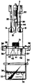
제1도는 본 발명에 사용되는 진동 점도계의 일부를 절제한 단면도로 표시하는 측면도.1 is a side view showing a cross-sectional view of a part of a vibratory viscometer used in the present invention.
제2도는 제1도에 도시한 요부를 분해하여 도시하는 측면도.2 is an exploded side view showing the main portion shown in FIG.
제3도는 본 발명의 진폭 레오미터장치를 설명하는 블록도.3 is a block diagram illustrating an amplitude rheometer device of the present invention.
제4도, 제5도 및 제6도는 본 발명에 의한 진동 레오미터장치에 의하여 측정된 샘플의 유동특성을 도시하는 설명도로서, 제4도는 샘플이 마요네즈인 경우 그래프. 제5도는 코울드크리임인 경우 그래프, 제6도는 유액의 경우의 그래프.4, 5 and 6 are explanatory views showing the flow characteristics of the sample measured by the vibration rheometer device according to the present invention, Figure 4 is a graph when the sample is mayonnaise. 5 is a graph in the case of cold cream, and FIG. 6 is a graph in the case of latex.
제7도는 여러가지의 측정 패턴을 표시하는 설명도.7 is an explanatory diagram showing various measurement patterns.
* 도면의 주요부분에 대한 부호의 설명* Explanation of symbols for main parts of the drawings
1 : 프레임측 2 : 지지블록1: frame side 2: support block
3 : 지지캠 4 : 바이브레이터 서브샘플리3: support cam 4: vibrator subsample
5 : 리프스프링 6 : 나사5: leaf spring 6: screw
7 : 고정쇠 8 : 중간플레이트7: clamp 8: intermediate plate
9 : 센서플레이트 12 : 전자코일9: Sensor plate 12: Electronic coil
14 : 검출기 21 : 프로브14 detector 21 probe
51 : 구동유닛 53 : 서모미터51: drive unit 53: thermometer
54 : 발진기 55 : 증폭기54: oscillator 55: amplifier
56 : 제어유닛 57 : 전류계56
62 : 기록유닛62: recording unit
본 발명은 유체의 변형과 유동의 현상을 측정하는 레오미터(rheometer)에 관한 것으로, 다시 상세히 말하면 샘플내에서 진동하는 1쌍의 음차상 멤버를 가지는 점도계를 포함하는 레오미터장치에 관한다.FIELD OF THE INVENTION The present invention relates to rheometers for measuring deformation of fluids and phenomena of flow, and more particularly to rheometer devices comprising a viscometer having a pair of tuning fork members that vibrate in a sample.
단순한 액체, 예를들면 물, 알콜, 글리세린등의 유동성은 점성률에 차이는 있으나, 이들은 뉴톤점성, 즉 유동시에는 응력에 비례한 변형속도를 표시한다. 이것에 대하여 비교적 복잡한 구조를 가지는 걸쭉한 액체, 예를들면 페인트, 치약, 마요네즈, 코울드크리임은 외력이 일정한 치를 초과하지 않으면 유동이 시작되지 않는 비뉴톤 점성을 나타내는 것으로 알려져 있다. 또 한편, 용기내에 넣은 겔상 물질이 휘저었거나 진동을 받으면 졸상으로 변하고 그것을 방치하므로써 재차 겔상으로 되돌아가는 성상은 틱소트로피로 호칭되고 있다.The fluidity of simple liquids, such as water, alcohols, glycerin, etc., differs in viscosity, but they represent Newtonian viscosity, that is, strain rate proportional to stress in flow. On the other hand, thick liquids having a relatively complicated structure, such as paint, toothpaste, mayonnaise and cold cream, are known to exhibit non-Newtonian viscosities in which flow does not start unless the external force exceeds a certain value. On the other hand, when the gelled substance in the container is agitated or vibrated, the gelled substance is converted into a sol form and is returned to the gel form by being left to stand again and is called thixotropy.
뉴톤 점성인지 비뉴통 점성인지의 측정 특히 틱소트로피의 정도는 회전 점도계의 회전수를 연속적으로 증가시킬 때와 연속적으로 감소시킬때에 나타나는 히스테린스폐곡선의 면적을 평가하므로써 알 수가 있다. 회전 점도계에 있어서는 점성 유체중에서 원통체를 회전시켜서 그 원통체에 작용하는 점성에 의한 토오크를 측정하므로써 점도를 구한다. 공축의 이중 원통형에 있어서는 내부통과 외부통과의 사이에 유체를 넣고, 그 외부통을 회전했을때 내부통에 작용하는 토오크를 측정한다. 이측정은 내부통을 토오션와이어로 매달고, 그 토오션와이어의 비틀음각을 구하므로써 실시된다. 회전체의 각 속도를 변경할 수 있도록 하여 그것에 대응하는 스트레인 속도를 변경할 수 있도록하면 비뉴톤 점성 유체의 유동 특성의 측정에 적용할 수 있는 것이다.Determination of Newtonian Viscosity or Non-Newtonian Viscosity The degree of thixotropy, particularly the degree of thixotropy, can be determined by evaluating the area of the hysteresis closed curve that occurs when the rotational viscometer continuously increases and decreases continuously. In a rotational viscometer, a viscosity is calculated | required by rotating the cylinder in a viscous fluid, and measuring the torque by the viscosity acting on the cylinder. In the double cylinder of a coaxial shaft, a fluid is put between an inner cylinder and an outer cylinder, and the torque applied to the inner cylinder when the outer cylinder is rotated is measured. This measurement is carried out by suspending the inner cylinder to the torsion wire and finding the torsional depression of the torsion wire. The ability to change the angular velocity of the rotor and thus the corresponding strain rate can be applied to the measurement of the flow properties of non-Newtonian viscous fluids.
그러나, 측정할 샘플에 따라서 회전체의 형상을 변경하는 것이 필요하고, 또 그 회전체의 사용후의 세정도 복작하므로 취급상 문제가 있다. 이외에 회전체의 관성이나 샘플의 유동에 의한 영향을 받기 때문에 회전체의 제어가능한 각 속도의 범위가 좁고, 여러가지의 측정 패턴을 선택할 수가 없다.However, it is necessary to change the shape of the rotating body in accordance with the sample to be measured, and since the cleaning after use of the rotating body is also duplicated, there is a problem in handling. In addition, since it is influenced by the inertia of the rotating body and the flow of the sample, the range of each controllable speed of the rotating body is narrow and various measurement patterns cannot be selected.
본 발명의 일반적인 목적은 종래의 회전 점도계를 사용하는 레오미터에 있어서의 상기한 바와 같은 결점을 제거할 수 있는 신규의 레오미터 장치를 제공하는 데에 있다.It is a general object of the present invention to provide a novel rheometer device capable of eliminating the above-described drawbacks in rheometers using conventional rotational viscometers.
특히 본 발명의 목적은 여러가지의 측정 패턴을 선택할 수 있도록 하기 위하여 측정할 샘플에 대하여 외력을 가하는 방법이나 또는 스트레인 속도를 광범위하게 변경할 수 있는 레오미터를 제공하는 것이다.In particular, it is an object of the present invention to provide a method for applying an external force to a sample to be measured or a rheometer which can vary widely the strain rate in order to be able to select various measurement patterns.
또한, 본 발명의 목적은 취급이 간단하고, 조작이 용이한 레오미터장치를 제공하는 데에 있다.It is also an object of the present invention to provide a rheometer device with simple handling and easy operation.
본 발명에 의하면 샘플내에서 진동하는 1쌍의 음차상멤버를 가지는 점도계를 포함하는 진동레오미터장치를 제공할 수 있다. 1쌍의 음차상 멤버를 가지는 진동 점도계는 1986년 7월29일에 발생된 본 발명자등에 의한 "점성측정장치"로 명명된 미국 특허번호 제4,602,505호(대응 유럽특허 공개번호 제112,156호)에 의하여 알려져 있다. 또 이 형식의 개량된 진동점도게는 1988년 3월 8일에 발행한 본 발명자등에 의한 "진동형점성측정장치용 조정"로 명명된 미국 특허번호 제4,729,237호(대응 유럽특허 공개번호 제233,408호)에 제안되고 있다. 이들의 진동점도계에 의하면 1쌍의 바이브레이터서브어셈블리를 포함하는 음차의 바이브레이터 수단으로서, 각 바이브레이터서브어셈블리는 그 자유단에 측정할 샘플내에 삽입되는 센서플레이트를 가지고 있는 것과, 상기 1쌍의 바이브레이터서브어셈블리에 진동을 부여하는 구동유닛과, 상기 샘플내에 삽입된 센서플레이트가 받는 점성저항에 의하여 변화하는 상기 1쌍의 바이브레이터서브어셈블리의 진폭을 검출하여 그 진폭을 표시하는 전기신호로 변환하는 검출기를 구비하고 있다.According to the present invention, a vibration rheometer device including a viscometer having a pair of tuning fork phase members vibrating in a sample can be provided. A vibratory viscometer having a pair of tuning fork phase members is described by US Patent No. 4,602,505 (corresponding European Patent Publication No. 112,156), entitled "Viscosity Measurement Device" by the inventors, etc., generated on July 29, 1986. Known. The improved vibration viscosity of this type is also described in US Patent No. 4,729, 237 (corresponding European Patent Publication No. 233,408), entitled "Adjustment for Vibration Viscosity Measurement Devices," published on March 8, 1988. Is proposed. According to these vibration viscometers, a vibrator means of a tuning fork including a pair of vibrator subassemblies, each vibrator subassembly has a sensor plate inserted into a sample to be measured at its free end, and the pair of vibrator subassemblies And a detector for detecting the amplitude of the pair of vibrator subassemblies that vary according to the viscous resistance received by the sensor plate inserted into the sample, and converting the amplitude into an electrical signal indicating the amplitude. have.
구동유닛은 전자코일과 영구자석과의 조합으로 구성되고, 1쌍의 바이브레이터서브어셈블리를 동일주파수하에서 서로 반대위상즉 180도의 위상차를 가지고 진동시킨다. 지금까지 제안된 진동점도계에서는 구동주파수는 30Hz이고, 무부하시의 편진폭은 20미크론으로 일정하게 유지한다.The drive unit is composed of a combination of an electromagnetic coil and a permanent magnet, and vibrates a pair of vibrator subassemblies with a phase difference of 180 degrees out of phase with each other under the same frequency. In the vibration viscometer proposed so far, the driving frequency is 30 Hz and the uneven load amplitude is kept at 20 microns.
본 발명의 특징은 상기의 설명과 같은 공지의 진동점도계의 구성요소 이외에 상기 구동유닛에 대한 구동전류를 두단계로 또한 연속적으로 변화시키는 제어유닛과, 상기 검출기의 출력에 있어서의 상기 구동전류의 변화에 응답하는 상기 1쌍의 바이브레이터서브어셈블리의 진폭치의 변화를 플로트하는 기록수단을 추가로 구비하고 있는 점에 있다. 구동유닛에 대한 구동전류의 크기의 연속적은 변화는 1쌍의 바이브레이터서브어셈블리에 대한 가진력의 연속적인 변화에 나타나므로, 이 가진력의 변화에 응답하는 진폭의 변화를 연속적으로 검출하면 유체의 운동에 있어서의 시간적인 변화를 표현하는 양을 측정할 수가 있다. 이 경우 유체에 동심원상의 유동을 발생시키는 종래의 회전점도계를 사용하는 레오미터에 대하여 본 발명에서는 1쌍의 바이브레이터 서브어셈블리에 의한 미소진동을 발생시키는 것에 불과하기 때문에 그 가진력의 증가법 및 크기의 제어에 의한 측정패턴은 상당한 자유도를 가질 수 있다. 이 측정패턴의 대표적인 예에 있어서는 구동전류의 제어는 다음과 같다.Features of the present invention include a control unit for continuously and continuously changing the drive current for the drive unit in two stages in addition to the components of the known vibration viscometer as described above, and the change of the drive current at the output of the detector. The present invention further comprises recording means for plotting a change in amplitude value of the pair of vibrator subassemblies in response to. Since the continuous change in the magnitude of the drive current for the drive unit appears as a continuous change in the excitation force for a pair of vibrator subassemblies, continuous detection of the change in amplitude in response to the change in the excitation force results in We can measure the amount that represents the temporal change of. In this case, the rheometer using a conventional rotational viscometer which generates a concentric flow in the fluid, in the present invention, because only a small vibration is generated by a pair of vibrator subassembly, the method of increasing the excitation force and control of the magnitude The measurement pattern by can have a considerable degree of freedom. In the representative example of this measurement pattern, the control of the drive current is as follows.
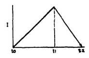
패턴 1 : 시간 t0에서 t1까지의 사이, 무단계로 또한 연속적으로 증대시키고, 이어서 t1에서 t2까지의 사이, 무단계로 또한 연속적으로 감소시킨다.Pattern 1: Increases steplessly and continuously, from time t0 to t1, and then continuously and steplessly, from t1 to t2.
패턴 2 : 상기 패턴 1과 동일하게 시간 t1까지는 연속적으로 증대시키고, 이 시간 t1이상은 일정하게 호올드 한다.Pattern 2: Similarly to
패턴 3 : 상기 패턴 1과 동일하게 시간 t1까지는 연속적으로 증대시킨 후, 다음의 시간 t2까지의 사이는 일정하게 호울드하고, 이어서 0로 커트오프한다.Pattern 3: Similarly to the
패턴 4 : 상기 패턴(1)과 동일하게 시간 t1까지는 연속적으로 증대시킨 후, 다음의 시간 t2까지의 사이는 반대로 무단계이고, 또한 연속적으로 하강시키고, 그들의 상승과 하강을 반복한다.Pattern 4: Similarly to the said pattern (1), after continuously increasing up to time t1, it goes up to the next time t2 on the contrary steplessly and descends continuously, and it raises and falls repeatedly.
이들의 측정패턴은 구동정류를 프로그램 제어하므로써 쉽게 얻을 수 있다.These measurement patterns can be easily obtained by program controlling the drive rectification.
본 발명에 의하면 1쌍의 바이브레이터서브어셈블리의 구동유닛에 대한 구동전류를 무단계로, 또한 연속적으로 변화시키고, 그 1쌍의 바이브레이터서브어셈블리에 있어서의 가진력의 변화에 응답하는 진폭치의 변화를 연속적으로 검출하므로써 유체의 레오로지를 측정할 수 있으므로, 종래의 회전점도계를 사용하는 경우에 있어서의 취급상의 문제는 발생되지 않고, 간단히 측정할 수 있다.According to the present invention, the drive current to the drive unit of a pair of vibrator subassemblies is changed steplessly and continuously, and the change of the amplitude value in response to the change of the excitation force in the pair of vibrator subassemblies is continuously detected. By doing so, the rheology of the fluid can be measured, so that problems in handling in the case of using a conventional rotational viscometer do not occur and can be easily measured.
[실시예]EXAMPLE
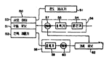
처음에 제3도를 참조하여 설명하면 본 발명에 의한 진동레오미터장치는 총괄적으로 참조부호(50)으로 표시되는 진동점도계를 포함하고 있다. 이 진동점도계는 상세한 하기의 설명과 같이 전자구동유닛(51)과 진폭검출기(52)와 서모미터(53)를 구비하고 있다. 전자구동유닛(51)은 영구자석(13)(제1도)과 같이 움직이는 전자코일(12)(제1도)을 구비하고, 이 전자코일(12)는 발진기(54)와 가변증폭기(55)를 포함하는 제어유닛(56)으로부터 무단계로 또한 연속적으로 변화하는 크기의 구동전류를 받는다. 이 제어유닛(56)은 전자구동 유닛(51)에 공급하는 구동전류의 크기를 계측하는 전류계(57)를 구비하고 있다. 또 한편 진폭검출기(52)는 예를들면 비접촉방식와 전류손 검출형 변위검출기(14)(제1도)로 구성되고,이 검출기(14)의 출력신호를 진폭표시유닛(58)에 보낸다. 이 진폭표시유닛(58)은 검출기(14)의 출력측에 접속된 증폭기(59)의 출력을 전압치로 하여 계측하는 전압계(60)를 포함한다. 서모미터(53)는 온도 프로브(probe)(21)(제1도)를 구비하고, 이 프로브(21)의 출력신호는 온도표시기(61)에 공급된다.First, referring to FIG. 3, the vibration rheometer device according to the present invention includes a vibration viscometer collectively indicated by the
전류계(57)에 의한 계측치와 전압계(60)에 의한 계측치는 각각 X-Y 레코우더와 같은 기록유닛(62)에 보내지고, 이 기록유닛(62)은 전자구동유닛(51)에 보내지는 연속적이고, 또한 무단계로 변화하는 크기의 구동전류에 대응하는 진폭검출기(52)로부터의 진폭치의 변화를 표시하는 검출전압을 프로트한다.The measured value by the
본 발명에 사용하는 진동점도계 자체는 상기와 같이 본 발명등에 의한 미국 특허번호 제4,602,505호 및 번호 제4,729,237호에 개시되고 있다. 제1도를 참조하면 이 진동점도계는 베이스(도시생략)로부터 뻗는 프레임축(1)에 단단히 고정된 경질의 재료로 구성되는 중공의 지지블록(2)을 구비하고, 이 지지블록(2)은 하방으로 뻗는 지지컬럼(3)을 구비하고 있다. 지지블록(2)의 하단부에는 음차상 바이브레이터를 구성하는 1쌍의 바이브레이터서브어셈블리(4)가 고정되고, 이들의 바이브레이터서브어셈블리 (4)는 지지블록(2)으로부터 하방으로 뻗고, 또 지지컬럼(3)의 서로 반대측의 위치를 점유하고 있다. 각 바이브레이터서브어셈블리(4)는 그 일단부가 고정쇠(7)를 개재하여 나사(6)에 의하여 지지블록(2)에 고정된 리프스프링(5)과 이 리프스프링(5)의 타단부에 단단히 장치되어 긴 중간플레이트(8)와 이 중간플레이트(8)의 단부에 있는 나사(10)에 의하여 고정된 센서플레이트(9)를 포함하고 있다. 리프 스프링(5)은 향탄성 스프링강으로 제조되는 것이 좋고, 또 중간플레이트(8)는 에를들면 알루미늄과 같은 비교적 강성이 있는 가벼운 재료로 제작되는 것이 좋다. 센서플레이트(9)는 예를들면 두께 0.2mm 정도의 얇은 편평한 내약품성이 있는 스테인레스강으로 제작되는 것이 좋고, 이 센서플레이트의 자유단은 예를들면 직경 20mm정도의 디스크상(11)으로 형성되어 있다.The vibratory viscometer itself used in the present invention is disclosed in US Patent Nos. 4,602,505 and 4,729,237 according to the present invention as described above. Referring to FIG. 1, this vibratory viscometer has a hollow support block 2 made of a hard material firmly fixed to a
각 바이블레이터서브어셈메블리(4)는 다른쪽의 바이브레이터서브어셈블리와 대칭적으로 배치되어 있으며, 각기 지지컬럼(3)에 부착된 한쌍의 전자코일(12)과 협동하는 영구자석(13)을 중간플레이트(8)상에 가지고 있다. 각 전자코일(12)과 영구자석(13)과의 조합은 각기 대응하는 바이브레이터서브어셈블리(4)를 진동시키는 구동유닛(51)로서 작용하며, 이 구동유닛(51)는 상기한 바와 같이 제어유닛(56)(제3도)에서 무단계로 또한 연속적으로 변화하는 크기의 구동전류가 공급되며, 그것에 의해 한쌍의 바이브레이터어셈블리(4)를 동일주파수하에서 서로 반대위상 즉 180도의 위상차를 가지고 무단계로 또한 연속적으로 변화하는 크기의 가진력으로 진동시킨다. 바람직한 예에 의하면 구동주파수는 30Hz이며, 구동전류는 0에서 1000mA가지 직선적으로 변화한다. 한쌍의 센서플레이트(9)는 동일한 가상수직면내에 분포하고 있으며, 이 결과 그들의 상이한 가상수직면에 분포할 경우에 생기는 지지블록(2)에 있어서의 비틀림 반작용을 피할 수 있다. 각 전자코일(12)과 영구자석(13)과의 상대적인 배치는 반전시켜도 되지만, 도면에 도시된 예와 같이 전자코일(12)을 지지컬럼(3)측에 설치하면, 그 코일(12)의 리드선(15)을 지지컬러(3)내를 지나 단자쇠(16)(윗쪽)로 안내할 수 있는 점에서 적합하다.Each vibrator subassembly 4 is arranged symmetrically with the other vibrator subassembly, and each of the permanent magnets 13 cooperates with a pair of electromagnetic coils 12 attached to the support column 3. On the intermediate plate (8). The combination of each of the electromagnetic coils 12 and the permanent magnets 13 acts as a drive unit 51 which vibrates the corresponding vibrator subassembly 4, respectively, which drive unit 51 has a control unit as described above. In (56) (FIG. 3), a drive current of stepless and continuously varying magnitude is supplied, whereby a pair of vibrator assemblies 4 are continuously stepwise and continuously stepwise with a phase difference of 180 degrees out of phase with each other under the same frequency. It vibrates with excitation force of varying size. According to a preferred example, the driving frequency is 30 Hz, and the driving current varies linearly from 0 to 1000 mA. The pair of sensor plates 9 are distributed in the same virtual vertical plane, and as a result, the torsional reaction in the support block 2 which occurs when they are distributed in their different virtual vertical planes can be avoided. The relative arrangement of each of the electromagnetic coils 12 and the permanent magnets 13 may be reversed. However, when the electromagnetic coils 12 are provided on the support column 3 side as in the example shown in the drawing, the coils 12 It is suitable in that the
지지블록(2)과 전자코일(12)과의 사이의 지지컬러(3)에는 바이브레이터서브어셈블리(4)의 리프스프링(5)과 대향하도록 변위검출기(14)가 설치되어 있으며, 이 변위검출기(14)는 한쪽의 바이브레이터서브어셈블리(4)의 진폭을 전기신호로 변환한다. 이 경우, 다른쪽 바이브레이터서브어셈블리를 위한 또 하나의 변위검출기가 설치되어 있어도 되지만 양 바이브레이터서브어셈블리(4)는 실질적으로 동일한 진폭을 나타내므로, 그 한쪽만으로 족하다. 변위검출기(14)는 나중에 설명하는 바와 같이 한쌍의 센서플레이트(9)가 샘플내에 삽입되면, 그 점성저항의 변화에 의해 바이브레이터서브어셈블리(14)의 진폭에 영향이 생기기 때문에, 이 진폭을 전기적으로 검출하는 것으로서, 그 검출치에서 샘플의 점도를 공지의 방법에 의해 연산한다. 변위검출기(14)는 예를들면 공지의 비접촉방식의 와전류손 검출형이라도, 좋지만, 이 공지의 변위검출기를 사용할 경우에는 이것과 대향하는 리프스프링(5)을 자성스프링 강철로 형성한다. 와전류손 검출형 변위센서 대신 공지의 광학식 변위센서를 사용할 수도 있다. 변위검출기(14)의 리드선(17)도 역시 지지컬럼(3)내를 지나 공통단자쇠(16)에 안내한다.A displacement detector 14 is provided on the support color 3 between the support block 2 and the electromagnetic coil 12 so as to face the leaf spring 5 of the vibrator subassembly 4. 14 converts the amplitude of one vibrator subassembly 4 into an electrical signal. In this case, another displacement detector for the other vibrator subassembly may be provided, but both vibrator subassemblies 4 exhibit substantially the same amplitude, so that only one of them is sufficient. As described later, the displacement detector 14 electrically converts the amplitude of the vibrator subassembly 14 when the pair of sensor plates 9 are inserted into the sample, because the change in the viscous resistance affects the amplitude of the vibrator subassembly 14. By detecting, the viscosity of a sample is computed by a well-known method at the detected value. The displacement detector 14 may be, for example, a known non-contact eddy current loss detection type. However, when the known displacement detector is used, the leaf spring 5 opposed to this is formed of magnetic spring steel. Instead of the eddy current loss detection type displacement sensor, a known optical displacement sensor may be used. The lead wire 17 of the displacement detector 14 also passes through the support column 3 to guide the common terminal 16.
제2도에서는 지지컬럼(3)의 하단에는 총괄적으로 참조번호(20)으로 표시된 온도계가 부착되어 있으며, 이 온도계(20)의 시스(sheath)가 든 프로브(probe)(21)가 아래쪽으로 뻗어 있다. 이 온도 프로브(21)은 한쌍의 센서플레이트(9)의 중간위치를 차지하며, 또한 그것과 동일한 가상의 수직면내에 분포하고 있으며, 또 그 하단은 한쌍의 센서플레이트(9)와 대략 동일한 가상수평면내에 분포하고 있다. 온도프로브(21)는 한쌍의 센서플레이트(9)와 동일한 가상수직면내에 정렬되어 있기 때문에, 이들 센서플레이트간에 온도 프로브(21)가 존재하는 것에 의한 샘플난류의 발생을 방지한다. 온도계(20)는 예를들면 시스내에 백금측은 저항체를 갖는 공지의 것이라도 좋으며, 이 공지의 온도계는 시스의 기단에 증폭기를 포함하는 회로유닛(22)을 갖는다. 회로유닛(22)의 리드선(23)은 지지컬럼(3)내를 지나 공통단자쇠(16)에 이른다.In FIG. 2, a thermometer, generally indicated by reference numeral 20, is attached to the lower end of the support column 3, and a probe 21 having a sheath of the thermometer 20 extends downward. have. The temperature probe 21 occupies an intermediate position of the pair of sensor plates 9 and is distributed in the same virtual vertical plane, and the lower end thereof is substantially in the same virtual horizontal plane as the pair of sensor plates 9. It is distributed. Since the temperature probes 21 are aligned in the same virtual vertical plane as the pair of sensor plates 9, the generation of sample turbulence due to the presence of the temperature probes 21 between these sensor plates is prevented. The thermometer 20 may be, for example, a known one having a resistor on the platinum side in the sheath, which has a circuit unit 22 including an amplifier at the base of the sheath. The
지지컬럼(3)의 하단부에는 외부나사(30)가 형성되며, 이 외부나사(30)나 나사맞춤하는 조정너트멤버(31)를 갖는 캐리어장치(32)가 지지컬럼(3)에 부착되어 있다. 캐리어장치(32)는 샘플용기(33)를 떼고 붙일 수 있게 지지하며, 또한 이 샘플용기(33)의 개방면을 폐쇄하는 뚜껑의 역할을 한다. 샘플용기(33)는 비이커와 같이 투명유리로 만들어져 있으면 편리하며, 이 용기는 개구 가장자리 둘레에 플랜지(34)를 가지며, 또 그안에 들어간 샐플(35)의 허용량을 나타내는 2개의 평행선으로 이루어진지표(36)가 붙여져 있다. 캐리어장치(32)는 샘플용기(33)안에 꼭 맞게 끼워 넣어지는 평면적인 크기를 가진 예를들어 단열성에 뛰어난 합성수지로 이루어진 뚜껑 멤버(37)를 포함하며, 이 뚜껑멤버(37)는 플랜지(38)를 가지고 있다. 뚜껑멤버(37)에는 공지인 한쌍의 체결쇠(clamp)(39)가 설치되며, 이들 체결쇠(39)를 샘플용기(33)의 플랜지(34)에 걸어맞추면 캐리어장치(32)에 샘플용기(33)를 부착할 수 있다. 지지컬러(3)의 외부나사(30)와 나사맞춤하는 조정너트멤버(31)는 아래쪽에 스토퍼(40)를 가지고 있으며, 그 스토퍼(40)에 의해 축방향의 이동이 제한된다. 뚜껑멤버(37)에는 지지컬럼(3)의 하단부가 통과할 수 있는 구멍(41)과, 한쌍의 센서플레이트(9)가 통과할 수 있는 한쌍의 열확산을 방지하는 가는 슬릿(42)이 형성되어 있다.An
통상, 캐리어장치(32)는 지지컬럼(3)의 하단부에 장착되어 있고, 이 캐리어장치(32)에 샘플용기(33)를 착탈자재로 부착한다. 지지컬럼(3)의 하단에는 2개의 핀(44)이 하향으로 고정되어 있으며, 이들 핀(44)은 온도프로브(21)의 서로 반대측에 있고, 그 프로브와 센서플레이트(9)와의 사이의 위치를 차지하며 또한 그 센서플레이트(9) 및 온도프로브(21)가 분포하는 가상수직면내에 정렬되어 있다. 핀(44)은 지지컬럼(3)에 대한 샘플용기(33)의 상대적인 높이 위치를 결정하기 위해, 그 선단이 용기(33)내의 샘플(35)의 바람직한 표면 레벨을 나타내는 인디케이터로서의 역할을 한다. 즉, 핀(44)의 선단과 샘플(35)의 표면 레벨과의 사이가 위치하지 않는다면, 캐리어장치(32)의 조정너트멤버(31)를 회전시켜, 이 캐리어장치(32)와 함께 샘플용기(33)를 지지컬럼(3)에 대해 축방향으로 움직이며, 이렇게 함으로써 상기와 같은 불일치를 해소한다. 이 결과, 샘플용기(33)내에 엄밀하게 결정된 양의 샘플을 넣는 번거러움 없이, 샘플용기(33)에 붙여진 2개의 지표라인(36)간의 허용범위내의 상이한 양의 샘플을 넣어도, 그 샘플내에 센서플레이트(9)와 온도프로브(21)를 항상 일정길이만큼 삽입가능하게 되며 이들의 삽입깊이의 차이에 의한 측정오차를 방지할 수 있다.Usually, the carrier apparatus 32 is attached to the lower end of the support column 3, and attaches the
제4도, 제5도 및 제6도는 본 발명의 바람직한 예에 따라 제작된 진동레오미터장치를 사용하여 3종류의 샘플의 유동특성을 측정한 결과를 나타내는 그래프이지만, 이들그래프에 있어서는 종축은 한쌍의 바이브레이터서브어셈블리(4)에 주어지는 가진력에 해당하는 구동전류의 크기 I을 나타내며, 횡축은 상기 가진력 응답하는 상기 한쌍의 바이브레이터서브어셈블리(4)의 진폭에 해당하는 검출전압의 크기 E를 나타내고 있다. 이 경우, 제4도는 마요네즈, 제5도는 콜드크림 및 제6도는 유액을 샘플로 하는 것이지만, 제4도와 제5도에 의하면 가진력을 점차 크게 해서 구한 곡선과, 이것을 반대로 점차 작게 해서 구한 곡선이 히스테리시스폐곡선을 그리며, 이들 샘플이 틱소트로피(thixotropy)적인 비뉴톤점성을 나타내는 것을 알 수 있고, 또 제6도에 의하면 가진력의 변화에 대한 진폭의 변화는 리니어도 되어, 이 샘플은 뉴톤점성을 나타내는 물자라는 것이 판명된다.4, 5, and 6 are graphs showing the results of measuring the flow characteristics of three types of samples using a vibratory rheometer device manufactured according to a preferred example of the present invention. Represents the magnitude I of the drive current corresponding to the excitation force given to the vibrator subassembly 4, and the horizontal axis represents the magnitude E of the detection voltage corresponding to the amplitude of the pair of vibrator subassemblies 4 responding to the excitation force. In this case, Fig. 4 shows mayonnaise, Fig. 5 uses cold cream and Fig. 6 shows fluid as a sample, but according to Figs. It is shown that these samples show thixotropy non-Newtonian viscosity, drawing a closed curve, and according to FIG. 6, the change in amplitude with respect to the change of excitation force can be linear, and this sample is a material showing Newtonian viscosity. It turns out.
제7도는 여러가지 측정패턴에 있어서의 구동전류의 모양을 설명하는 그래프이며, 이들 그래프에 있어서는 종축은 전류치 I횡축은 시간 T를 나타낸다. 각 그래프가 나타내는 측정패턴의 상황은 다음과 같다.7 is a graph for explaining the shape of the drive current in various measurement patterns, in which the vertical axis represents the current value I and the horizontal axis represents the time T. FIG. The situation of the measurement pattern which each graph represents is as follows.
제7a도 패턴 1 : 시간 t0에서 t1까지의 동안, 무단계로 또한 연속적으로 증대시키고, 이어서 t1에서 t2까지의 동안, 무단계로 또한 연속적으로 감소시킨다.Figure 7a also shows a pattern 1: steplessly and continuously increasing during time t0 to t1, and then steplessly and continuously during t1 to t2.
제7b도 패턴 2 : 상기 패턴 1과 같이 시간 t1까지는 연속적으로 증대시키고, 이 시간 t1이후는 일정하게 홀드한다.Fig. 7b Pattern 2: Like
제7c도 패턴 3 : 상기 패턴1과 같이 시간 t1까지는 연속적으로 증대시킨 다음, 다음의 시간 t2까지의 동안은 일정하게 홀드하고, 이어서 0에 커트 오프한다.Fig. 7C Pattern 3: Like the
제7d도 패턴 4 : 상기 패턴 1과 같이 시간 t1까지는 연속적으로 증대시키고, 다음의 시간 t2까지의 동안은 반대로 무단계로 또한 연속적으로 하강시켜, 이들 상승과 하강을 반복한다.Fig. 7d Pattern 4: Similarly to
위에 기술된 측정패턴은 어디까지나 실시예이며, 본 발명에 의하면 이들 측정패턴은 제한됨이 없이 더욱 여러가지의 변형이 가능하다.The measurement patterns described above are only examples, and according to the present invention, these measurement patterns are not limited, and more various modifications are possible.
Claims (6)
Applications Claiming Priority (3)
| Application Number | Priority Date | Filing Date | Title |
|---|---|---|---|
| JP62-289521 | 1987-11-18 | ||
| JP?62-289521 | 1987-11-18 | ||
| JP62289521A JPH01132931A (en) | 1987-11-18 | 1987-11-18 | Method for analyzing physical properties of sample by viscometer |
Publications (2)
| Publication Number | Publication Date |
|---|---|
| KR890008548A KR890008548A (en) | 1989-07-12 |
| KR920003532B1 true KR920003532B1 (en) | 1992-05-02 |
Family
ID=17744332
Family Applications (1)
| Application Number | Title | Priority Date | Filing Date |
|---|---|---|---|
| KR1019880015197A KR920003532B1 (en) | 1987-11-18 | 1988-11-18 | Vibration type rheometer apparatus |
Country Status (7)
| Country | Link |
|---|---|
| US (1) | US4941346A (en) |
| EP (1) | EP0317356B1 (en) |
| JP (1) | JPH01132931A (en) |
| KR (1) | KR920003532B1 (en) |
| CN (1) | CN1016279B (en) |
| CA (1) | CA1315126C (en) |
| DE (2) | DE3877913T2 (en) |
Families Citing this family (32)
| Publication number | Priority date | Publication date | Assignee | Title |
|---|---|---|---|---|
| FR2664981B1 (en) * | 1990-07-20 | 1994-04-29 | Serbio | DEVICE FOR DETECTING THE CHANGE IN VISCOSITY OF A LIQUID ELECTROLYTE BY THE EFFECT OF DEPOLARIZATION. |
| JPH04118543A (en) * | 1990-09-08 | 1992-04-20 | Chichibu Cement Co Ltd | Measurement device |
| US6494079B1 (en) * | 2001-03-07 | 2002-12-17 | Symyx Technologies, Inc. | Method and apparatus for characterizing materials by using a mechanical resonator |
| US6227039B1 (en) | 1998-01-06 | 2001-05-08 | Moshe Te'eni | System and method for controlling concrete production |
| CN1067896C (en) * | 1998-03-10 | 2001-07-04 | 王启明 | Externally used medicine for fishes |
| US6023961A (en) | 1998-04-02 | 2000-02-15 | Reliance Electric Industrial Company | Micro-viscosity sensor and lubrication analysis system employing the same |
| US6546785B1 (en) | 1998-04-02 | 2003-04-15 | Rockwell Automation Technologies, Inc. | System and method for dynamic lubrication adjustment for a lubrication analysis system |
| US6324899B1 (en) | 1998-04-02 | 2001-12-04 | Reliance Electric Technologies, Llc | Bearing-sensor integration for a lubrication analysis system |
| US6664067B1 (en) * | 2000-05-26 | 2003-12-16 | Symyx Technologies, Inc. | Instrument for high throughput measurement of material physical properties and method of using same |
| US6484567B1 (en) * | 2000-08-03 | 2002-11-26 | Symyx Technologies, Inc. | Rheometer for rapidly measuring small quantity samples |
| US6736017B2 (en) | 2001-08-24 | 2004-05-18 | Symyx Technologies, Inc. | High throughput mechanical rapid serial property testing of materials libraries |
| US6772642B2 (en) | 2001-08-24 | 2004-08-10 | Damian A. Hajduk | High throughput mechanical property and bulge testing of materials libraries |
| US6769292B2 (en) | 2001-08-24 | 2004-08-03 | Symyx Technologies, Inc | High throughput rheological testing of materials |
| US6690179B2 (en) | 2001-08-24 | 2004-02-10 | Symyx Technologies, Inc. | High throughput mechanical property testing of materials libraries using capacitance |
| US6650102B2 (en) | 2001-08-24 | 2003-11-18 | Symyx Technologies, Inc. | High throughput mechanical property testing of materials libraries using a piezoelectric |
| US7721590B2 (en) | 2003-03-21 | 2010-05-25 | MEAS France | Resonator sensor assembly |
| US7581434B1 (en) | 2003-09-25 | 2009-09-01 | Rockwell Automation Technologies, Inc. | Intelligent fluid sensor for machinery diagnostics, prognostics, and control |
| CN100381805C (en) * | 2006-01-11 | 2008-04-16 | 浙江大学 | Pressure adjustable and external drum rotary rheometer with visible concentric drums |
| CN101526459B (en) * | 2009-04-16 | 2012-11-14 | 中国船舶重工集团公司第七二五研究所 | Flectrorheological material damping performance test device and method thereof |
| FR2954498B1 (en) * | 2009-12-23 | 2012-03-16 | Snpe Materiaux Energetiques | DEVICE FOR CONTROLLING A VISCOELASTIC MATERIAL |
| DE102010049766B4 (en) * | 2010-10-29 | 2016-10-06 | Hochschule Merseburg (Fh) | Method and apparatus for measuring viscosity |
| WO2012115520A1 (en) * | 2011-02-25 | 2012-08-30 | Esquisse Schoonhoven | Method and device for determining of shearing stress or viscosity |
| CN103163066B (en) * | 2013-02-19 | 2015-09-30 | 中山大学 | A kind of liquid machine loss analysis instrument |
| CN104246473A (en) * | 2013-02-28 | 2014-12-24 | 株式会社爱安德 | Method for finding shear rate of fluid, and program and device for same |
| CN105051517A (en) * | 2013-04-03 | 2015-11-11 | 高准公司 | Vibratory sensor and method |
| JP6169092B2 (en) * | 2013-08-29 | 2017-07-26 | 株式会社エー・アンド・デイ | Method, program and apparatus for evaluating reach distance of shear rate acting on fluid |
| JP2015190829A (en) * | 2014-03-28 | 2015-11-02 | 株式会社エー・アンド・デイ | Method, program, and device for determining yield value of fluid |
| DE102014015301B3 (en) * | 2014-10-13 | 2016-02-25 | Technische Universität Bergakademie Freiberg | Method for determining the viscosity of fluids in the high temperature range by means of a vibration body viscometer and associated vibration body viscometer |
| WO2016143719A1 (en) * | 2015-03-06 | 2016-09-15 | 国立研究開発法人物質・材料研究機構 | Molecular weight measurement method and molecular weight measurement device |
| CN107787448B (en) * | 2015-04-17 | 2020-07-24 | 雷奥尼克斯有限公司 | Corrosion time profile measuring device |
| US10119896B2 (en) * | 2015-12-31 | 2018-11-06 | Xiang Yan | Electromechanical transducers for fluid viscosity measurement |
| CN110103739B (en) * | 2019-04-18 | 2021-03-26 | 南京航空航天大学 | Weak magnetic field excitation three-coil detection device |
Family Cites Families (7)
| Publication number | Priority date | Publication date | Assignee | Title |
|---|---|---|---|---|
| FR899057A (en) * | 1942-10-22 | 1945-05-18 | Ig Farbenindustrie Ag | Viscometer for carrying out measurements and adjustments |
| US3722262A (en) * | 1972-03-16 | 1973-03-27 | Massachusetts Inst Technology | Oscillating viscometer |
| SU612160A1 (en) * | 1977-01-19 | 1978-06-25 | Всесоюзный научно-исследовательский институт хлебопекарной промышленности | Vibration-type viscosimeter |
| US4166381A (en) * | 1978-02-24 | 1979-09-04 | E. I. Du Pont De Nemours And Company | Apparatus for determining the viscosity of fluids |
| JPS57135337A (en) * | 1981-02-16 | 1982-08-20 | Chichibu Cement Co Ltd | Measuring method for viscosity of fluid |
| JPS59107236A (en) * | 1982-12-13 | 1984-06-21 | Chichibu Cement Co Ltd | Viscosity measuring method |
| JPS62137537A (en) * | 1985-12-12 | 1987-06-20 | Chichibu Cement Co Ltd | Sample temperature measuring apparatus for viscosity measuring device |
-
1987
- 1987-11-18 JP JP62289521A patent/JPH01132931A/en active Granted
-
1988
- 1988-11-17 CA CA000583386A patent/CA1315126C/en not_active Expired - Fee Related
- 1988-11-18 DE DE8888310943T patent/DE3877913T2/en not_active Expired - Fee Related
- 1988-11-18 US US07/273,273 patent/US4941346A/en not_active Expired - Lifetime
- 1988-11-18 CN CN88109207A patent/CN1016279B/en not_active Expired
- 1988-11-18 EP EP88310943A patent/EP0317356B1/en not_active Expired - Lifetime
- 1988-11-18 KR KR1019880015197A patent/KR920003532B1/en not_active IP Right Cessation
- 1988-11-18 DE DE198888310943T patent/DE317356T1/en active Pending
Also Published As
| Publication number | Publication date |
|---|---|
| JPH01132931A (en) | 1989-05-25 |
| DE3877913T2 (en) | 1993-05-19 |
| DE3877913D1 (en) | 1993-03-11 |
| KR890008548A (en) | 1989-07-12 |
| EP0317356A3 (en) | 1990-03-28 |
| JPH0470579B2 (en) | 1992-11-11 |
| EP0317356B1 (en) | 1993-01-27 |
| CA1315126C (en) | 1993-03-30 |
| CN1016279B (en) | 1992-04-15 |
| US4941346A (en) | 1990-07-17 |
| CN1036454A (en) | 1989-10-18 |
| DE317356T1 (en) | 1990-04-12 |
| EP0317356A2 (en) | 1989-05-24 |
Similar Documents
| Publication | Publication Date | Title |
|---|---|---|
| KR920003532B1 (en) | Vibration type rheometer apparatus | |
| US4679427A (en) | Apparatus for measuring viscosity | |
| CA1282252C (en) | Tuning fork vibration-type viscosity measuring apparatus | |
| US4602501A (en) | Rheometer | |
| US3382706A (en) | Oscillatory element for measuring viscosity | |
| US4341111A (en) | Process and apparatus for determining the visco elastic characteristics of fluids | |
| US6484567B1 (en) | Rheometer for rapidly measuring small quantity samples | |
| US5449493A (en) | Stirring device | |
| EP0611448B1 (en) | A device for determining viscoelastic properties of liquids and method for use | |
| US4799378A (en) | Piezoelectric viscometer | |
| RU2307361C2 (en) | Electrostatic voltmeter | |
| JPS63167238A (en) | Adjusting device for insertion depth of sensing plate for viscosity measuring instrument | |
| Murayama | Measurement of dynamic viscoelastic properties of polymer melts and liquids by the modified rheovibron | |
| JPH10267823A (en) | Vibration-type viscosimeter | |
| JPH0540869U (en) | Rigid body pendulum for viscoelasticity measurement | |
| JPH04357439A (en) | Apparatus for measuring electrorheological properties | |
| UA44152A (en) | METHOD OF DETERMINATION OF VISCOSITY |
Legal Events
| Date | Code | Title | Description |
|---|---|---|---|
| A201 | Request for examination | ||
| G160 | Decision to publish patent application | ||
| E701 | Decision to grant or registration of patent right | ||
| GRNT | Written decision to grant | ||
| FPAY | Annual fee payment |
Payment date: 20000426 Year of fee payment: 9 |
|
| LAPS | Lapse due to unpaid annual fee |